EP0035943A1 - Magnetkopf mit veränderbarer Spurbreite zum magnetischen Aufzeichnen oder Wiedergeben von Daten - Google Patents
Magnetkopf mit veränderbarer Spurbreite zum magnetischen Aufzeichnen oder Wiedergeben von Daten Download PDFInfo
- Publication number
- EP0035943A1 EP0035943A1 EP81400351A EP81400351A EP0035943A1 EP 0035943 A1 EP0035943 A1 EP 0035943A1 EP 81400351 A EP81400351 A EP 81400351A EP 81400351 A EP81400351 A EP 81400351A EP 0035943 A1 EP0035943 A1 EP 0035943A1
- Authority
- EP
- European Patent Office
- Prior art keywords
- magnetic
- width
- magnetic head
- air gap
- reading
- Prior art date
- Legal status (The legal status is an assumption and is not a legal conclusion. Google has not performed a legal analysis and makes no representation as to the accuracy of the status listed.)
- Granted
Links
- 230000005291 magnetic effect Effects 0.000 title claims abstract description 82
- 238000004804 winding Methods 0.000 claims description 10
- 239000000696 magnetic material Substances 0.000 claims description 6
- 238000004519 manufacturing process Methods 0.000 claims description 5
- 238000000605 extraction Methods 0.000 claims description 4
- 238000000034 method Methods 0.000 claims description 4
- 239000000463 material Substances 0.000 claims description 3
- 230000005355 Hall effect Effects 0.000 claims description 2
- 239000003302 ferromagnetic material Substances 0.000 claims 1
- 239000000523 sample Substances 0.000 claims 1
- 238000005245 sintering Methods 0.000 claims 1
- 238000006073 displacement reaction Methods 0.000 abstract 1
- 229910000859 α-Fe Inorganic materials 0.000 description 6
- 230000008901 benefit Effects 0.000 description 3
- 230000006698 induction Effects 0.000 description 3
- 238000005520 cutting process Methods 0.000 description 2
- 238000010586 diagram Methods 0.000 description 2
- 230000008569 process Effects 0.000 description 2
- 238000000926 separation method Methods 0.000 description 2
- 229910001369 Brass Inorganic materials 0.000 description 1
- 229910001308 Zinc ferrite Inorganic materials 0.000 description 1
- 230000033228 biological regulation Effects 0.000 description 1
- 239000010951 brass Substances 0.000 description 1
- 230000008859 change Effects 0.000 description 1
- 230000004907 flux Effects 0.000 description 1
- 230000006872 improvement Effects 0.000 description 1
- 230000005389 magnetism Effects 0.000 description 1
- 230000005415 magnetization Effects 0.000 description 1
- 238000005457 optimization Methods 0.000 description 1
- 230000010287 polarization Effects 0.000 description 1
- 230000002441 reversible effect Effects 0.000 description 1
- 230000035945 sensitivity Effects 0.000 description 1
- 230000009897 systematic effect Effects 0.000 description 1
- WGEATSXPYVGFCC-UHFFFAOYSA-N zinc ferrite Chemical compound O=[Zn].O=[Fe]O[Fe]=O WGEATSXPYVGFCC-UHFFFAOYSA-N 0.000 description 1
Images



Classifications
-
- G—PHYSICS
- G11—INFORMATION STORAGE
- G11B—INFORMATION STORAGE BASED ON RELATIVE MOVEMENT BETWEEN RECORD CARRIER AND TRANSDUCER
- G11B5/00—Recording by magnetisation or demagnetisation of a record carrier; Reproducing by magnetic means; Record carriers therefor
- G11B5/127—Structure or manufacture of heads, e.g. inductive
- G11B5/187—Structure or manufacture of the surface of the head in physical contact with, or immediately adjacent to the recording medium; Pole pieces; Gap features
- G11B5/245—Structure or manufacture of the surface of the head in physical contact with, or immediately adjacent to the recording medium; Pole pieces; Gap features comprising means for controlling the reluctance of the magnetic circuit in a head with single gap, for co-operation with one track
- G11B5/2452—Structure or manufacture of the surface of the head in physical contact with, or immediately adjacent to the recording medium; Pole pieces; Gap features comprising means for controlling the reluctance of the magnetic circuit in a head with single gap, for co-operation with one track where the dimensions of the effective gap are controlled
Definitions
- the present invention relates to the field of magnetic recording, and relates to electromagnetic transducers usually referred to as "heads". Such transducers cooperate with a mobile magnetizable support whose local variations in the magnetic state represent the actual recording, and have the function of converting these variations into an exploitable electrical signal available at their terminals. Symmetrically, the application of an electrical signal to their terminals determines a variable magnetization in the mobile magnetizable support which is scrolled in front of these transducers.
- the width of the air gap and the material of which the magnetic circuit is made are not the same if we want to optimize the result of each operation. This is the case, for example, in the field of electroacoustics.
- the recording air gap is simply chosen to have, transversely, a length three times the length of the reading air gap.
- the recording and reading head for magnetic data which is the subject of the present invention does not have this drawback.
- the invention calls upon the physical fact that, in the field of magnetic recording, the processes of recording and reading are not reversible.
- the recording and reading head of the invention exploits this difference.
- the invention relates to a magnetic head for recording and reading magnetic data, with variable track width, on a mobile support, comprising on the one hand a magnetic circuit in the shape of a torus, and on the other hand electrical means ensuring the respective application and extraction of recording and reading signals, the circuit being provided with an air gap cooperating with the movable support, and delimited by two polar faces, of rectangular outline, arranged opposite -screw, characterized in that, transversely to the plane of the torus, the respective dimensions of the two pole faces are different, the largest determining, on the mobile support, the width recorded, and the smallest determining the width read.
- FIG. 1 represents a recording-reading head with two air gaps according to the known art.
- the magnetic circuit 1 consists of a magnetic circuit 1 in the form of a torus and two recording 2 and reading 3 windings, crossed by the magnetic circuit.
- This is provided with two air gaps 4 and 5, respectively for recording and reading, both of which are filled with shims 6, 7 made of a non-magnetic material such as brass.
- the reading air gap 5 is transversely of width (L 1 ) less than that (L 2 ) of the recording air gap 4, in order to obtain that, for the reasons explained above, during the successive passages of the magnetizable support 8 in front in the air gaps, the width of the track actually read is less than the width of the recorded track.
- a magnetic head of this type has the disadvantage of not ensuring the separation of the functions of the air gaps, and it can be seen, at the respective stages of recording and reading, that the two air gaps record and read simultaneously, with creation of spurious offset signals. in time.
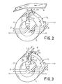
- FIG. 2 represents a record-read head with a single air gap according to the invention.
- the head is characterized in that the respective transverse dimensions L and L 2 of the two pole surfaces opposite the single air gap are different.
- the magnetic state of the magnetizable support is defined, as has also been explained above, by the field existing at the outlet edge 11 of the air gap, corresponding to the width L 2 which is the large transverse dimension of the air gap.
- the magnetic efficiency of the lateral parts of the outlet edge is obtained, for the most part, thanks to the leakage force lines such as 12 and 13, which close laterally in the air the force lines of the induction prevailing in the magnetic circuit.
- FIG. 3 represents an alternative embodiment of the recording-reading head of FIG. 2, comprising a lateral air gap field distributor.
- the magnetic reluctance presented to the lines of leakage force 12, 13 in the air of the head of FIG. 2 is reduced, by arranging, on each side of the pole surface corresponding to the small transverse width L l , two plates 21 and 22 made of magnetic material, constituting a lateral field distributor in the air gap.
- This distributor further increases the useful induction which prevails in the entire magnetic circuit of the head, and its role thus extends until the improvement of the output level of the electrical signal collected at the terminals of the windings in reading.
- FIG. 4 represents a diagram, in rectangular axes, summarizing the experimental studies made by the Applicant, on the one hand on the thickness of the side plates, on the other hand on the sensitivity to transverse shifts due to the running instabilities.
- Figures 5 to 13 show the different stages of a manufacturing process according to the invention.
- FIG. 5 two perfectly rectified and polished ferrite plates 30, 31 have been shown, plates between which a thin layer of non-magnetic ferrite 32 is interposed (FIG. 6a).
- a zinc ferrite paste 33 is deposited on the magnetic ferrite plate 31.
- the thickness of the ferrite film or of ferrite paste is between 10 and 100 microns and preferably 10 and 60 microns.
- This non-magnetic layer is then sintered under pressure to obtain a block shown in FIG. 7, having a homogeneous structure.
- the non-magnetic area shown par 34 is therefore located in the median plane of this homogeneous block.
- a cutting operation then allows (see Figure 8) the production of bars such as 35, 36, 37, ... 38.
- Each substantially rectangular block such as 37 (shown in Figure 9 in close-up) is then subjected to a grooving operation of a semi-cylindrical groove 39 (see FIG. 10), said groove being substantially symmetrical with respect to the plane containing the non-magnetic ferrite film 34.
- the following operation consists in making a cylindrical surfacing of the parallelepiped bar (FIG.
- the following operation consists in cutting the bar of FIG. 11 into individual heads of width L (see FIG. 12) and then in removing material by any suitable means so as to leave only a narrower part on the magnetic head. for the reading part, this part of the head having a width 1.
- These shoulders 43 and 44 have a thickness d, while the thickness of the air gap 45 has a value e.
- the two shoulders 43 and 44 will have the same dimensions, which gives symmetry to the read head, a structure which is preferable in order to fully benefit from the advantages of the invention.
- FIG. 13 a read and / or write head according to the invention is shown diagrammatically as produced according to the method described above.
- the upper part of this head conforms to the part shown in FIG. 1, while a magnetic closing circuit 46 in the form of a U has been added, as well as writing and reading windings 47 and 48 respectively.
- FIG. 14 shows a very enlarged view of the magnetic strip and a projection of the head according to the invention. Recording takes place over the entire width L of the tape magnetic while reading is carried out over the width 1, less than L.
- the current circulating in the coil generates a magnetic field which is channeled to the magnetic strip by the writing arm 41.
- the lines of force penetrate into the magnetic layer of the strip and find on the other side of the air gap a section large enough to close in the frame 42 to the right of the air gap. This allows writing on the total width of the active face L.
- the magnetic strip which is the seat of an induction which therefore generates a field moves through the reading coil and gives rise to an electromotive force at the terminals thereof.
- the sudden change in section of the active face which goes from L to 1, means that the magnetic reluctance of the circuit is large at the edges and relatively low at the center, i.e. in the axis of the reading frame. .
- the width actually read on the magnetic strip has a value slightly greater than 1 but much smaller than L. This therefore effectively makes it possible to overcome the different mechanical tolerances involved in the operation of the systems for reading media. coated with magnetic tracks such as for example credit cards.
Landscapes
- Engineering & Computer Science (AREA)
- Manufacturing & Machinery (AREA)
- Magnetic Heads (AREA)
Applications Claiming Priority (2)
| Application Number | Priority Date | Filing Date | Title |
|---|---|---|---|
| FR8005418A FR2478357A1 (fr) | 1980-03-11 | 1980-03-11 | Tete magnetique d'enregistrement et de lecture de donnees magnetiques, a largeur de piste variable |
| FR8005418 | 1980-03-11 |
Publications (2)
| Publication Number | Publication Date |
|---|---|
| EP0035943A1 true EP0035943A1 (de) | 1981-09-16 |
| EP0035943B1 EP0035943B1 (de) | 1984-07-11 |
Family
ID=9239539
Family Applications (1)
| Application Number | Title | Priority Date | Filing Date |
|---|---|---|---|
| EP81400351A Expired EP0035943B1 (de) | 1980-03-11 | 1981-03-06 | Magnetkopf mit veränderbarer Spurbreite zum magnetischen Aufzeichnen oder Wiedergeben von Daten |
Country Status (6)
| Country | Link |
|---|---|
| US (1) | US4405959A (de) |
| EP (1) | EP0035943B1 (de) |
| JP (1) | JPS56134310A (de) |
| DE (1) | DE3164649D1 (de) |
| ES (2) | ES8202446A1 (de) |
| FR (1) | FR2478357A1 (de) |
Cited By (3)
| Publication number | Priority date | Publication date | Assignee | Title |
|---|---|---|---|---|
| EP0128625A1 (de) * | 1983-06-13 | 1984-12-19 | Koninklijke Philips Electronics N.V. | Magnetwandlerkopf zum Aufzeichnen von Information auf hohe Koerzitivkraft-Speichermedia |
| US4531170A (en) * | 1981-05-18 | 1985-07-23 | Tokyo Shibaura Denki Kabushiki Kaisha | Combination magnetic head |
| EP0174714A1 (de) * | 1984-08-29 | 1986-03-19 | Irwin Magnetic Systems, Inc. | Aufbau eines magnetischen Wandlerkopfes und Verfahren zu dessen Anwendung |
Families Citing this family (12)
| Publication number | Priority date | Publication date | Assignee | Title |
|---|---|---|---|---|
| DE3376903D1 (en) * | 1982-10-01 | 1988-07-07 | Mitsubishi Electric Corp | Disc drive for flexible discs with different track widths |
| US4819107A (en) * | 1984-08-29 | 1989-04-04 | Irwin Magnetic Systems, Inc. | Magnetic transducer head structure |
| JPH0831204B2 (ja) * | 1985-10-18 | 1996-03-27 | 富士通株式会社 | 薄膜磁気ヘツド |
| US4821126A (en) * | 1985-10-22 | 1989-04-11 | Fuji Photo Film Co., Ltd. | Magnetic recording method involving core pieces of different thickness |
| US4849841A (en) * | 1987-04-10 | 1989-07-18 | Irwin Magnetic Systems, Inc. | Transducer head core structure with recessed magnetic closures |
| US4883950A (en) * | 1987-05-23 | 1989-11-28 | The Furukawa Electric Co., Ltd. | Composite magnetic and optical head |
| KR0126289B1 (ko) * | 1988-02-09 | 1997-12-26 | 이우에 사또시 | 자기 헤드 및 그 제조 방법 |
| JP2600841B2 (ja) * | 1988-09-02 | 1997-04-16 | 三菱電機株式会社 | 磁気ヘッド |
| US5706145A (en) * | 1994-08-25 | 1998-01-06 | Hindman; Carl L. | Apparatus and methods for audio tape indexing with data signals recorded in the guard band |
| US5734533A (en) * | 1996-05-15 | 1998-03-31 | Read-Rite Corporation | Dual gap magnetic head and method of making the same |
| JPH10247305A (ja) * | 1997-03-03 | 1998-09-14 | Sanyo Electric Co Ltd | 複合型薄膜磁気ヘッドの製造方法 |
| GB0420443D0 (en) * | 2004-09-14 | 2004-10-20 | Ncr Int Inc | A card reader |
Citations (8)
| Publication number | Priority date | Publication date | Assignee | Title |
|---|---|---|---|---|
| FR1159760A (fr) * | 1955-09-06 | 1958-07-02 | Ibm | Transducteur à tête d'enregistrement large et tête de lecture étroite |
| US2947592A (en) * | 1955-08-25 | 1960-08-02 | Sperry Rand Corp | High frequency magnetic transducers |
| US3060279A (en) * | 1957-11-06 | 1962-10-23 | Emi Ltd | Magnetic transducing heads |
| CH395575A (de) * | 1961-10-17 | 1965-07-15 | Telefunken Patent | Zweispurlöschkopf |
| US3209078A (en) * | 1960-12-20 | 1965-09-28 | Siemens Ag | Magnetic head equipped with a hall generator |
| US3353168A (en) * | 1964-04-09 | 1967-11-14 | Potter Instrument Co Inc | Wide-record narrow-read magnetic head |
| GB1500593A (en) * | 1976-10-19 | 1978-02-08 | Data Recording Instr Co | Magnetic transducing heads |
| JPS5842579A (ja) * | 1981-09-09 | 1983-03-12 | 株式会社日立製作所 | 速度帰還形油圧エレベ−タ装置 |
Family Cites Families (6)
| Publication number | Priority date | Publication date | Assignee | Title |
|---|---|---|---|---|
| NL7210322A (de) * | 1972-07-26 | 1974-01-29 | ||
| JPS5838843B2 (ja) * | 1973-11-20 | 1983-08-25 | ティーディーケイ株式会社 | 磁気記録再生方式 |
| US4085430A (en) * | 1974-01-24 | 1978-04-18 | U.S. Philips Corporation | Thin film magnetic head with a gap formed between a loop shaped core part and a bridging core part |
| JPS51147312A (en) * | 1975-06-13 | 1976-12-17 | Canon Inc | Magnetic head |
| JPS5235616A (en) * | 1975-09-16 | 1977-03-18 | Alps Nootoronikusu Kk | Magnetic head |
| JPS545417A (en) * | 1977-06-14 | 1979-01-16 | Tdk Corp | Magnetic head |
-
1980
- 1980-03-11 FR FR8005418A patent/FR2478357A1/fr active Granted
-
1981
- 1981-03-06 DE DE8181400351T patent/DE3164649D1/de not_active Expired
- 1981-03-06 EP EP81400351A patent/EP0035943B1/de not_active Expired
- 1981-03-09 US US06/242,157 patent/US4405959A/en not_active Expired - Lifetime
- 1981-03-10 ES ES500235A patent/ES8202446A1/es not_active Expired
- 1981-03-11 JP JP3513381A patent/JPS56134310A/ja active Pending
- 1981-05-19 ES ES502314A patent/ES8206074A1/es not_active Expired
Patent Citations (9)
| Publication number | Priority date | Publication date | Assignee | Title |
|---|---|---|---|---|
| US2947592A (en) * | 1955-08-25 | 1960-08-02 | Sperry Rand Corp | High frequency magnetic transducers |
| FR1159760A (fr) * | 1955-09-06 | 1958-07-02 | Ibm | Transducteur à tête d'enregistrement large et tête de lecture étroite |
| GB831492A (en) * | 1955-09-06 | 1960-03-30 | Ibm | Improvements in magnetic transducers |
| US3060279A (en) * | 1957-11-06 | 1962-10-23 | Emi Ltd | Magnetic transducing heads |
| US3209078A (en) * | 1960-12-20 | 1965-09-28 | Siemens Ag | Magnetic head equipped with a hall generator |
| CH395575A (de) * | 1961-10-17 | 1965-07-15 | Telefunken Patent | Zweispurlöschkopf |
| US3353168A (en) * | 1964-04-09 | 1967-11-14 | Potter Instrument Co Inc | Wide-record narrow-read magnetic head |
| GB1500593A (en) * | 1976-10-19 | 1978-02-08 | Data Recording Instr Co | Magnetic transducing heads |
| JPS5842579A (ja) * | 1981-09-09 | 1983-03-12 | 株式会社日立製作所 | 速度帰還形油圧エレベ−タ装置 |
Non-Patent Citations (4)
| Title |
|---|
| Electronics, Vol. 46, No. 3, 1er Fevrier 1973 New York, US M. MURAI: "Hall-Effect Magnetic Sensor Reads Data at any Speed" pages 91-96 * figure 11 * * |
| IBM Technical Disclosure Bulletin, Vol. 18, No. 6, Novembre 1975 New York, US N. NETER et al.: "Magnetic Head" pages 1744-1745 * |
| PATENTS ABSTRACTS OF JAPAN, Vol. 1, No. 103, 13 Septembre 1977, page 3236 E77 & JP-A-52 035 616 (Momii) (18-03-1977) * en entier * * |
| PATENTS ABSTRACTS OF JAPAN, Vol. 3 No. 81, 12 Juillet 1979, page 76 E 122 & JP-A-54 058425 (Nippon Denki) (11-05-1979) * Abrege * * |
Cited By (3)
| Publication number | Priority date | Publication date | Assignee | Title |
|---|---|---|---|---|
| US4531170A (en) * | 1981-05-18 | 1985-07-23 | Tokyo Shibaura Denki Kabushiki Kaisha | Combination magnetic head |
| EP0128625A1 (de) * | 1983-06-13 | 1984-12-19 | Koninklijke Philips Electronics N.V. | Magnetwandlerkopf zum Aufzeichnen von Information auf hohe Koerzitivkraft-Speichermedia |
| EP0174714A1 (de) * | 1984-08-29 | 1986-03-19 | Irwin Magnetic Systems, Inc. | Aufbau eines magnetischen Wandlerkopfes und Verfahren zu dessen Anwendung |
Also Published As
| Publication number | Publication date |
|---|---|
| FR2478357A1 (fr) | 1981-09-18 |
| DE3164649D1 (en) | 1984-08-16 |
| ES500235A0 (es) | 1982-01-16 |
| ES8202446A1 (es) | 1982-01-16 |
| US4405959A (en) | 1983-09-20 |
| FR2478357B1 (de) | 1984-04-06 |
| JPS56134310A (en) | 1981-10-21 |
| ES502314A0 (es) | 1982-07-16 |
| ES8206074A1 (es) | 1982-07-16 |
| EP0035943B1 (de) | 1984-07-11 |
Similar Documents
| Publication | Publication Date | Title |
|---|---|---|
| EP0035943B1 (de) | Magnetkopf mit veränderbarer Spurbreite zum magnetischen Aufzeichnen oder Wiedergeben von Daten | |
| EP0188944A1 (de) | System für senkrechte Aufzeichnung und Verfahren zur Herstellung eines Magnetkopfes | |
| EP0046697B1 (de) | Integrierter Magnetwandler | |
| EP0452193B1 (de) | Herstellungsverfahren von einem magnetischen Wiedergabe-Aufzeichnungskopf | |
| EP0040994B1 (de) | Magnetwandler, der einen Spalt mit veränderbarer Grössen-Dimension aufweist, zur Wiedergabe oder zum Aufzeichnen von Informationen eines magnetischen Trägers | |
| EP0951010A1 (de) | Verfahren zur Herstellung einer Anordnung mit mehreren Magnetköpfen und so hergestellte Anordnung mit mehreren Köpfen | |
| EP0188943B1 (de) | Schreib-Magnetwandler zur transversalen Aufzeichnung | |
| EP0800160A1 (de) | Herstellungsverfahren für einen Doppel-Magnetkopf mit entgegengesetzten Azimuth-Spalten | |
| EP0132186B1 (de) | Höchstintegrierter Magnetwandler zum Schreiben von Informationen auf einem magnetischen Träger | |
| FR2471020A1 (fr) | Procede de fabrication d'un transducteur magnetique compose | |
| EP1810283A2 (de) | Aufzeichnungs- und/oder abspielgerät mit mehreren magnetköpfen mit azimut-spalten | |
| FR2802011A1 (fr) | Tete de lecture planaire a element magneto-resistif | |
| FR2622336A1 (fr) | Tete magnetique de lecture et d'enregistrement | |
| FR2877485A1 (fr) | Dispositif d'enregistrement et/ou de lecture a tetes magnetiques multiples azimutees | |
| JP4492418B2 (ja) | 薄膜磁気ヘッド及びその製造方法 | |
| EP0550322A1 (de) | Verfahren zur Herstellung eines Magnetkopfes für Schichten mit hohen koercitiven Feldern | |
| JP2948182B2 (ja) | 録再分離複合型磁気ヘッド | |
| JP3171183B2 (ja) | 録再分離複合型磁気ヘッド | |
| JPH11328632A (ja) | 磁気ヘッド | |
| FR2834375A1 (fr) | Tete magnetique integree pour l'enregistrement magnetique et procede de fabrication de cette tete magnetique | |
| FR2633428A1 (fr) | Tete magnetique d'enregistrement/lecture a plot supraconducteur | |
| EP0406229A1 (de) | Magnetkopf für hoch-koerzitivfeld-magnetspuren und herstellungsverfahren | |
| WO2001052245A1 (fr) | Tete magnetique d'ecriture multipistes a haute densite | |
| FR2688513A1 (fr) | Procede de realisation d'une tete magnetique de type perpendiculaire et tete obtenue par ce procede. | |
| JPH08111009A (ja) | Mrヘッドの製造方法 |
Legal Events
| Date | Code | Title | Description |
|---|---|---|---|
| PUAI | Public reference made under article 153(3) epc to a published international application that has entered the european phase |
Free format text: ORIGINAL CODE: 0009012 |
|
| AK | Designated contracting states |
Designated state(s): DE FR GB IT SE |
|
| 17P | Request for examination filed |
Effective date: 19811019 |
|
| RAP1 | Party data changed (applicant data changed or rights of an application transferred) |
Owner name: L.C.C.-C.I.C.E. - COMPAGNIE EUROPEENNE DE COMPOSAN |
|
| ITF | It: translation for a ep patent filed | ||
| GRAA | (expected) grant |
Free format text: ORIGINAL CODE: 0009210 |
|
| AK | Designated contracting states |
Designated state(s): DE FR GB IT SE |
|
| REF | Corresponds to: |
Ref document number: 3164649 Country of ref document: DE Date of ref document: 19840816 |
|
| RAP2 | Party data changed (patent owner data changed or rights of a patent transferred) |
Owner name: L.C.C.-C.I.C.E. - COMPAGNIE EUROPEENNE DE COMPOSAN |
|
| PLBE | No opposition filed within time limit |
Free format text: ORIGINAL CODE: 0009261 |
|
| STAA | Information on the status of an ep patent application or granted ep patent |
Free format text: STATUS: NO OPPOSITION FILED WITHIN TIME LIMIT |
|
| 26N | No opposition filed | ||
| ITTA | It: last paid annual fee | ||
| EAL | Se: european patent in force in sweden |
Ref document number: 81400351.3 |
|
| PGFP | Annual fee paid to national office [announced via postgrant information from national office to epo] |
Ref country code: SE Payment date: 19950217 Year of fee payment: 15 |
|
| PGFP | Annual fee paid to national office [announced via postgrant information from national office to epo] |
Ref country code: GB Payment date: 19950220 Year of fee payment: 15 Ref country code: DE Payment date: 19950220 Year of fee payment: 15 |
|
| PGFP | Annual fee paid to national office [announced via postgrant information from national office to epo] |
Ref country code: FR Payment date: 19950324 Year of fee payment: 15 |
|
| PG25 | Lapsed in a contracting state [announced via postgrant information from national office to epo] |
Ref country code: GB Effective date: 19960306 |
|
| PG25 | Lapsed in a contracting state [announced via postgrant information from national office to epo] |
Ref country code: SE Effective date: 19960307 |
|
| GBPC | Gb: european patent ceased through non-payment of renewal fee |
Effective date: 19960306 |
|
| PG25 | Lapsed in a contracting state [announced via postgrant information from national office to epo] |
Ref country code: FR Effective date: 19961129 |
|
| EUG | Se: european patent has lapsed |
Ref document number: 81400351.3 |
|
| PG25 | Lapsed in a contracting state [announced via postgrant information from national office to epo] |
Ref country code: DE Effective date: 19970101 |
|
| REG | Reference to a national code |
Ref country code: FR Ref legal event code: ST |