EP0036041A2 - Echangeur de chaleur pour toits, façades, clôtures et similaires - Google Patents
Echangeur de chaleur pour toits, façades, clôtures et similaires Download PDFInfo
- Publication number
- EP0036041A2 EP0036041A2 EP80107655A EP80107655A EP0036041A2 EP 0036041 A2 EP0036041 A2 EP 0036041A2 EP 80107655 A EP80107655 A EP 80107655A EP 80107655 A EP80107655 A EP 80107655A EP 0036041 A2 EP0036041 A2 EP 0036041A2
- Authority
- EP
- European Patent Office
- Prior art keywords
- heat exchanger
- extruded profile
- exchanger according
- tube
- profile
- Prior art date
- Legal status (The legal status is an assumption and is not a legal conclusion. Google has not performed a legal analysis and makes no representation as to the accuracy of the status listed.)
- Granted
Links
Images
Classifications
-
- F—MECHANICAL ENGINEERING; LIGHTING; HEATING; WEAPONS; BLASTING
- F24—HEATING; RANGES; VENTILATING
- F24S—SOLAR HEAT COLLECTORS; SOLAR HEAT SYSTEMS
- F24S80/00—Details, accessories or component parts of solar heat collectors not provided for in groups F24S10/00-F24S70/00
- F24S80/30—Arrangements for connecting the fluid circuits of solar collectors with each other or with other components, e.g. pipe connections; Fluid distributing means, e.g. headers
-
- F—MECHANICAL ENGINEERING; LIGHTING; HEATING; WEAPONS; BLASTING
- F24—HEATING; RANGES; VENTILATING
- F24S—SOLAR HEAT COLLECTORS; SOLAR HEAT SYSTEMS
- F24S20/00—Solar heat collectors specially adapted for particular uses or environments
- F24S20/60—Solar heat collectors integrated in fixed constructions, e.g. in buildings
- F24S20/66—Solar heat collectors integrated in fixed constructions, e.g. in buildings in the form of facade constructions, e.g. wall constructions
-
- F—MECHANICAL ENGINEERING; LIGHTING; HEATING; WEAPONS; BLASTING
- F24—HEATING; RANGES; VENTILATING
- F24S—SOLAR HEAT COLLECTORS; SOLAR HEAT SYSTEMS
- F24S10/00—Solar heat collectors using working fluids
- F24S10/70—Solar heat collectors using working fluids the working fluids being conveyed through tubular absorbing conduits
- F24S10/75—Solar heat collectors using working fluids the working fluids being conveyed through tubular absorbing conduits with enlarged surfaces, e.g. with protrusions or corrugations
-
- F—MECHANICAL ENGINEERING; LIGHTING; HEATING; WEAPONS; BLASTING
- F24—HEATING; RANGES; VENTILATING
- F24S—SOLAR HEAT COLLECTORS; SOLAR HEAT SYSTEMS
- F24S20/00—Solar heat collectors specially adapted for particular uses or environments
- F24S20/60—Solar heat collectors integrated in fixed constructions, e.g. in buildings
- F24S20/67—Solar heat collectors integrated in fixed constructions, e.g. in buildings in the form of roof constructions
-
- F—MECHANICAL ENGINEERING; LIGHTING; HEATING; WEAPONS; BLASTING
- F24—HEATING; RANGES; VENTILATING
- F24S—SOLAR HEAT COLLECTORS; SOLAR HEAT SYSTEMS
- F24S60/00—Arrangements for storing heat collected by solar heat collectors
- F24S60/30—Arrangements for storing heat collected by solar heat collectors storing heat in liquids
-
- F—MECHANICAL ENGINEERING; LIGHTING; HEATING; WEAPONS; BLASTING
- F28—HEAT EXCHANGE IN GENERAL
- F28F—DETAILS OF HEAT-EXCHANGE AND HEAT-TRANSFER APPARATUS, OF GENERAL APPLICATION
- F28F13/00—Arrangements for modifying heat-transfer, e.g. increasing, decreasing
- F28F2013/005—Thermal joints
- F28F2013/006—Heat conductive materials
-
- Y—GENERAL TAGGING OF NEW TECHNOLOGICAL DEVELOPMENTS; GENERAL TAGGING OF CROSS-SECTIONAL TECHNOLOGIES SPANNING OVER SEVERAL SECTIONS OF THE IPC; TECHNICAL SUBJECTS COVERED BY FORMER USPC CROSS-REFERENCE ART COLLECTIONS [XRACs] AND DIGESTS
- Y02—TECHNOLOGIES OR APPLICATIONS FOR MITIGATION OR ADAPTATION AGAINST CLIMATE CHANGE
- Y02B—CLIMATE CHANGE MITIGATION TECHNOLOGIES RELATED TO BUILDINGS, e.g. HOUSING, HOUSE APPLIANCES OR RELATED END-USER APPLICATIONS
- Y02B10/00—Integration of renewable energy sources in buildings
- Y02B10/20—Solar thermal
-
- Y—GENERAL TAGGING OF NEW TECHNOLOGICAL DEVELOPMENTS; GENERAL TAGGING OF CROSS-SECTIONAL TECHNOLOGIES SPANNING OVER SEVERAL SECTIONS OF THE IPC; TECHNICAL SUBJECTS COVERED BY FORMER USPC CROSS-REFERENCE ART COLLECTIONS [XRACs] AND DIGESTS
- Y02—TECHNOLOGIES OR APPLICATIONS FOR MITIGATION OR ADAPTATION AGAINST CLIMATE CHANGE
- Y02E—REDUCTION OF GREENHOUSE GAS [GHG] EMISSIONS, RELATED TO ENERGY GENERATION, TRANSMISSION OR DISTRIBUTION
- Y02E10/00—Energy generation through renewable energy sources
- Y02E10/40—Solar thermal energy, e.g. solar towers
- Y02E10/44—Heat exchange systems
Definitions
- the invention relates to heat exchangers for house roofs, facades, fences or the like with a heat exchanger plate and at least one heat exchanger tube.
- extruded profiles require an unnecessarily large wall thickness which is not required to absorb the loads which occur and thus represents an uneconomical use of material.
- the connection of the pressed-in hollow channels to the further distribution pipes can only be accomplished by costly measures.
- Right Angular channels in the extruded profile must first be closed at the ends by welding, gluing and the like in order to be able to attach a pipe connection nipple to them.
- tubes can be clamped in omega-shaped grooves in the sheet-metal strip, but manufacturing tolerances lead to air gaps and thus to incomplete heat transfer. Air gaps between the pipe and sheet metal can be filled with thermal pastes, adhesives or bitumen to improve heat transfer and possibly avoid crevice corrosion, but these costly manufacturing processes can only be carried out at the factory and not on the construction site.
- Aluminum roofs or facades may not be used in their original state due to building regulations, but must be painted or anodized beforehand.
- painting a distinction is made between the piece painting and the so-called coil coating process, in which the paint is applied quickly and inexpensively using rollers.
- the coil coating process is not suitable for all sheet thicknesses.
- connection elements of a roof or facade that are not activated as a heat exchanger surface must also be designed with the same groove arrangement for adaptation reasons, without them being used Actual recording of the heat transfer tubes serve.
- Another disadvantage is that relatively expensive special roll form sets or pressing tools are required to produce such grooved sheet metal strips.
- Heat exchanger plate elements which are made of roll-clad material according to the so-called Rollbond or Z-Bond process, have the disadvantage that they have to be made of easily deformable material and are therefore hardly usable as resilient or walkable roof or facade elements without additional stiffeners are.
- elements of this type of manufacture also require costly piece painting or anodizing, since bare metal sheets cannot be used for aesthetic reasons.
- the object of the present innovation is to create large-area heat exchanger plate elements for roof coverings, facade claddings, fencing, screens, sun protection systems, soundproof walls that are easy to install and that can be painted using the coil coating process, and that can simultaneously serve to collect and dissipate heat.
- the heat exchanger tube consists of an T-profile-like extruded profile, the flange plane of which is designed as a contact surface, and in that the tube is connected to the sheet metal via an elastic intermediate layer.
- contact surface is intended to indicate that the special design between the flange level of the extruded profile and the heat exchanger sheet is important for the subject of the invention.
- the contact surface is to ensure high thermal conductivity between the heat exchanger parts mentioned by local cold welding.
- the combination of these contact surfaces with the special thermal paste has led to surprising successes in heat conduction in house roofs, facades or fences. Because of the diverse external force effects, in particular the vibrating load from wind forces, it is advantageous to use rigid attachment of the extruded profile by press riveting in combination with the local cold welding of the elastic intermediate layer.
- the extruded profile is fastened with a resilient sheet metal strip in the roll-formed sheet metal profile, the ends of the resilient sheet metal strip engaging in beads of the roll-formed sheet metal profile.
- the roll-formed sheet metal profile can also be designed as a hollow profile, it being provided for further improvement of the heat conduction between the heat exchanger sheet and the heat exchanger tube that the extruded profile is designed in the manner of a double-T beam, in which the tube is arranged in the central web.
- An advantageous composition of the elastic intermediate layer is characterized in that the intermediate layer consists of a heat-conducting paste on plastic or bitumen bases with embedded metal bodies.
- the T-shaped or double-T-shaped heat exchanger tubes have a round outer circumference at the ends.
- the tube part of the T-shaped or double-T-shaped heat exchanger tube can be interrupted, a connector being expediently fastened in the interruption of the tube part.
- the ends of the extruded profile can be connected to a distribution pipe, a rubber fabric hose or a corrugated pipe with a pipe fitting.
- a device for producing the extruded profile according to the invention advantageously consists in that a cylindrical hollow body is provided with milling teeth on its end face and carries an inner centering mandrel at the opposite end, which is guided in the tube end of the extruded profile.
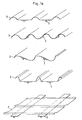
- FIG. 1 shows, for example, various sheet cross sections A, B, C, D, E of this type, the sheet metal strip being able to be deformed by folding or roll forming before the connection work, in order to be able to meet special static or aesthetic requirements.
- Both vertically structured sheet metal elements, FIG. 1 A - D, and horizontally structured sheet metal elements (FIG. 1 E) can be created.
- a permanently elastic heat-conducting paste 6 is applied and reduced to the optimum thickness using pressure (see FIG. 1 b).
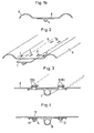
- So-called press rivets as shown in FIG. 2 and FIG. 3, serve as additional mechanical securing of the adhesive connection between sheet metal A and profile 1.
- the press rivets are carried out with special cutting press punches in order to ensure local punching with little deformation to achieve both components and a hooking 7-10 in the cutting area. '
- FIG. 4 Another mechanical fuse is shown in Figure 4; here threaded welding studs 11, 12 are welded on one side according to the capacitor discharge method without damaging the painted opposite side 13. Instead of a screw lock 14, a deformation of the upper bolt end can also take place here, so that the extruded profile 15 is held non-detachably.
- a further mechanical securing of the adhesive connection can take place by means of sheet metal strips 1.6, which are clamped in corresponding beads 18 formed in the sheet profile 17 and press the extruded profile 19 continuously by spring tension on the sheet profile.
- the sheet metal strips are advantageously folded on one side, since this considerably facilitates the pressing in (FIG. 5).
- the additional mechanical connections not only have the task of securing the adhesive connections against loosening, but are also intended to simplify the manufacturing process, since the glued components are thereby held in their position during the curing of the adhesive or the thermal paste can be packed right after the manufacturing process without paying particular attention to an outsourcing period.
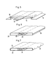
- FIG. 6 shows a further possibility of creating wide-area heat exchanger plates 20 which, for decorative purposes, must have visible surfaces which are closed on all sides. These are e.g. used for sun visors, privacy fences, soundproof walls, etc.
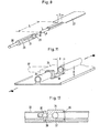
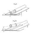
- a heat transfer fluid or a cooling fluid is introduced through the absorber extruded profiles. For this it is necessary to connect the components to each other and also to the distribution lines. This is done according to the invention in that, according to FIG. 8, the profile flanges 27 are removed at the end by sawing or punching to a limited length L and are then rounded off outside by means of special cutters, so that further pipe systems and pipe connecting elements can be connected.
- This special milling cutter is part of the overall system and, according to the invention, as shown in FIG. 8, consists of a cylindrical hollow body 28, which is provided with corresponding milling teeth on the end face 29 and carries an internal centering mandrel 30 at the opposite end, which at the same time also serves as a clamping mandrel in a hand drill or milling unit. It has proven to be advantageous to allow the centering mandrel to protrude approx. 10 mm beyond the end milling surface in order to obtain a locking mechanism when milling and thus to minimize the milling path.
- the milling sleeve 28 has longitudinal openings 31 so that cooling or lubricating liquids have access to the centering mandrel during the milling process. These longitudinal openings also serve for better chip removal.
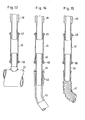
- FIGS. 9 and 10 A further possibility of obtaining a perfect round milling on such an extruded profile 32 without having to carry out prior removal of the profile flanges is shown in FIGS. 9 and 10.
- the distance A of the pipe center M from the flange surface 0 must be greater than half the pipe diameter d by at least the milling sleeve wall thickness s.
- the free pipe length can be increased in order to allow bending up to a bending angle ⁇ in order to be able to fasten corresponding pipe connection members.
- Figures 11 and 12 show a further possibility of profile formation.
- pressing the screw 35 with a slot or better with a hexagon socket in the nut washer 38 results in the fitting being pressed onto the sealing surface 36.
- the pipe connection 37 is rotated 90 ° to the longitudinal axis of the profile.
- a further innovation of the heat exchanger construction system consists in a simple combination of tube elements known per se, which enables simple and quick assembly of the individual, end-processed absorber profiles on the further distribution lines. So far it has been known that such multifunctional heat exchanger elements can be connected to the distribution lines by means of a rubber hose via hose clamps: Likewise known are connections which were created by means of commercially available cutting ring fittings. All connection systems have the disadvantage that considerable manual forces must be applied during assembly, the Ar increase workload unnecessarily. For safety reasons, please note: Hose clamps clamp the rubber hose so locally that it can be damaged and that the connection is not completely sealed.
- a pipe connection can be both rigid by means of a press fitting and with the interposition of elastic pipe members such as Rubber fabric hose or corrugated steel pipes can be created without having to have more than three components at hand.
- the rigid connection consists of a press fitting, FIG. 13, the cylindrical press fitting 41 being designed such that it can be pushed over the entire length continuously over the pipe element 42 to be connected with a sealing ring 49, 50.
- the inseparable connection is pressed using known electro-mechanical pressing tongs.
- elastic pipe members as shown in FIG. 14 and alternatively in FIG. 15, are interposed.
- a rubber fabric hose 43 is additionally required, in each of which a push-in pipe part 44 is pressed in at the end, which has a pipe cross-section 45 on one side and a fir tree-like toothing 46 on the other side of the pipe outside. The tightness is ensured by the tensile stresses occurring in the hose, slipping out of the insert tube part is prevented by the barbs of the fir-tree-like teeth.
- FIG. 15 Another possibility of a connection via an elastic pipe member is shown in FIG. 15.
- a corrugated metal hose 47 of relatively thin wall thickness is provided at the end with soldered or glued-in pipe parts 48, which in turn are connected by means of press fitting 41.
- the end of the metal-wide tube 47 is widened like a cup.
- the metal corrugated hose can also be provided on the inside with stiffening sleeves which enable a direct connection of the metal corrugated hose to the press fittings that can be pushed over.
- a sealing paste or the like is placed between the stiffening sleeve and the metal corrugated hose end before insertion.
Landscapes
- Engineering & Computer Science (AREA)
- Chemical & Material Sciences (AREA)
- Sustainable Energy (AREA)
- Life Sciences & Earth Sciences (AREA)
- Physics & Mathematics (AREA)
- Sustainable Development (AREA)
- Thermal Sciences (AREA)
- Combustion & Propulsion (AREA)
- Mechanical Engineering (AREA)
- General Engineering & Computer Science (AREA)
- Dispersion Chemistry (AREA)
- Heat-Exchange Devices With Radiators And Conduit Assemblies (AREA)
- Roof Covering Using Slabs Or Stiff Sheets (AREA)
- Extrusion Moulding Of Plastics Or The Like (AREA)
- Fencing (AREA)
Priority Applications (1)
| Application Number | Priority Date | Filing Date | Title |
|---|---|---|---|
| AT80107655T ATE9038T1 (de) | 1980-03-19 | 1980-12-05 | Waermetauscher fuer hausdaecher, fassaden, zaeune oder dergleichen. |
Applications Claiming Priority (2)
| Application Number | Priority Date | Filing Date | Title |
|---|---|---|---|
| DE3010523A DE3010523C2 (de) | 1980-03-19 | 1980-03-19 | Wärmetauscher für Hausdächer, Fassaden, Zäune o.dgl. |
| DE3010523 | 1980-03-19 |
Publications (3)
| Publication Number | Publication Date |
|---|---|
| EP0036041A2 true EP0036041A2 (fr) | 1981-09-23 |
| EP0036041A3 EP0036041A3 (en) | 1981-12-23 |
| EP0036041B1 EP0036041B1 (fr) | 1984-08-15 |
Family
ID=6097666
Family Applications (1)
| Application Number | Title | Priority Date | Filing Date |
|---|---|---|---|
| EP80107655A Expired EP0036041B1 (fr) | 1980-03-19 | 1980-12-05 | Echangeur de chaleur pour toits, façades, clôtures et similaires |
Country Status (4)
| Country | Link |
|---|---|
| EP (1) | EP0036041B1 (fr) |
| AT (1) | ATE9038T1 (fr) |
| DE (1) | DE3010523C2 (fr) |
| NO (1) | NO151133C (fr) |
Cited By (8)
| Publication number | Priority date | Publication date | Assignee | Title |
|---|---|---|---|---|
| EP0050180A1 (fr) * | 1980-10-16 | 1982-04-28 | Vereinigte Aluminium-Werke Aktiengesellschaft | Clôture absorbeuse utilisée comme échangeur de chaleur à grande surface |
| EP0841523A3 (fr) * | 1996-11-07 | 1999-07-07 | Friedrich Udo Müller | Absorbeur solaire comprenant des tronçons de tube ondulé |
| WO2000037861A1 (fr) * | 1998-12-22 | 2000-06-29 | Fraunhofer Gesellschaft zur Förderung der angewandten Forschung e.V. | Element de façade plan pouvant capter ou degager de l'energie thermique |
| EP1016835A3 (fr) * | 1998-12-18 | 2001-01-17 | Giuseppe Pullini | Système de connection hydraulique pour modules de collecteurs solaires et collecteurs solaires modulaires |
| EP2096376A3 (fr) * | 2008-02-07 | 2010-10-13 | Fundación Cidaut | Absorbeur métallique extrudé pour collecteur solaire |
| AT509724B1 (de) * | 2010-06-08 | 2011-11-15 | Thomas Ing Wolf | Fassadenelement für eine solarfassade |
| EP1746363A3 (fr) * | 2005-07-21 | 2013-04-24 | Deutsches Zentrum für Luft- und Raumfahrt e.V. | Récepteur solaire et procédé de contrôle et/ou de régulation de la répartition du débit et/ou de la compensation de température dans un récepteur solaire |
| EP2741043A1 (fr) | 2012-12-10 | 2014-06-11 | Peter Häusler | Agencement de profilé, procédé de fabrication de celui-ci, échangeur thermique, profilé de support et agencement d'échangeur thermique |
Families Citing this family (5)
| Publication number | Priority date | Publication date | Assignee | Title |
|---|---|---|---|---|
| DE3146659A1 (de) * | 1981-11-25 | 1983-06-23 | Gebrüder Uhl GmbH & Co KG, 7981 Vogt | "einrichtung zur uebertragung von waermeenergie" |
| DE3227326A1 (de) * | 1982-07-22 | 1984-01-26 | Karsten 7148 Remseck Laing | Druckloses grossflaechen-heizsystem |
| DE3617576A1 (de) * | 1986-05-24 | 1987-11-26 | Heraeus Wittmann Gmbh | Heizkoerperanordnung mit einem auf einem traeger befestigten rohr- oder schlauchfoermigen heizelement |
| DE3919143A1 (de) * | 1989-06-12 | 1990-12-13 | Turbon Tunzini Klimatechnik | Flaechenfoermiges waermeaustauschelement zum heizen und kuehlen von raeumen |
| DE202020100122U1 (de) * | 2020-01-10 | 2021-01-12 | Manfred Hampel | Energie-Schale sowie hiermit ausgestattetes Gebäude |
Family Cites Families (14)
| Publication number | Priority date | Publication date | Assignee | Title |
|---|---|---|---|---|
| DE7540889U (de) * | 1976-04-29 | Kabel- Und Metallwerke Gutehoffnungshuette Ag, 3000 Hannover | Metallische Abdeckplatte für Dächer | |
| GB769929A (en) * | 1954-12-14 | 1957-03-13 | Porter & Co Salford Ltd T | Improvements in and relating to heat exchangers |
| US3711130A (en) * | 1970-11-09 | 1973-01-16 | Air Prod & Chem | Ferruleless barbed tubing connector |
| DE7508887U (de) * | 1974-06-27 | 1976-08-12 | Schoell, Guenter, Prof. Dr.-Ing., Locarno-Muralto (Schweiz) | Sonnenkollektor |
| CH580734A5 (en) * | 1975-01-29 | 1976-10-15 | Schnyder Hans | Heat retaining swimming pool or other water cover - has flat buoyant bodies with translucent top facing light absorbent layer |
| AT370860B (de) * | 1976-07-23 | 1983-05-10 | Rudolf Doerwald | Einrichtung zur sonnenwaeremenutzung |
| DE2633862A1 (de) * | 1976-07-28 | 1978-02-02 | Walter Zink | Sonnenkollektor |
| US4098261A (en) * | 1977-02-23 | 1978-07-04 | Richard Edwin Watt | Flat plate solar collector panel having extruded thermal conductors |
| SE402640B (sv) * | 1977-06-13 | 1978-07-10 | Norell B | Byggmodul for innertak med inbyggda vermeelement |
| US4187901A (en) * | 1977-11-02 | 1980-02-12 | Beard Larry D | Flat plate solar heat collector |
| DE2756660B1 (de) * | 1977-12-19 | 1979-04-26 | Vaw Leichtmetall Gmbh | Waermetauscherrohr mit Anschlussstueck |
| DE2804301C2 (de) * | 1978-02-01 | 1983-12-01 | Werner 8032 Gräfelfing Veser | Sonnenkollektor für Dächer oder Fassaden von Gebäuden |
| DE2913490A1 (de) * | 1979-04-04 | 1981-03-26 | Vaw-Leichtmetall Gmbh, 5300 Bonn | Absorberdach |
| DE3003407A1 (de) * | 1980-01-31 | 1981-08-06 | Carlo Schaberger Sondermaschinenbau/Automationssysteme, 6500 Mainz | Verfahren zum herstellen einer gut waermeleitenden verbindung zwischen einer metallischen rohrleitung mit einem fluiden heiz- oder kuehlmedium und der aussenseite einer metallbehaelterwand |
-
1980
- 1980-03-19 DE DE3010523A patent/DE3010523C2/de not_active Expired
- 1980-12-05 AT AT80107655T patent/ATE9038T1/de not_active IP Right Cessation
- 1980-12-05 EP EP80107655A patent/EP0036041B1/fr not_active Expired
- 1980-12-23 NO NO803929A patent/NO151133C/no unknown
Cited By (8)
| Publication number | Priority date | Publication date | Assignee | Title |
|---|---|---|---|---|
| EP0050180A1 (fr) * | 1980-10-16 | 1982-04-28 | Vereinigte Aluminium-Werke Aktiengesellschaft | Clôture absorbeuse utilisée comme échangeur de chaleur à grande surface |
| EP0841523A3 (fr) * | 1996-11-07 | 1999-07-07 | Friedrich Udo Müller | Absorbeur solaire comprenant des tronçons de tube ondulé |
| EP1016835A3 (fr) * | 1998-12-18 | 2001-01-17 | Giuseppe Pullini | Système de connection hydraulique pour modules de collecteurs solaires et collecteurs solaires modulaires |
| WO2000037861A1 (fr) * | 1998-12-22 | 2000-06-29 | Fraunhofer Gesellschaft zur Förderung der angewandten Forschung e.V. | Element de façade plan pouvant capter ou degager de l'energie thermique |
| EP1746363A3 (fr) * | 2005-07-21 | 2013-04-24 | Deutsches Zentrum für Luft- und Raumfahrt e.V. | Récepteur solaire et procédé de contrôle et/ou de régulation de la répartition du débit et/ou de la compensation de température dans un récepteur solaire |
| EP2096376A3 (fr) * | 2008-02-07 | 2010-10-13 | Fundación Cidaut | Absorbeur métallique extrudé pour collecteur solaire |
| AT509724B1 (de) * | 2010-06-08 | 2011-11-15 | Thomas Ing Wolf | Fassadenelement für eine solarfassade |
| EP2741043A1 (fr) | 2012-12-10 | 2014-06-11 | Peter Häusler | Agencement de profilé, procédé de fabrication de celui-ci, échangeur thermique, profilé de support et agencement d'échangeur thermique |
Also Published As
| Publication number | Publication date |
|---|---|
| ATE9038T1 (de) | 1984-09-15 |
| NO803929L (no) | 1981-09-21 |
| DE3010523A1 (de) | 1981-10-01 |
| EP0036041B1 (fr) | 1984-08-15 |
| EP0036041A3 (en) | 1981-12-23 |
| NO151133C (no) | 1985-02-13 |
| NO151133B (no) | 1984-11-05 |
| DE3010523C2 (de) | 1985-09-12 |
Similar Documents
| Publication | Publication Date | Title |
|---|---|---|
| DE69526077T2 (de) | Rillenrohrkupplung und verbindungsverfahren | |
| DE2919848B1 (de) | Verbindung von Blechbahnen mit Schellen oder Hilfsblechen | |
| EP0036041B1 (fr) | Echangeur de chaleur pour toits, façades, clôtures et similaires | |
| EP2023059A1 (fr) | Cadre de montage destiné à l'application intégrée dans le bâtiment de modules photovoltaïques et collecteur solaire | |
| DE10044269A1 (de) | Klemmlasche | |
| DE2255747A1 (de) | Traeger, insbesondere deckentraeger fuer gebaeude | |
| DE2702939A1 (de) | Blechabdeckung fuer daecher | |
| EP2084340B1 (fr) | Revêtement, habillage ou analogue pour bâtiments ou parties de bâtiments | |
| AT406594B (de) | Montagesystem zur halterung von verkleidungselementen an bauwerken | |
| EP0447936B1 (fr) | Dispositif pour la fixation d'éléments d'installation | |
| EP1703214B1 (fr) | Elément de chauffage ou de réfrigération pour une cloison sèche avec ossature | |
| DE3610667A1 (de) | Doppelrohr bestehend aus zwei einstueckig ueber einen steg miteinander verbundenen schutzrohren | |
| EP2653792B1 (fr) | Profil conducteur de chaleur | |
| DE19828188C1 (de) | Fassadenprofil | |
| EP1278018B1 (fr) | Panneau | |
| EP1905919A2 (fr) | Profilé de recouvrement de socle | |
| AT519130B1 (de) | Kollektor für Strahlungsenergie | |
| DE102004023140A1 (de) | Moduldach, insbesondere für Hallen und Wohngebäude | |
| DE3128241C2 (de) | Verbolzung für Streckenausbaurahmen | |
| DE3713574A1 (de) | Glasflaeche mit daemmschicht | |
| AT389937B (de) | Sonnenkollektor sowie verfahren zur herstellung des kollektorelementes | |
| DE102023129393A1 (de) | Abstützelement und Gebäudeverkleidung | |
| DE102023000206A1 (de) | Profil, Profilanordnung und Temperierungssystem | |
| DE19909659C1 (de) | Verstrebung aus Metall | |
| DE19602075A1 (de) | Stahl-Fertiggarage, die statisch und stabilitätsmäßig beanspruchte Bauelemente aus Stahlblech aufweist |
Legal Events
| Date | Code | Title | Description |
|---|---|---|---|
| PUAI | Public reference made under article 153(3) epc to a published international application that has entered the european phase |
Free format text: ORIGINAL CODE: 0009012 |
|
| AK | Designated contracting states |
Designated state(s): AT BE CH FR GB IT LI LU NL SE |
|
| PUAL | Search report despatched |
Free format text: ORIGINAL CODE: 0009013 |
|
| AK | Designated contracting states |
Designated state(s): AT BE CH FR GB IT LI LU NL SE |
|
| 17P | Request for examination filed |
Effective date: 19820618 |
|
| RAP1 | Party data changed (applicant data changed or rights of an application transferred) |
Owner name: VEREINIGTE ALUMINIUMWERKE AKTIENGESELLSCHAFT |
|
| ITF | It: translation for a ep patent filed | ||
| GRAA | (expected) grant |
Free format text: ORIGINAL CODE: 0009210 |
|
| AK | Designated contracting states |
Designated state(s): AT BE CH FR GB IT LI LU NL SE |
|
| REF | Corresponds to: |
Ref document number: 9038 Country of ref document: AT Date of ref document: 19840915 Kind code of ref document: T |
|
| ET | Fr: translation filed | ||
| PLBE | No opposition filed within time limit |
Free format text: ORIGINAL CODE: 0009261 |
|
| STAA | Information on the status of an ep patent application or granted ep patent |
Free format text: STATUS: NO OPPOSITION FILED WITHIN TIME LIMIT |
|
| 26N | No opposition filed | ||
| ITTA | It: last paid annual fee | ||
| PGFP | Annual fee paid to national office [announced via postgrant information from national office to epo] |
Ref country code: GB Payment date: 19911121 Year of fee payment: 12 |
|
| PGFP | Annual fee paid to national office [announced via postgrant information from national office to epo] |
Ref country code: FR Payment date: 19911127 Year of fee payment: 12 |
|
| PGFP | Annual fee paid to national office [announced via postgrant information from national office to epo] |
Ref country code: BE Payment date: 19911129 Year of fee payment: 12 |
|
| PGFP | Annual fee paid to national office [announced via postgrant information from national office to epo] |
Ref country code: SE Payment date: 19911205 Year of fee payment: 12 Ref country code: AT Payment date: 19911205 Year of fee payment: 12 |
|
| PGFP | Annual fee paid to national office [announced via postgrant information from national office to epo] |
Ref country code: LU Payment date: 19911206 Year of fee payment: 12 |
|
| PGFP | Annual fee paid to national office [announced via postgrant information from national office to epo] |
Ref country code: NL Payment date: 19911231 Year of fee payment: 12 |
|
| PGFP | Annual fee paid to national office [announced via postgrant information from national office to epo] |
Ref country code: CH Payment date: 19920212 Year of fee payment: 12 |
|
| EPTA | Lu: last paid annual fee | ||
| PG25 | Lapsed in a contracting state [announced via postgrant information from national office to epo] |
Ref country code: LU Free format text: LAPSE BECAUSE OF NON-PAYMENT OF DUE FEES Effective date: 19921205 Ref country code: GB Effective date: 19921205 Ref country code: AT Effective date: 19921205 |
|
| PG25 | Lapsed in a contracting state [announced via postgrant information from national office to epo] |
Ref country code: SE Effective date: 19921206 |
|
| PG25 | Lapsed in a contracting state [announced via postgrant information from national office to epo] |
Ref country code: LI Effective date: 19921231 Ref country code: CH Effective date: 19921231 Ref country code: BE Effective date: 19921231 |
|
| BERE | Be: lapsed |
Owner name: VEREINIGTE ALUMINIUM-WERKE A.G. Effective date: 19921231 |
|
| PG25 | Lapsed in a contracting state [announced via postgrant information from national office to epo] |
Ref country code: NL Effective date: 19930701 |
|
| GBPC | Gb: european patent ceased through non-payment of renewal fee |
Effective date: 19921205 |
|
| NLV4 | Nl: lapsed or anulled due to non-payment of the annual fee | ||
| PG25 | Lapsed in a contracting state [announced via postgrant information from national office to epo] |
Ref country code: FR Effective date: 19930831 |
|
| REG | Reference to a national code |
Ref country code: CH Ref legal event code: PL |
|
| REG | Reference to a national code |
Ref country code: FR Ref legal event code: ST |
|
| EUG | Se: european patent has lapsed |
Ref document number: 80107655.5 Effective date: 19930709 |