EP0036115A2 - Installation de commande centralisée à audio-fréquence avec dispositif de surveillance de courant - Google Patents
Installation de commande centralisée à audio-fréquence avec dispositif de surveillance de courant Download PDFInfo
- Publication number
- EP0036115A2 EP0036115A2 EP81101416A EP81101416A EP0036115A2 EP 0036115 A2 EP0036115 A2 EP 0036115A2 EP 81101416 A EP81101416 A EP 81101416A EP 81101416 A EP81101416 A EP 81101416A EP 0036115 A2 EP0036115 A2 EP 0036115A2
- Authority
- EP
- European Patent Office
- Prior art keywords
- inverter
- voltage
- phase
- current
- frequency
- Prior art date
- Legal status (The legal status is an assumption and is not a legal conclusion. Google has not performed a legal analysis and makes no representation as to the accuracy of the status listed.)
- Granted
Links
Images
Classifications
-
- H—ELECTRICITY
- H02—GENERATION; CONVERSION OR DISTRIBUTION OF ELECTRIC POWER
- H02J—ELECTRIC POWER NETWORKS; CIRCUIT ARRANGEMENTS OR SYSTEMS FOR SUPPLYING OR DISTRIBUTING ELECTRIC POWER; SYSTEMS FOR STORING ELECTRIC ENERGY
- H02J13/00—Circuit arrangements for providing remote monitoring or remote control of equipment in a power distribution network
- H02J13/13—Circuit arrangements for providing remote monitoring or remote control of equipment in a power distribution network characterised by the transmission of data to equipment in the power network
- H02J13/1311—Circuit arrangements for providing remote monitoring or remote control of equipment in a power distribution network characterised by the transmission of data to equipment in the power network using the power network as support for the transmission
- H02J13/1313—Circuit arrangements for providing remote monitoring or remote control of equipment in a power distribution network characterised by the transmission of data to equipment in the power network using the power network as support for the transmission using pulsed signals
-
- Y—GENERAL TAGGING OF NEW TECHNOLOGICAL DEVELOPMENTS; GENERAL TAGGING OF CROSS-SECTIONAL TECHNOLOGIES SPANNING OVER SEVERAL SECTIONS OF THE IPC; TECHNICAL SUBJECTS COVERED BY FORMER USPC CROSS-REFERENCE ART COLLECTIONS [XRACs] AND DIGESTS
- Y02—TECHNOLOGIES OR APPLICATIONS FOR MITIGATION OR ADAPTATION AGAINST CLIMATE CHANGE
- Y02B—CLIMATE CHANGE MITIGATION TECHNOLOGIES RELATED TO BUILDINGS, e.g. HOUSING, HOUSE APPLIANCES OR RELATED END-USER APPLICATIONS
- Y02B90/00—Enabling technologies or technologies with a potential or indirect contribution to GHG emissions mitigation
- Y02B90/20—Smart grids as enabling technology in buildings sector
-
- Y—GENERAL TAGGING OF NEW TECHNOLOGICAL DEVELOPMENTS; GENERAL TAGGING OF CROSS-SECTIONAL TECHNOLOGIES SPANNING OVER SEVERAL SECTIONS OF THE IPC; TECHNICAL SUBJECTS COVERED BY FORMER USPC CROSS-REFERENCE ART COLLECTIONS [XRACs] AND DIGESTS
- Y02—TECHNOLOGIES OR APPLICATIONS FOR MITIGATION OR ADAPTATION AGAINST CLIMATE CHANGE
- Y02E—REDUCTION OF GREENHOUSE GAS [GHG] EMISSIONS, RELATED TO ENERGY GENERATION, TRANSMISSION OR DISTRIBUTION
- Y02E60/00—Enabling technologies; Technologies with a potential or indirect contribution to GHG emissions mitigation
-
- Y—GENERAL TAGGING OF NEW TECHNOLOGICAL DEVELOPMENTS; GENERAL TAGGING OF CROSS-SECTIONAL TECHNOLOGIES SPANNING OVER SEVERAL SECTIONS OF THE IPC; TECHNICAL SUBJECTS COVERED BY FORMER USPC CROSS-REFERENCE ART COLLECTIONS [XRACs] AND DIGESTS
- Y04—INFORMATION OR COMMUNICATION TECHNOLOGIES HAVING AN IMPACT ON OTHER TECHNOLOGY AREAS
- Y04S—SYSTEMS INTEGRATING TECHNOLOGIES RELATED TO POWER NETWORK OPERATION, COMMUNICATION OR INFORMATION TECHNOLOGIES FOR IMPROVING THE ELECTRICAL POWER GENERATION, TRANSMISSION, DISTRIBUTION, MANAGEMENT OR USAGE, i.e. SMART GRIDS
- Y04S40/00—Systems for electrical power generation, transmission, distribution or end-user application management characterised by the use of communication or information technologies, or communication or information technology specific aspects supporting them
- Y04S40/12—Systems for electrical power generation, transmission, distribution or end-user application management characterised by the use of communication or information technologies, or communication or information technology specific aspects supporting them characterised by data transport means between the monitoring, controlling or managing units and monitored, controlled or operated electrical equipment
- Y04S40/121—Systems for electrical power generation, transmission, distribution or end-user application management characterised by the use of communication or information technologies, or communication or information technology specific aspects supporting them characterised by data transport means between the monitoring, controlling or managing units and monitored, controlled or operated electrical equipment using the power network as support for the transmission
Definitions
- the invention relates to an audio frequency ripple control system with the features specified in the preamble of claim 1.
- Such a ripple control system is known from German Offenlegungsschrift 27 50 394.
- Encrypted information is sent as a pulse train via a three-phase or an AC supply network to consumers, where it is decrypted and used for switching processes, e.g. to switch consumer meters to different tariffs or to switch on signaling devices to notify certain groups of people (fire brigade), serve.
- switching processes e.g. to switch consumer meters to different tariffs or to switch on signaling devices to notify certain groups of people (fire brigade), serve.
- Usually low-frequency vibrations in the frequency range between 150 Hz and 500 Hz are used for the duration of given clock pulses.
- these frequencies are generated with an inverter and advantageously superimposed on the network frequency by series injection into the network.
- a DC input voltage is impressed on the inverter input, which is given to the two (alternating current network), three (three-phase network) or more phase outputs of the inverter by appropriately firing the inverter valves with the transmission tone frequency in the form of voltage blocks of 180 ° length with alternating signs.
- longitudinal inductances and an adaptation transformer are advantageously connected downstream of the outputs. These inductors are designed to be as small as possible to ensure good harmonic damping to cause and cause excessive voltage drops under load.
- the series feed of the transmission frequency is done by current transformers whose triangular primary windings are connected to the phase voltages and their secondary windings in the supply network.
- filter circuits are arranged, which are designed as three-phase filters to protect the inverter from the effects of the mains frequency by means of a small alternating current resistor for the grid frequency and, on the other hand, to transmit this tone frequency to the current transformers with as little loss as possible using a large AC resistor for the tone frequency.
- Each phase voltage thus contains a tone-frequency fundamental and harmonics, the harmonics being smoothed by the series inductors and, if necessary, the matching transformer and, as a result of resonance oscillations in the filter circuits, being supplied to the converter inputs almost as a sinusoidal voltage.
- the amplitude of the fundamental frequency can be determined by the switch-on-time ratio of the respective inverter valves of a phase output, ie by the Voltage time area of the corresponding phase voltage can be changed. This makes it possible, by appropriately controlling the switch-on ratio, to slowly ramp up the pulse-controlled inverter to full output power at the start of each transmission cycle, so that impermissibly high switch-on current peaks are avoided.
- a monitoring device which detects the phase currents between the inverter and the filter circuits and, when a predetermined current limit value is exceeded, intervenes in the ignition control of the inverter in such a way that the amplitude of the tone-frequency phase voltages is reduced by reducing the voltage time areas will then gradually ramp up the transmitter to full output, as in the start-up process. It has now been shown in some cases that, in the case of such a system, in which, when the monitoring system responds in the sense of a reduction in the transmission power in the ignition control of all inverter valves, the monitoring system often responds in succession.
- the transmitter can then only be started up to maximum power very slowly or not at all, where if there is a risk that the reduced transmission power is no longer sufficient to transmit the transmission signals to the receivers (consumers). This can occur, for example, if the overcurrent peaks are not caused by temporary faults. In particular, this occurs when the filter circuits are short-circuited during the pauses in transmission by corresponding switches that are opened at the start of a transmission cycle. Such switches are advantageous, for example, around the filter circuits. to relieve during the breaks.
- the invention has for its object to provide a ripple control transmitter with the features specified in the preamble of claim 1 so that not only can react to peak currents by another intervention in the inverter control, but also a possible cause for their occurrence is corrected itself.
- the invention is intended to improve the operation of a ripple control system, the filters of which are short-circuitable due to the switches mentioned during the transmission pauses.
- the converter coils of such a ripple control system are often magnetized at the start of a transmission cycle.
- a bias occurs when the switches are opened at the start of the transmission cycle.
- the premagnetization is noticeable in the fact that the approximately sinusoidal time course of the magnetic flux in the transducers (measurable as a time integral of the supply voltage impressed on the transducer coils) is shifted from the center of the hysteresis characteristics of the transducer coils.
- the converters are always driven into saturation on every second half-wave of the tonfrcquent supply voltage, so that there is an increased current consumption comes to the inverter.
- the invention is therefore based on the idea that when such a peak current occurs at the converter output, not only does the purging time area of the corresponding tone-frequency phase output voltage half-wave (and thus the instantaneous output current) to protect the inverter, but also the cause, namely the premagnetization of the converter fight.
- the monitoring device issues an intervention command assigned to the relevant inverter output.
- This command only intervenes in the control of the inverter valves working on this output, the control of the other inverter valves remains unaffected.
- the intervention takes place in such a way that the phase voltage present at the assigned output contains a direct voltage component which leads to a demagnetizing direct current component in the converter coils which reduces the premagnetization.
- the polarity of this DC component is opposite to the peak current, so that at the same time the peak current which triggers the intervention command is reduced.
- a similar procedure can also be used if the tone-frequency fundamental oscillation of the phase voltage is generated by repeated alternate firing of the inverter valves (back and forth pulsing of the phase output voltage between two voltage values of opposite sign) within each audio frequency half-wave.
- This case occurs in particular during the start-up process in the known device, where the amplitude of the audio frequency is slowly ramped up by a corresponding pulse operation.
- a positive current peak during such a run-up meets an operating state of the inverter, in which the inverter output is connected to the positive polarity of the input voltage by carrying the current of the corresponding inverter valve.
- the intervention command then causes this valve to be blocked and the inverter output is temporarily set to negative voltage by firing the other valve.
- the chip time area of the positive tone-frequency half-wave is thereby reduced compared to the value which is provided for an undisturbed start-up and approximately corresponds to the mean value of the previous and subsequent negative half-waves.
- the duration during which the other valve is to be fired in order to generate the direct voltage component must not be less than a certain value which corresponds to the lowest possible current carrying duration of the inverter.
- a particularly simple control is obtained if the duration of the voltage changeover explained is constant over this minimum current carrying duration of the change rectifier is held. With each intervention command, the voltage time period is reduced by an amount that is independent of the duration of the current limit value being exceeded.
- intervention occurs only once, and the further ignition control is left undisturbed.
- phase current again exceeds the limit value after a single intervention, this leads to a new intervention command and the corrective action is repeated.
- the transformer pre-magnetization cannot be remedied in one step or if the overcurrents are not caused by the premagnetization of the current transformers but by other processes.
- the peak currents can occur in all phase outputs and both during the positive and during the negative tone sequence half-circuits. This then leads to corresponding intervention commands occurring for all phase outputs and with all polarities and the overall amplitude of the audio frequency oscillation being reduced overall.
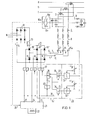
- a sound-frequency alternating voltage is impressed on the phases R, S, T of a three-phase supply network.
- the primary coils of converter transformers are placed in the AC lines, the secondary coils 1, 2, 3 of which are connected in a triangle.
- The. Inputs of these current transformer coils 1, 2, 3 are each connected to an output 5, 6, 7 of an inverter via inductors 4, the inverter transformer 8 being used for electrical isolation and for adapting the voltages.
- the filter circuits of a three-phase filter 9 which is constructed in the manner shown from capacitors and inductors.
- a switching device comprising switches 10a, 10b, 10c is also advantageously provided, by means of which the connections of a coil can be connected to one another, so that the filter circuits can be short-circuited.
- the inverter 11 serves as the transmitter for the tone-residual voltages in the inverter output phases 5, 6, 7, the DC voltage side of which is embossed with a specifiable input DC voltage via a mains-operated rectifier 12 and a parallel capacitor 13 from a low-frequency AC voltage network N.
- the self-commutated inverter 11 is preferably a bridge-type inverter with pulsed operation, the outputs of which are triggered by firing the associated valves 16, 17, 18 of each jumper branch to the voltage at the positive input terminal 14 or when the other valves 16 'are live, 17 ', 18' be connected to the negative input potential of terminal 15.
- the length of the transmission clocks and transmission pauses for the audio frequency to be transmitted are specified via a line 20 of an ignition control 21 which forms the inverter ignition pulses from the pulses of a generator device 22 which is tuned to the audio frequency or a multiple of the audio frequency.
- an ignition control 21 which forms the inverter ignition pulses from the pulses of a generator device 22 which is tuned to the audio frequency or a multiple of the audio frequency.
- corresponding voltage pulses are applied to the ignition control lines 23, 24, 25, from which the (not shown) control units of the valves 16, ..., 18 'form the ignition pulses for the inverter valves.
- the parts of the plant according to FIG. 1 described so far can be designed, for example, in the manner specified in DE-AS 24 56 344.
- the control device generates a voltage for each bridge branch, which alternately assumes the values + U 0 and - U 0 as a result of binary signals.
- Such a binary signal sequence on the control line 23 causes the valve 16 to be fired for voltage values + U 0 ("1" state).
- the other valve 16 'of this bridge branch is energized analogously by the voltage values - U 0 ("0" state).
- the voltage at the inverter output phase 5 follows this voltage curve.
- pulse width modulation can be carried out in which the fundamental oscillation U TF of the phase voltage and thus also the fundamental oscillation of the voltage time areas have the tone frequency.
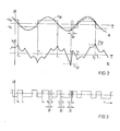
- the amplitude of the oscillation U TF is increased by changing the pulse width modulation until the phase voltage is composed of voltage blocks of 180 ° el width at maximum output power (FIG. 2).
- This well-known Pulse width modulation is also advantageous for the inverter 11.
- FIG. 2b shows the course of the current 5 in the inverter output phase 5.
- T + and t - are the switching times predetermined by the ignition control, at which the phase saving is reversed by igniting the valve 16 or 16 '. It can now happen that at certain points in time (t 1 , t 2 ) the current in phase 5 exceeds a predefined limit value + i gr or - i gr , the limit value being predefined such that reliable commutation in Inverter is possible. If this limit value is exceeded, the inverter control must be intervened.
- each individual phase current is monitored separately in the monitoring device 28 (FIG. 1) for exceeding the limit value i gr .
- the monitoring device thus has three symmetrical branches, one of which is assigned to the current transformer 25 or 26 or 27 and is only shown in FIG. 1 for the sake of clarity, and is explained below.
- the monitoring device 28 If the limit value for the phase current 15 is exceeded, the monitoring device 28 generates an intervention command at the command routing lines 29, 29 ', by means of which the valves 16, 16' of the bridge branch working on the phase input 5 are switched over to the undisturbed operation.
- the duration of the switchover is advantageously selected independently of the duration of the current limit value being exceeded.
- Timers can be used for this, which are matched to the shortest possible current carrying time of the inverter valves.
- Conventional pulse inverter controls already contain a circuit for suppressing switching commands that follow one another too quickly, so that no further timing elements are required for the execution of the intervention command.
- FIG. 1 schematically shows a circuit which can be connected between the ignition control output of an existing inverter control and the control devices for the corresponding valves 16, 16 '.
- the output signal of the current transformer 25 is advantageously monitored with separate limit value detectors 32, 33 for exceeding a positive limit value + i gr or a negative limit value - i gr .
- the OR gate 36 downstream of the multivibrators gives one Zero state at the corresponding input of an EXCLUSIVE-OR gate 37 located in the control line 23.
- the states (0 and 1) coming from the controller 21 are therefore passed unchanged via the gate 37 to the ignitors of the valves 16, 16 ' .
- This undisturbed operation is shown in FIG. 2 before the time t 1 , the response of the limit indicator 32 for falling below the negative limit.
- the flip-flop 34 can be locked by the line 33 in such a way that the limit detector 32 assigned to the positive limit value only generates a 1-state of the flip-flop 34 if a 1-state is present on the signal line 23, that is to say if the operation of the current is undisturbed Valve 16 the phase voltage is positive.
- the flip-flop 34 remains in the 1 state for the set minimum time if no polarity change occurs in the meantime in the signal line 23; however, if the state on the signal line 23 prematurely changes to the zero state, the 1 state at the output of the flip-flop 34 is also ended prematurely.
- the output of the flip-flop assigned to the negative limit violation (limit value detector 33) is kept in the zero state via the locking line 39 and the negation element 40 when the signal line 23 is in a zero state.
- the EXCLUSIVE-OR gate 37 whose inputs are now both in the 1 state, triggers the limit alarm 32 and the trigger circuit 34 Generated zero state, by which the valve 16 is blocked and the valve 16 'is ignited. A negative voltage is now present at inverter output 5.
- the state on the command line 23 changes to the zero state within the minimum time ⁇ t, as a result of which the flip-flop 35 tilts back and the EXCLUSIVE-OR gate 37 now receives a zero signal at both inputs.
- the output of the link 37 thus remains in the zero state and the valves are controlled further in accordance with the undisturbed operation.
- FIG. 2a shows the change in the smoothed phase voltage U TF compared to the undisturbed curve shown in broken lines.
- the same method can also be used for pulse operation of the inverter, as shown in FIG. 3.
- the times specified by the ignition controller 21 for the undisturbed operation for igniting the valve 16 or 16 ′ are shown with t and t_.
- t 1 , t 2 and t 3 limit values are exceeded and the polarity of the output voltage reversed. Analogously to FIG. 2, this is done on the Intervention command t 1 following. Changeover command t - only after the intervention time ⁇ t. With intervention t 2 , however, the next switching command t falls within the intervention time ⁇ t and is therefore suppressed, as has already been explained with reference to FIG. 2.
- next changeover command t + occurs after the end of the intervention time ⁇ t, but the time remaining after the end of the intervention (time t 3 + ⁇ t ) until the next changeover command t + would be less than the minimum current duration of the inverter valves.
- a minimum time lock is provided for commercially available inverters, by means of which the time for the next switchover t + is correspondingly delayed.
- the circuit unit 40 for carrying out the command intervention can of course also be implemented using other logic components. It can be arranged downstream of the limit value detectors 32, 33 and integrated with the monitoring device 28, but it can also be integrated with the inverter control 21 and only connected to the monitoring device via the command inputs 29, 29 '.
Landscapes
- Engineering & Computer Science (AREA)
- Power Engineering (AREA)
- Inverter Devices (AREA)
- Cable Transmission Systems, Equalization Of Radio And Reduction Of Echo (AREA)
Applications Claiming Priority (2)
| Application Number | Priority Date | Filing Date | Title |
|---|---|---|---|
| DE3008480 | 1980-03-05 | ||
| DE19803008480 DE3008480A1 (de) | 1980-03-05 | 1980-03-05 | Tonfrequenz-rundsteueranlage mit einer stromueberwachungseinrichtung |
Publications (4)
| Publication Number | Publication Date |
|---|---|
| EP0036115A2 true EP0036115A2 (fr) | 1981-09-23 |
| EP0036115A3 EP0036115A3 (en) | 1981-10-07 |
| EP0036115B1 EP0036115B1 (fr) | 1983-10-05 |
| EP0036115B2 EP0036115B2 (fr) | 1987-11-19 |
Family
ID=6096369
Family Applications (1)
| Application Number | Title | Priority Date | Filing Date |
|---|---|---|---|
| EP81101416A Expired EP0036115B2 (fr) | 1980-03-05 | 1981-02-26 | Installation de commande centralisée à audio-fréquence avec dispositif de surveillance de courant |
Country Status (6)
| Country | Link |
|---|---|
| US (1) | US4365286A (fr) |
| EP (1) | EP0036115B2 (fr) |
| JP (1) | JPS56138345A (fr) |
| AU (1) | AU6806081A (fr) |
| DE (2) | DE3008480A1 (fr) |
| ZA (1) | ZA811432B (fr) |
Families Citing this family (1)
| Publication number | Priority date | Publication date | Assignee | Title |
|---|---|---|---|---|
| US4642747A (en) * | 1985-05-22 | 1987-02-10 | Westinghouse Electric Corp. | Fault-protection apparatus for static AC-to-AC converters and unrestricted frequency changer (UFC) system including such fault-protection apparatus |
Family Cites Families (4)
| Publication number | Priority date | Publication date | Assignee | Title |
|---|---|---|---|---|
| US3898531A (en) * | 1974-01-25 | 1975-08-05 | Westinghouse Electric Corp | Segregated phase comparison relaying apparatus |
| CH581918A5 (fr) * | 1974-07-16 | 1976-11-15 | Zellweger Uster Ag | |
| DE2456344C3 (de) * | 1974-11-28 | 1983-04-14 | Siemens AG, 1000 Berlin und 8000 München | Tonfrequenz-Rundsteueranlage |
| DE2750394C3 (de) * | 1977-11-10 | 1983-11-17 | Siemens AG, 1000 Berlin und 8000 München | Tonfrequenz-Rundsteueranlage mit einem Wechselrichter als Tonfrequenz- Rundsteuersender |
-
1980
- 1980-03-05 DE DE19803008480 patent/DE3008480A1/de not_active Withdrawn
-
1981
- 1981-02-26 DE DE8181101416T patent/DE3161074D1/de not_active Expired
- 1981-02-26 EP EP81101416A patent/EP0036115B2/fr not_active Expired
- 1981-03-03 US US06/239,976 patent/US4365286A/en not_active Expired - Fee Related
- 1981-03-04 AU AU68060/81A patent/AU6806081A/en not_active Abandoned
- 1981-03-04 ZA ZA00811432A patent/ZA811432B/xx unknown
- 1981-03-05 JP JP3189381A patent/JPS56138345A/ja active Pending
Also Published As
| Publication number | Publication date |
|---|---|
| EP0036115B1 (fr) | 1983-10-05 |
| ZA811432B (en) | 1982-03-31 |
| EP0036115B2 (fr) | 1987-11-19 |
| DE3161074D1 (en) | 1983-11-10 |
| DE3008480A1 (de) | 1981-09-10 |
| EP0036115A3 (en) | 1981-10-07 |
| JPS56138345A (en) | 1981-10-28 |
| US4365286A (en) | 1982-12-21 |
| AU6806081A (en) | 1981-09-10 |
Similar Documents
| Publication | Publication Date | Title |
|---|---|---|
| DE2923471C2 (fr) | ||
| DE69219761T2 (de) | Vorrichtung und Regelmethode zum Starten und Stoppen eines Dreiphasen-Induktionsmotors | |
| EP1251991A1 (fr) | Procede pour la regulation et/ou la commande d'une source de courant de soudage grace a un circuit a resonance | |
| CH493131A (de) | Verfahren zum Übertragen von Steuersignalen über ein Wechselstromnetz und Rundsteuerungsanlage zur Ausführung des Verfahrens | |
| DE9409760U1 (de) | Schaltungsanordnung zur Ansteuerung eines Schützes | |
| WO1993008628A1 (fr) | Procede et dispositif visant a eviter les surintensites dans un convertisseur de frequence de soudage | |
| DE2456344C3 (de) | Tonfrequenz-Rundsteueranlage | |
| DE19504271C1 (de) | Verfahren und Vorrichtung zur Impedanzmessung in Wechselstromnetzen sowie Verfahren und Vorrichtung zur Verhinderung von Inselnetzen | |
| DE3151241A1 (de) | Leistungsgesteuerter stromgenerator | |
| DE2023715A1 (de) | Gesteuerte Antriebsvorrichtung der Wäschetrommel einer Waschmaschine | |
| EP0466738B1 (fr) | Procede pour limiter le courant alternatif d'allumage | |
| EP0037087B1 (fr) | Procédé et dispositif pour brancher et débrancher sans suroscillation un condensateur entre deux conducteurs d'un réseau à tension alternative | |
| DE3512834C2 (fr) | ||
| EP0036115B1 (fr) | Installation de commande centralisée à audio-fréquence avec dispositif de surveillance de courant | |
| DE4011170A1 (de) | Vorrichtung zur wechselstrom-einschaltbegrenzung | |
| DE69508577T2 (de) | Rückgewinnung von übertragener leistung in einer installation zur übertragung von hochspannungsgleichstrom | |
| DE10101988B4 (de) | Schaltungsanordnung zum Schutz eines Verbrauchers vor Überspannungen | |
| EP0313542B1 (fr) | Dispositif d'enclenchement contrôlé d'éléments inductifs dans le réseau haute tension | |
| EP0783702B1 (fr) | Procede et dispositif de mesure d'impedance dans des reseaux a courant alternatif, ainsi que procede et dispositif pour empecher la formation de reseaux separes | |
| AT240948B (de) | Verfahren und Schaltungsanordnung zur selektiven Erfassung von Erdschlußwischern und Dauererdschlüssen | |
| DE2446390C3 (de) | Verfahren und Schaltungsanordnung zum phasenrichtigen Start eines statischen Wechselrichters mit Zwangskommutierung | |
| DE659506C (de) | Parallelschalteinrichtung | |
| DE1236562B (de) | Impulsgenerator zur Erzeugung von Impulsen entgegengesetzter Polaritaet | |
| DE2745586A1 (de) | Stromversorgungsschaltung mit umschaltbaren transformatoranzapfungen | |
| CH420341A (de) | Einrichtung zur Fernübertragung von Signalen über ein Versorgungsnetz für elektrische Energie |
Legal Events
| Date | Code | Title | Description |
|---|---|---|---|
| PUAI | Public reference made under article 153(3) epc to a published international application that has entered the european phase |
Free format text: ORIGINAL CODE: 0009012 |
|
| PUAL | Search report despatched |
Free format text: ORIGINAL CODE: 0009013 |
|
| AK | Designated contracting states |
Designated state(s): CH DE FR |
|
| AK | Designated contracting states |
Designated state(s): CH DE FR |
|
| 17P | Request for examination filed |
Effective date: 19810907 |
|
| GRAA | (expected) grant |
Free format text: ORIGINAL CODE: 0009210 |
|
| AK | Designated contracting states |
Designated state(s): CH DE FR LI |
|
| REF | Corresponds to: |
Ref document number: 3161074 Country of ref document: DE Date of ref document: 19831110 |
|
| ET | Fr: translation filed | ||
| PLBI | Opposition filed |
Free format text: ORIGINAL CODE: 0009260 |
|
| 26 | Opposition filed |
Opponent name: AEG-TELEFUNKEN AKTIENGESELLSCHAFT, BERLIN UND FRAN Effective date: 19840630 |
|
| PUAH | Patent maintained in amended form |
Free format text: ORIGINAL CODE: 0009272 |
|
| STAA | Information on the status of an ep patent application or granted ep patent |
Free format text: STATUS: PATENT MAINTAINED AS AMENDED |
|
| 27A | Patent maintained in amended form |
Effective date: 19871119 |
|
| AK | Designated contracting states |
Kind code of ref document: B2 Designated state(s): CH DE FR LI |
|
| ET3 | Fr: translation filed ** decision concerning opposition | ||
| PGFP | Annual fee paid to national office [announced via postgrant information from national office to epo] |
Ref country code: FR Payment date: 19930219 Year of fee payment: 13 |
|
| PGFP | Annual fee paid to national office [announced via postgrant information from national office to epo] |
Ref country code: DE Payment date: 19930422 Year of fee payment: 13 |
|
| PGFP | Annual fee paid to national office [announced via postgrant information from national office to epo] |
Ref country code: CH Payment date: 19930519 Year of fee payment: 13 |
|
| PG25 | Lapsed in a contracting state [announced via postgrant information from national office to epo] |
Ref country code: LI Effective date: 19940228 Ref country code: CH Effective date: 19940228 |
|
| PG25 | Lapsed in a contracting state [announced via postgrant information from national office to epo] |
Ref country code: FR Effective date: 19941031 |
|
| REG | Reference to a national code |
Ref country code: CH Ref legal event code: PL |
|
| PG25 | Lapsed in a contracting state [announced via postgrant information from national office to epo] |
Ref country code: DE Effective date: 19941101 |
|
| REG | Reference to a national code |
Ref country code: FR Ref legal event code: ST |