EP0036177B1 - Gasfluidisierbarer Luftvorwärmer - Google Patents
Gasfluidisierbarer Luftvorwärmer Download PDFInfo
- Publication number
- EP0036177B1 EP0036177B1 EP81101788A EP81101788A EP0036177B1 EP 0036177 B1 EP0036177 B1 EP 0036177B1 EP 81101788 A EP81101788 A EP 81101788A EP 81101788 A EP81101788 A EP 81101788A EP 0036177 B1 EP0036177 B1 EP 0036177B1
- Authority
- EP
- European Patent Office
- Prior art keywords
- air
- gas
- tubes
- stage
- warm
- Prior art date
- Legal status (The legal status is an assumption and is not a legal conclusion. Google has not performed a legal analysis and makes no representation as to the accuracy of the status listed.)
- Expired
Links
Images

Classifications
-
- F—MECHANICAL ENGINEERING; LIGHTING; HEATING; WEAPONS; BLASTING
- F23—COMBUSTION APPARATUS; COMBUSTION PROCESSES
- F23L—SUPPLYING AIR OR NON-COMBUSTIBLE LIQUIDS OR GASES TO COMBUSTION APPARATUS IN GENERAL ; VALVES OR DAMPERS SPECIALLY ADAPTED FOR CONTROLLING AIR SUPPLY OR DRAUGHT IN COMBUSTION APPARATUS; INDUCING DRAUGHT IN COMBUSTION APPARATUS; TOPS FOR CHIMNEYS OR VENTILATING SHAFTS; TERMINALS FOR FLUES
- F23L15/00—Heating of air supplied for combustion
- F23L15/04—Arrangements of recuperators
- F23L15/045—Arrangements of recuperators using intermediate heat-transfer fluids
-
- B—PERFORMING OPERATIONS; TRANSPORTING
- B01—PHYSICAL OR CHEMICAL PROCESSES OR APPARATUS IN GENERAL
- B01J—CHEMICAL OR PHYSICAL PROCESSES, e.g. CATALYSIS OR COLLOID CHEMISTRY; THEIR RELEVANT APPARATUS
- B01J8/00—Chemical or physical processes in general, conducted in the presence of fluids and solid particles; Apparatus for such processes
- B01J8/18—Chemical or physical processes in general, conducted in the presence of fluids and solid particles; Apparatus for such processes with fluidised particles
- B01J8/24—Chemical or physical processes in general, conducted in the presence of fluids and solid particles; Apparatus for such processes with fluidised particles according to "fluidised-bed" technique
- B01J8/26—Chemical or physical processes in general, conducted in the presence of fluids and solid particles; Apparatus for such processes with fluidised particles according to "fluidised-bed" technique with two or more fluidised beds, e.g. reactor and regeneration installations
- B01J8/28—Chemical or physical processes in general, conducted in the presence of fluids and solid particles; Apparatus for such processes with fluidised particles according to "fluidised-bed" technique with two or more fluidised beds, e.g. reactor and regeneration installations the one above the other
-
- C—CHEMISTRY; METALLURGY
- C21—METALLURGY OF IRON
- C21B—MANUFACTURE OF IRON OR STEEL
- C21B9/00—Stoves for heating the blast in blast furnaces
- C21B9/14—Preheating the combustion air
-
- F—MECHANICAL ENGINEERING; LIGHTING; HEATING; WEAPONS; BLASTING
- F28—HEAT EXCHANGE IN GENERAL
- F28D—HEAT-EXCHANGE APPARATUS, NOT PROVIDED FOR IN ANOTHER SUBCLASS, IN WHICH THE HEAT-EXCHANGE MEDIA DO NOT COME INTO DIRECT CONTACT
- F28D13/00—Heat-exchange apparatus using a fluidised bed
-
- Y—GENERAL TAGGING OF NEW TECHNOLOGICAL DEVELOPMENTS; GENERAL TAGGING OF CROSS-SECTIONAL TECHNOLOGIES SPANNING OVER SEVERAL SECTIONS OF THE IPC; TECHNICAL SUBJECTS COVERED BY FORMER USPC CROSS-REFERENCE ART COLLECTIONS [XRACs] AND DIGESTS
- Y02—TECHNOLOGIES OR APPLICATIONS FOR MITIGATION OR ADAPTATION AGAINST CLIMATE CHANGE
- Y02E—REDUCTION OF GREENHOUSE GAS [GHG] EMISSIONS, RELATED TO ENERGY GENERATION, TRANSMISSION OR DISTRIBUTION
- Y02E20/00—Combustion technologies with mitigation potential
- Y02E20/34—Indirect CO2mitigation, i.e. by acting on non CO2directly related matters of the process, e.g. pre-heating or heat recovery
-
- Y—GENERAL TAGGING OF NEW TECHNOLOGICAL DEVELOPMENTS; GENERAL TAGGING OF CROSS-SECTIONAL TECHNOLOGIES SPANNING OVER SEVERAL SECTIONS OF THE IPC; TECHNICAL SUBJECTS COVERED BY FORMER USPC CROSS-REFERENCE ART COLLECTIONS [XRACs] AND DIGESTS
- Y02—TECHNOLOGIES OR APPLICATIONS FOR MITIGATION OR ADAPTATION AGAINST CLIMATE CHANGE
- Y02P—CLIMATE CHANGE MITIGATION TECHNOLOGIES IN THE PRODUCTION OR PROCESSING OF GOODS
- Y02P10/00—Technologies related to metal processing
- Y02P10/32—Technologies related to metal processing using renewable energy sources
Definitions
- the invention relates to a gas-fluidizable air preheater according to the preamble of claim 1.
- an air preheater in which there are two adjacent chambers in which there is a heat transfer medium made of sand or granular material. Below these chambers, tubes for the air to be heated and tubes for the warm gaseous medium run in the horizontal direction. Both types of pipe end approximately in the middle below each of the above-mentioned chambers, so that the gas exits here and flows through the granular material in the respective chamber and flows out from there via an outlet. Between the two chambers there are two types of connection paths at the level of the horizontal pipes, the pipes for the air to be heated leading through one type of connection paths and the pipes for the warm air through the other type of connection paths. Due to the ejector effect at the outlet ends of the respective pipes, d d s heat transfer medium is entrained from one chamber to the other via these connecting paths, so that the heat transfer medium is in a constant cycle via these connecting paths.
- a multi-stage fluidized bed gasifier is known from DE-A-2 746 158, in which a plurality of chambers for a granular material to be gasified are arranged one above the other. The granular material is fed in from above and moves from one chamber to the next via overflows. Pipes extend through all chambers in the vertical direction, through which a hot gas, e.g. B. helium flows, which heats and gasifies the granular material. The non-gasifiable ash is continuously discharged through an outlet. At the same time, process steam is introduced into the chambers containing the granular material, which whirls up this material and is discharged together with the evaporated material. The heat transfer takes place directly from the heat-carrying gas to the granular material to be evaporated. There is no intermediate heat transfer medium between the hot gas and the material to be heated.
- a hot gas e.g. B. helium flows
- the invention has for its object to develop a gas-fluidizable air preheater of the type mentioned, with which a high degree of heat transfer can be achieved and which works reliably.
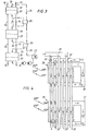
- Fig. 1 shows a fluidized bed 1, in which vertical pipes 2, 3 according to the invention for dusty, warm gas 2 or air 3, which is to be preheated, are arranged.
- Fluidizing gas here C0 2 , which circulates in a closed system 5, is introduced at the bottom 4 of the fluidization chamber.
- the fluidizing gas keeps the sand or the grains floating in the fluidizing chamber 1, as a result of which they can withstand a high temperature and prevent gas from leaking into the atmosphere.
- the temperature of the warm gas 6, which emits heat to the sand 7, and the temperature of the air 8, which absorbs heat from the sand and thus indirectly from the warm gas, are shown in the vertical direction. It is important that the lowest gas temperature (Diagram point 9) is higher than the highest air temperature (diagram point 10).
- FIG. 2 shows sand or granulate 12 as an intermediate, fluidized bed between several vertical lines for warm, dust-containing gas 11 and preheated air 13.
- the sand is expediently blown in by fluidizing gas (at 14), inert gas, such as, for. B. C0 2 , N 2 or helium, which circulates in a closed system, kept floating. (See the schematic representation according to FIG. 2a with the air 15, the warm gas 16 and the fluidizing gas 17.)
- the inlet temperature of the warm gas is 16 800 ° C and its outlet temperature is 700 ° C.
- the inlet temperature of air 15 is 550 ° C and its outlet temperature is 650 ° C.
- the sand temperature is approx. 675 ° C.
- the heat exchanger works on the principle that heat is transferred from gas to sand and from sand to air.
- the sand serves as an intermediate and prevents direct contact between gas and air in the event of a leak.
- the heat transfer between sand and pipe surfaces (11, 13 in Fig. 2) can be very high, since fine-shaped sand (for example about 0.2 mm grain diameter) can be used and the sand assumes a high temperature.
- the C0 2 stream can be adjusted to the grain size.
- the heat exchanger In order to be able to carry out a heat exchange of the warm gas and the air in countercurrent, the heat exchanger according to the invention is divided into stages (sections), as shown in FIG. 3. There are three stages in the embodiment. Warm, dusty gas 16 and air 15 are conducted in separate, vertical pipe systems through all stages 18, 19, 20, each of which contains a gas-flooded air preheater, each of which contains sand, grains or granules 21, 22 and 23, respectively, and of which each is fludged by, for example, C0 2 gas. The pressure drop in these stages does not become particularly large. The CO 2 gas (or N 2 ) used for fluidization is passed through the three stages (see FIG.
- CO 2 gas which has passed through the three stages and has reached a temperature of, for example, 675 ° C. , in heat exchangers 25, 26 in countercurrent gives off heat to upward flowing CO 2 gas.
- the downward flowing CO 2 gas has, for example, a temperature of 600 ° C. after passing through the heat exchanger 25 and a temperature of 525 ° C. after passing through the heat exchanger 26. It then passes through a water cooler in which water is heated and the gas is heated up 300 ° C is cooled. The gas is then cooled to the point where it can pass standard quality blowers.
- the inlet temperature of the warm dust-containing gas in the first stage 18 is 800 ° C
- the corresponding temperatures for stage 19 and stage 20 are 700-600 ° C and 600-500 ° C.
- C0 2 gas is passed in closed systems 30, 31 through the sand-filled fluidization chambers, and the vertical pipes for warm gas 32 and air 33 are alternately arranged adjacent; they practically interlock, which gives a good heat exchange.
- the sand, etc. prevents the CO of the warm gas from entering the air ducts.
Landscapes
- Engineering & Computer Science (AREA)
- Chemical & Material Sciences (AREA)
- Combustion & Propulsion (AREA)
- Organic Chemistry (AREA)
- General Engineering & Computer Science (AREA)
- Mechanical Engineering (AREA)
- Thermal Sciences (AREA)
- Physics & Mathematics (AREA)
- Chemical Kinetics & Catalysis (AREA)
- Manufacturing & Machinery (AREA)
- Materials Engineering (AREA)
- Metallurgy (AREA)
- Heat-Exchange Devices With Radiators And Conduit Assemblies (AREA)
- Devices And Processes Conducted In The Presence Of Fluids And Solid Particles (AREA)
- Fluidized-Bed Combustion And Resonant Combustion (AREA)
Applications Claiming Priority (2)
| Application Number | Priority Date | Filing Date | Title |
|---|---|---|---|
| SE8002101A SE420763B (sv) | 1980-03-18 | 1980-03-18 | Gasfluidiserad luftforvermare |
| SE8002101 | 1980-03-18 |
Publications (2)
| Publication Number | Publication Date |
|---|---|
| EP0036177A1 EP0036177A1 (de) | 1981-09-23 |
| EP0036177B1 true EP0036177B1 (de) | 1983-12-21 |
Family
ID=20340547
Family Applications (1)
| Application Number | Title | Priority Date | Filing Date |
|---|---|---|---|
| EP81101788A Expired EP0036177B1 (de) | 1980-03-18 | 1981-03-11 | Gasfluidisierbarer Luftvorwärmer |
Country Status (6)
| Country | Link |
|---|---|
| EP (1) | EP0036177B1 (pt) |
| JP (1) | JPS56142385A (pt) |
| BR (1) | BR8101596A (pt) |
| DE (1) | DE3161683D1 (pt) |
| SE (1) | SE420763B (pt) |
| SU (1) | SU1085517A3 (pt) |
Families Citing this family (1)
| Publication number | Priority date | Publication date | Assignee | Title |
|---|---|---|---|---|
| US6034100A (en) * | 1993-03-10 | 2000-03-07 | Otsuka Pharmaceutical Co., Ltd. | Method for inhibiting cytokine secretion |
Citations (5)
| Publication number | Priority date | Publication date | Assignee | Title |
|---|---|---|---|---|
| CH472647A (fr) * | 1967-03-13 | 1969-05-15 | Applic Electro Thermiques Soc | Procédé et appareil d'échange thermique |
| DE2746158A1 (de) * | 1977-10-14 | 1979-04-19 | Ght Hochtemperaturreak Tech | Wirbelschichtvergaser |
| US4158036A (en) * | 1977-05-02 | 1979-06-12 | Allied Chemical Corporation | Fluid bed heat recovery apparatus |
| DE2925649A1 (de) * | 1978-07-04 | 1980-01-17 | Stal Laval Apparat Ab | Waermeaustauscher zur uebertragung von waerme zwischen gasfoermigen medien |
| WO1980002193A1 (en) * | 1979-04-09 | 1980-10-16 | Norsk Viftefab As | Heat exchanger for gases |
Family Cites Families (1)
| Publication number | Priority date | Publication date | Assignee | Title |
|---|---|---|---|---|
| DD100017A5 (pt) * | 1971-11-01 | 1973-09-05 |
-
1980
- 1980-03-18 SE SE8002101A patent/SE420763B/sv unknown
-
1981
- 1981-03-11 DE DE8181101788T patent/DE3161683D1/de not_active Expired
- 1981-03-11 EP EP81101788A patent/EP0036177B1/de not_active Expired
- 1981-03-16 JP JP3775381A patent/JPS56142385A/ja active Pending
- 1981-03-17 SU SU813256348A patent/SU1085517A3/ru active
- 1981-03-18 BR BR8101596A patent/BR8101596A/pt unknown
Patent Citations (5)
| Publication number | Priority date | Publication date | Assignee | Title |
|---|---|---|---|---|
| CH472647A (fr) * | 1967-03-13 | 1969-05-15 | Applic Electro Thermiques Soc | Procédé et appareil d'échange thermique |
| US4158036A (en) * | 1977-05-02 | 1979-06-12 | Allied Chemical Corporation | Fluid bed heat recovery apparatus |
| DE2746158A1 (de) * | 1977-10-14 | 1979-04-19 | Ght Hochtemperaturreak Tech | Wirbelschichtvergaser |
| DE2925649A1 (de) * | 1978-07-04 | 1980-01-17 | Stal Laval Apparat Ab | Waermeaustauscher zur uebertragung von waerme zwischen gasfoermigen medien |
| WO1980002193A1 (en) * | 1979-04-09 | 1980-10-16 | Norsk Viftefab As | Heat exchanger for gases |
Also Published As
| Publication number | Publication date |
|---|---|
| DE3161683D1 (en) | 1984-01-26 |
| BR8101596A (pt) | 1981-09-22 |
| SE8002101L (sv) | 1981-09-19 |
| SU1085517A3 (ru) | 1984-04-07 |
| SE420763B (sv) | 1981-10-26 |
| JPS56142385A (en) | 1981-11-06 |
| EP0036177A1 (de) | 1981-09-23 |
Similar Documents
| Publication | Publication Date | Title |
|---|---|---|
| AT401418B (de) | Verfahren und vorrichtung zur steuerung der funktion eines wirbelschichtreaktors mit zirkulierender wirbelschicht | |
| DE3147864C2 (de) | Abwärmekessel für die Kühlung von Synthesegas | |
| DE602006000936T2 (de) | Zirkulierende Wirbelschichtfeuerungsanlage mit umwandelbarem Verbrennungsverfahren | |
| DE69628280T2 (de) | Wirbelbettanordnung mit durchflussausgleich | |
| DE202009005732U1 (de) | Wärmetauscher | |
| EP0036177B1 (de) | Gasfluidisierbarer Luftvorwärmer | |
| EP0036409B1 (de) | Verfahren zur Kühlung von heissen Schüttgütern | |
| DE2010601A1 (pt) | ||
| DE69107251T2 (de) | Anlage zur Vorwärmung körnigen Guts. | |
| DE4233140A1 (de) | Verfahren zur Reduktion von feinkörnigen eisenoxidhaltigen Stoffen durch Gasreduktion | |
| DE2715790A1 (de) | Schwebegasvorwaermer fuer feingut | |
| WO2012038109A2 (de) | Verfahren und anlage zur dampferzeugung | |
| DE68903187T2 (de) | Wirbelschichtkessel. | |
| DE69110640T2 (de) | Kessel mit gestütztem Wärmeübergangsbündel. | |
| DE20010671U1 (de) | Wärmetauscher für rieselfähige Feststoffe | |
| CH662405A5 (de) | Wirbelbettfeuerung. | |
| EP3441127B1 (de) | Absorptionskolonne mit aussenliegendem wärmeaustauschkreislauf | |
| DE2925649A1 (de) | Waermeaustauscher zur uebertragung von waerme zwischen gasfoermigen medien | |
| CH496628A (de) | Verfahren und Vorrichtung zur Trocknung von Abwasserschlämmen mittels eines heissen gasförmigen Mediums | |
| AT376144B (de) | Vorrichtung zum abkuehlen, entschwefeln und wiedererwaermen von rauchgasen | |
| EP0085832A2 (de) | Verfahren zur trockenen Kokskühlung und Vorrichtung zum Durchführen dieses Verfahrens | |
| DE3511877A1 (de) | Durchlaufdampferzeuger | |
| AT40675B (de) | Regenerativeinrichtung für Koksöfen. | |
| DE3343480A1 (de) | Verfahren und vorrichtung zum fluidisieren und gleichzeitigen kuehlen von wirbelschichtmaterial in einer wirbelschicht-feuerung | |
| DE4116825C2 (de) | Verbrennungseinrichtung für aschereiche Brennstoffe |
Legal Events
| Date | Code | Title | Description |
|---|---|---|---|
| PUAI | Public reference made under article 153(3) epc to a published international application that has entered the european phase |
Free format text: ORIGINAL CODE: 0009012 |
|
| AK | Designated contracting states |
Designated state(s): CH DE FR GB |
|
| 17P | Request for examination filed |
Effective date: 19820128 |
|
| GRAA | (expected) grant |
Free format text: ORIGINAL CODE: 0009210 |
|
| AK | Designated contracting states |
Designated state(s): CH DE FR GB LI |
|
| REF | Corresponds to: |
Ref document number: 3161683 Country of ref document: DE Date of ref document: 19840126 |
|
| ET | Fr: translation filed | ||
| PG25 | Lapsed in a contracting state [announced via postgrant information from national office to epo] |
Ref country code: LI Effective date: 19840331 Ref country code: CH Effective date: 19840331 |
|
| PLBE | No opposition filed within time limit |
Free format text: ORIGINAL CODE: 0009261 |
|
| STAA | Information on the status of an ep patent application or granted ep patent |
Free format text: STATUS: NO OPPOSITION FILED WITHIN TIME LIMIT |
|
| PG25 | Lapsed in a contracting state [announced via postgrant information from national office to epo] |
Ref country code: FR Free format text: LAPSE BECAUSE OF NON-PAYMENT OF DUE FEES Effective date: 19841130 |
|
| REG | Reference to a national code |
Ref country code: CH Ref legal event code: PL |
|
| PG25 | Lapsed in a contracting state [announced via postgrant information from national office to epo] |
Ref country code: DE Effective date: 19841201 |
|
| 26N | No opposition filed | ||
| REG | Reference to a national code |
Ref country code: FR Ref legal event code: ST |
|
| GBPC | Gb: european patent ceased through non-payment of renewal fee | ||
| PG25 | Lapsed in a contracting state [announced via postgrant information from national office to epo] |
Ref country code: GB Effective date: 19881118 |