EP0036201A2 - Appareil de mesure pour milieux liquides ou gazeux - Google Patents
Appareil de mesure pour milieux liquides ou gazeux Download PDFInfo
- Publication number
- EP0036201A2 EP0036201A2 EP81101906A EP81101906A EP0036201A2 EP 0036201 A2 EP0036201 A2 EP 0036201A2 EP 81101906 A EP81101906 A EP 81101906A EP 81101906 A EP81101906 A EP 81101906A EP 0036201 A2 EP0036201 A2 EP 0036201A2
- Authority
- EP
- European Patent Office
- Prior art keywords
- float
- flow meter
- housing
- flow
- damping piston
- Prior art date
- Legal status (The legal status is an assumption and is not a legal conclusion. Google has not performed a legal analysis and makes no representation as to the accuracy of the status listed.)
- Withdrawn
Links
Images
Classifications
-
- G—PHYSICS
- G01—MEASURING; TESTING
- G01F—MEASURING VOLUME, VOLUME FLOW, MASS FLOW OR LIQUID LEVEL; METERING BY VOLUME
- G01F15/00—Details of, or accessories for, apparatus of groups G01F1/00 - G01F13/00 insofar as such details or appliances are not adapted to particular types of such apparatus
- G01F15/005—Valves
-
- G—PHYSICS
- G01—MEASURING; TESTING
- G01F—MEASURING VOLUME, VOLUME FLOW, MASS FLOW OR LIQUID LEVEL; METERING BY VOLUME
- G01F1/00—Measuring the volume flow or mass flow of fluid or fluent solid material wherein the fluid passes through a meter in a continuous flow
- G01F1/05—Measuring the volume flow or mass flow of fluid or fluent solid material wherein the fluid passes through a meter in a continuous flow by using mechanical effects
- G01F1/20—Measuring the volume flow or mass flow of fluid or fluent solid material wherein the fluid passes through a meter in a continuous flow by using mechanical effects by detection of dynamic effects of the flow
- G01F1/22—Measuring the volume flow or mass flow of fluid or fluent solid material wherein the fluid passes through a meter in a continuous flow by using mechanical effects by detection of dynamic effects of the flow by variable-area meters, e.g. rotameters
- G01F1/24—Measuring the volume flow or mass flow of fluid or fluent solid material wherein the fluid passes through a meter in a continuous flow by using mechanical effects by detection of dynamic effects of the flow by variable-area meters, e.g. rotameters with magnetic or electric coupling to the indicating device
-
- G—PHYSICS
- G01—MEASURING; TESTING
- G01F—MEASURING VOLUME, VOLUME FLOW, MASS FLOW OR LIQUID LEVEL; METERING BY VOLUME
- G01F1/00—Measuring the volume flow or mass flow of fluid or fluent solid material wherein the fluid passes through a meter in a continuous flow
- G01F1/05—Measuring the volume flow or mass flow of fluid or fluent solid material wherein the fluid passes through a meter in a continuous flow by using mechanical effects
- G01F1/20—Measuring the volume flow or mass flow of fluid or fluent solid material wherein the fluid passes through a meter in a continuous flow by using mechanical effects by detection of dynamic effects of the flow
- G01F1/28—Measuring the volume flow or mass flow of fluid or fluent solid material wherein the fluid passes through a meter in a continuous flow by using mechanical effects by detection of dynamic effects of the flow by drag-force, e.g. vane type or impact flowmeter
-
- G—PHYSICS
- G01—MEASURING; TESTING
- G01F—MEASURING VOLUME, VOLUME FLOW, MASS FLOW OR LIQUID LEVEL; METERING BY VOLUME
- G01F15/00—Details of, or accessories for, apparatus of groups G01F1/00 - G01F13/00 insofar as such details or appliances are not adapted to particular types of such apparatus
- G01F15/02—Compensating or correcting for variations in pressure, density or temperature
Definitions
- the invention relates to a flow meter for liquid or gaseous media with a flow sensor arranged within a housing in the flowing medium, preferably a floating body which can be displaced under the action of the lifting force generated by the medium and which is rigidly connected via a rod to a weight body which is made of ferromagnetic material and is located in the field of a housing-fixed induction coil.
- the float which is arranged vertically in a conical tube in the flowing medium, assumes a specific position as a function of the flow rate under the action of buoyancy forces.
- the buoyancy acts counteract gravity and possibly a spring force or a sum of forces formed by both forces.
- the position of the float which is dependent on the flow rate, can be determined in a known manner by means of a stationary, that is to say housing-fixed, induction coil.
- a major advantage of this flow meter which works on the float principle, is that it can be dimensioned and calibrated when measuring liquid media in such a way that the gas contained in the liquids in the form of bubbles, unlike in measurement methods using rotors, cannot or only in a negligible manner is included in the measured value.
- a quantity meter of this type has also become known, in which both a weight and a return spring provide the counterforce. Such an arrangement is particularly sensitive to changes in the case of relatively small flow rates, such as are to be displayed in the fuel consumption of motor vehicle engines.
- the object of the present invention is to compensate for the external influences described above in such a way that the measurement errors resulting therefrom are avoided or at least reduced as far as possible.
- a damping piston which is displaceable along the connecting rod is arranged between the housing collar and the return spring, that the effective cross sections of the damping piston and floating body are approximately the same and that the media inflow opens into the housing chamber between the floating body and the damping piston.
- the damping piston proposed according to the invention is dimensioned and arranged in such a way that it is deflected to the same extent but in the opposite direction to the float under the effect of the impact or the pulsation imparted to the medium. As a result, the restoring force generated by the spring is increased in a pulse-like manner so that the float cannot follow the impact communicated to it.
- the return spring which is preferably designed as a helical spring, is dimensioned in such a way that it presses the damping piston in the initial position of the float against the stop fixed to the housing, that is to say carries it.
- the float is deflected due to an increase in the flow rate, the change in movement is counteracted by the inertial mass of the entire float system, consisting of the float, connecting rod and counterweight, and the spring force. If, on the other hand, the system experiences a shock, the inertial mass counteracting the movement of the float is increased by the mass formed by the damping piston. This measure leads to stabilization of the float for the following reason.
- the use of the return spring leads to the largely independent positional functioning of the flow meter. Even in the horizontal position, the spring generates a restoring force that counteracts the buoyancy force. With this spring, the float system located in the flowing medium can also be centered, namely when, as is also proposed, the weight body and the damping piston, between which the spring is clamped, have this position-fixing and centering receptacle.
- This proposal is realized in a simple manner in that the damping piston and the weight body are pot-shaped on their side facing the spring.
- the position centering of the system also serves a further proposal according to the invention, according to which the housing collar sits a receptacle centering the damping piston in the rest position, the openings of the receptacle and the damping piston, through which the connecting rod between the float and weight body are passed, larger than the rod diameter must be so that contact between the connecting rod and the collar or the damping piston and thus friction losses are avoided.
- the float itself is centered in a rotationally symmetrical design by the medium flowing around it.
- the effective part of the float has hitherto been designed either in the form of a circular plate or in the form of a truncated cone with a cross section increasing in the direction of flow.
- the float is designed in the form of a cone, the base surface of which forms the baffle plate is located at the front in the direction of flow and which tapers in the direction of flow. With this measure, the tip vortex generated at the edge of the float solve quickly from Schwebekör he p from.
- a further stabilizing effect is achieved if the conical float has a cylinder disk-shaped baffle plate on the side facing the flow.
- This cylindrical disc results on the one hand in a viscosity independence in the initial measuring range and on the other hand a display stability in the final measuring range.
- a further stabilization can finally be achieved in that the above-described conical float has a cylinder provided on the connecting rod on its front side in the direction of flow, the length of which is substantially greater than its diameter.
- the damping piston arrangement explained above is very well suited to compensating for the measurement errors caused by the vehicle movement.
- a valve plate As a pressure control valve in a flow meter with a float, a valve plate is suitable, which acts against the flow by means of a coil spring acting against the flow Downstream side of the housing provided valve seat is pressed.
- Another problem is the fine tuning and linearization of the sensor in manufacturing or assembly.
- an adjusting body which can be changed in position is provided, which influences the magnetic field within the induction coil in the region of the weight body immersed in the coil.
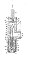
- the drawing shows an axial section through a flow meter designed according to the invention.
- the flow meter J shown in the drawing consists of a housing 11, in which the medium to be measured in a device of the construction shown and the dimensions specified, a liquid fuel, preferably gasoline, via the inlet 12, the chamber 13 into the cone 14 serving for the measurement and is led to the outlet 15.
- the float is displaceable relative to the measuring section provided, which consists of an elongated cylindrical extension 8, a flat cylindrical disk-shaped baffle plate 9 and a cone 10 tapering in the direction of flow.
- This float 8, 9, 10 is connected via a rod 7 to the weight body 2, which is located in the lower cylindrical part 16 of the housing and is also flowed around by the medium.
- the lower end of the housing is closed by a screw 1 which seals by means of an O-ring 23.
- the weight body 2 provides the counterforce against the buoyancy force acting on the weight body 8, 9, 10. This counterforce is further supported by the restoring force of the coil spring 4, which is clamped between the counterweight 2 and the damping piston 5, which in turn rests on an annular collar 6 fixed to the housing.
- the collar 6 has on its side facing the damping piston 5 a receptacle 6a with which the damping piston 5 is centered in the rest position.
- the coil spring 4 in turn is supported and centered on the one hand by means of the receptacle 5a of the damping piston 5 and on the other hand the receptacle 2a of the weight body 2. This arrangement of the spring 4 within the cavities 2a and 5a leads to a not insignificant reduction in the longitudinal dimension of the device.
- the entire structure with the components 2 and 7 to 10 maintains its central position with only slight deviations even with inclinations of the housing 11.
- the openings 5b in the damping piston 5 and 6b in the collar 6 are dimensioned significantly larger than the cross section of the connecting rod 7.
- the weight body 2 is made of ferromagnetic material and forms a displaceable core within the induction coil 3 fixed to the housing.
- the change in inductance due to the displacement of the weight body 2 represents a measure of the buoyancy forces acting on the float 8, 9, 10 and thus for the flow rate.
- the change in inductance is measured using circuits known per se, for example by means of an AC-powered measuring bridge, in one branch the induction coil 3 is arranged.
- Deviations occurring in the electrical measuring circuit can be compensated for with an adjusting screw 17 made of magnetic material, which can be screwed more or less into the magnetic inner field of the induction coil 3.
- the adjusting screw 17 is inserted into the screw plug.
- the induction coil 3 which is based on a tapered approach made of non-ferromagnetic material, e.g. Brass, VA steel or aluminum, existing housing 11 is wound or pushed on, covered by a metal shielding tube.
- a metal shielding tube To secure the position, the outer annular space 22 between the attachment of the housing 11, the induction coil 3 and the shielding tube 24 is filled with an electrically insulating casting compound.
- An essential element according to the present invention is the damping piston 5, the mode of operation of which has already been explained in detail in the introduction to the description.
- the float 8, 9, 10 experiences an additional force in the direction of flow, so that the displacement of the float caused thereby simulates a higher flow.
- a force acts in the opposite direction on the damping piston, the cross section of which corresponds approximately to the cross section of the float, this is also deflected, as a result of which the restoring force of the spring 4, which is now more preloaded, is increased. This increase in the restoring force compensates for the shock-related increase in the buoyancy force acting on the float.
- the damping piston together with the float section 10 which is conical according to the present invention, compensates for eddy forces which act on the float and which occur as a result of impacts transmitted to the housing 11.
- the pressure holding valve serves to prevent measurement errors which are the result of abrupt changes in the flow rate.
- This pressure maintaining valve is located in the flow path behind the conical measuring section 14, within which the float 10 is displaceably located. and in front of the outlet side 15.
- it consists of a valve plate 19 which, under the action of the coil spring 20, is pressed against the conical valve seat 21 on the outlet side of the housing 11.
- the spring 20 is supported against the inside of the connection piece 18 screwed to the housing end.
- the conical valve seat effects a symmetrical pressure distribution for centering the valve plate 19, which is also provided with a conical outer surface.
- the valve plate 19 Under the action of the flow pressure, which entrains the float 10, the valve plate 19 is also raised against the force of the spring 20. Is abruptly on the outlet side, e.g. when accelerating, more liquid is sucked off, in the absence of the pressure control valve, the float 10 would be sucked in and its position would apparently indicate a larger flow rate than the actual instantaneous flow rate. In order to prevent this false indication or at least to reduce the measurement error, the pressure-maintaining valve is provided between the float 10 and the outlet connection 18; causes.
- the valve operates in the event of a sudden drop in the liquid removed on the discharge side, which leads to a brief overpressure.
- This overpressure shifts the valve plate 19 against the direction of flow and prevents the restoring force arising from the overpressure from being transmitted to the float 10, which would likewise lead to a falsification of the measured values.
- the pressure control valve which can also be referred to as a damping valve, is particularly simple to implement in a flow meter of the type described, as the drawing clearly shows.
Landscapes
- Physics & Mathematics (AREA)
- Fluid Mechanics (AREA)
- General Physics & Mathematics (AREA)
- Measuring Volume Flow (AREA)
Applications Claiming Priority (4)
| Application Number | Priority Date | Filing Date | Title |
|---|---|---|---|
| DE19803010282 DE3010282C2 (de) | 1980-03-18 | 1980-03-18 | Schwebekörperdurchflußmesser für flüssige und gasförmige Medien |
| DE3010282 | 1980-03-18 | ||
| DE3040320 | 1980-10-25 | ||
| DE3040320 | 1980-10-25 |
Publications (2)
| Publication Number | Publication Date |
|---|---|
| EP0036201A2 true EP0036201A2 (fr) | 1981-09-23 |
| EP0036201A3 EP0036201A3 (fr) | 1984-05-16 |
Family
ID=25784374
Family Applications (1)
| Application Number | Title | Priority Date | Filing Date |
|---|---|---|---|
| EP81101906A Withdrawn EP0036201A3 (fr) | 1980-03-18 | 1981-03-14 | Appareil de mesure pour milieux liquides ou gazeux |
Country Status (2)
| Country | Link |
|---|---|
| US (1) | US4368646A (fr) |
| EP (1) | EP0036201A3 (fr) |
Families Citing this family (21)
| Publication number | Priority date | Publication date | Assignee | Title |
|---|---|---|---|---|
| US4424716A (en) | 1981-06-15 | 1984-01-10 | Mcdonnell Douglas Corp. | Hydraulic flowmeter |
| GB8305926D0 (en) * | 1983-03-03 | 1983-04-07 | Fluid Devices Ltd | Fluid flow sensors |
| US4739650A (en) * | 1985-11-19 | 1988-04-26 | Nippondenso Co., Ltd. | Gas flow measuring apparatus |
| US4993269A (en) * | 1988-12-16 | 1991-02-19 | Bird Products Corporation | Variable orifice flow sensing apparatus |
| DE69533597T2 (de) * | 1994-10-14 | 2005-10-06 | Bird Products Corporation, Palm Springs | Ausatmungsventil mit Messwertaufnehmer für die Ausatmungsströmung |
| US5717137A (en) * | 1996-02-01 | 1998-02-10 | Standex International Corporation | Flow monitoring line strainer |
| JP2001502776A (ja) * | 1996-10-09 | 2001-02-27 | ジー.ティー.プロダクツ,インコーポレイテッド | フロートバルブの調整装置および方法 |
| US6135967A (en) * | 1999-04-26 | 2000-10-24 | Fiorenza; Anthony Joseph | Respiratory ventilator with automatic flow calibration |
| US6240919B1 (en) | 1999-06-07 | 2001-06-05 | Macdonald John J. | Method for providing respiratory airway support pressure |
| US6339959B1 (en) | 2000-05-10 | 2002-01-22 | N.M.F. Ltd. | Magnetic float type flowmeter |
| US6374846B1 (en) | 2001-01-19 | 2002-04-23 | Flologic, Inc. | System for excercising the control valve for a water shut-off valve |
| AT410979B (de) * | 2002-02-01 | 2003-09-25 | Raimund Janaczek | Durchflussmengenmesser für verteilerventil |
| US20050221087A1 (en) * | 2004-02-13 | 2005-10-06 | James Economy | Nanoporous chelating fibers |
| US20070252008A1 (en) * | 2006-04-27 | 2007-11-01 | Rowe James C | Position indicator using a moveable sensor and a light path viewed |
| DE102012021363B4 (de) | 2012-11-02 | 2016-08-11 | Krohne Messtechnik Gmbh | Vorrichtung zur Bestimmung des Durchflusses nach dem Schwebekörperprinzip |
| WO2018013857A1 (fr) | 2016-07-13 | 2018-01-18 | Rain Bird Corporation | Capteur d'écoulement |
| US10704935B2 (en) * | 2016-12-04 | 2020-07-07 | Buoy Labs, Inc. | Fluid flow detector with tethered drag block |
| US10473494B2 (en) | 2017-10-24 | 2019-11-12 | Rain Bird Corporation | Flow sensor |
| US11662242B2 (en) | 2018-12-31 | 2023-05-30 | Rain Bird Corporation | Flow sensor gauge |
| US12443208B2 (en) | 2023-02-08 | 2025-10-14 | Rain Bird Corporation | Control zone devices, systems and methods |
| US12498049B2 (en) | 2024-03-29 | 2025-12-16 | Rain Bird Corporation | Zone control devices, systems and methods |
Family Cites Families (14)
| Publication number | Priority date | Publication date | Assignee | Title |
|---|---|---|---|---|
| GB168042A (en) * | 1921-07-06 | 1922-08-10 | Hoechst Ag | Improvements in fluid flow meters |
| DE378726C (de) * | 1922-03-24 | 1923-07-30 | Richard Bosselmann | Vorrichtung zur Messung der Durchflussmenge von stroemenden Fluessigkeiten und Gasenmit einem in einem verengten Durchflussrohr beweglichen Messkoerper |
| GB197195A (en) * | 1922-05-12 | 1923-05-10 | Ernst Claassen | Improvements in or relating to fluid meters |
| US2647402A (en) * | 1946-05-16 | 1953-08-04 | Negretti & Zambra Ltd | Flow metering mechanism |
| US2640356A (en) * | 1950-04-22 | 1953-06-02 | Bailey Meter Co | Variable orifice flowmeter |
| BE526267A (fr) * | 1953-02-11 | |||
| US2800019A (en) * | 1953-06-11 | 1957-07-23 | Exxon Research Engineering Co | Density compensating flowmeter |
| US3133441A (en) * | 1960-09-13 | 1964-05-19 | Wallace & Tiernan Inc | Stabilizing device for variable restriction fluid flow meters |
| US3287971A (en) * | 1964-06-10 | 1966-11-29 | Weatherhead Co | Flowmeter |
| FR1431867A (fr) * | 1965-02-03 | 1966-03-18 | Perfectionnements apportés aux indicateurs de débit | |
| DE1601612A1 (de) * | 1967-06-10 | 1970-12-17 | Motoren Turbinen Union | Differenzdruckregler einer Brennstoffregelvorrichtung,insbes? fuer Gasturbinenstrahltriebwerke |
| US3931737A (en) * | 1974-07-12 | 1976-01-13 | Pennwalt Corporation | Pulsating liquid flow transmitter |
| DE2722239B2 (de) * | 1977-05-17 | 1980-12-18 | G.L. Rexroth Gmbh, 8770 Lohr | Durchflußmeßgerät |
| US4304136A (en) * | 1980-02-01 | 1981-12-08 | Transamerica Delaval Inc. | Electrical transducer responsive to fluid flow |
-
1981
- 1981-03-09 US US06/241,717 patent/US4368646A/en not_active Expired - Fee Related
- 1981-03-14 EP EP81101906A patent/EP0036201A3/fr not_active Withdrawn
Also Published As
| Publication number | Publication date |
|---|---|
| US4368646A (en) | 1983-01-18 |
| EP0036201A3 (fr) | 1984-05-16 |
Similar Documents
| Publication | Publication Date | Title |
|---|---|---|
| DE69014911T2 (de) | Füllstandsensor für Fluide. | |
| DE2615009C2 (de) | Antrieb für einen Durchflußregelhahn | |
| EP0036201A3 (fr) | Appareil de mesure pour milieux liquides ou gazeux | |
| DE2946826A1 (de) | Durchflusswaechter fuer fluessige oder gasfoermige medien | |
| EP1881316A2 (fr) | Méthode et dispositif pour déterminer la densité d'un fluide | |
| DE3120725A1 (de) | "druckmessgeraet" | |
| DE2351940C3 (de) | Druckmeßsonde | |
| GB1591690A (en) | Flowmeters | |
| DE3112960C2 (de) | Meßturbine C | |
| DE2501380A1 (de) | Messgeraet zur ermittlung der menge pro zeiteinheit eines stroemenden mediums | |
| DE3010282C2 (de) | Schwebekörperdurchflußmesser für flüssige und gasförmige Medien | |
| DE1148771B (de) | Gas- und Fluessigkeitsmengenmesser mit veraenderlicher Blende | |
| DE19639060C2 (de) | Schwebekörper-Durchflußmesser | |
| EP0301258B1 (fr) | Procédé pour mesurer le débit des fluides | |
| DE3940474C1 (fr) | ||
| DE3906432C2 (de) | Turbinenzähler | |
| DE1212310B (de) | Stroemungsmessgeraet | |
| DE2635744A1 (de) | Durchflussmesser | |
| EP0949484A1 (fr) | Débimètre | |
| DE2923203A1 (de) | Durchflussmengenmesser fuer fluessige und gasfoermige medien | |
| DE1798183C2 (de) | Flüssigkeitsdurchlaufanzeigegerät | |
| DE3426361A1 (de) | Durchflussmesser | |
| DE2509447A1 (de) | Messwertgeber zur messung der durchflussgeschwindigkeit von fluessigkeiten | |
| EP0505958B1 (fr) | Débitmètre | |
| DE2110688A1 (de) | Durchflussmesseinrichtung fuer fluessige und gasfoermige Medien |
Legal Events
| Date | Code | Title | Description |
|---|---|---|---|
| PUAI | Public reference made under article 153(3) epc to a published international application that has entered the european phase |
Free format text: ORIGINAL CODE: 0009012 |
|
| AK | Designated contracting states |
Designated state(s): AT BE CH DE FR GB IT LI LU NL SE |
|
| PUAL | Search report despatched |
Free format text: ORIGINAL CODE: 0009013 |
|
| RHK1 | Main classification (correction) |
Ipc: G01F 1/26 |
|
| AK | Designated contracting states |
Designated state(s): AT BE CH DE FR GB IT LI LU NL SE |
|
| STAA | Information on the status of an ep patent application or granted ep patent |
Free format text: STATUS: THE APPLICATION IS DEEMED TO BE WITHDRAWN |
|
| 18D | Application deemed to be withdrawn |
Effective date: 19850117 |
|
| RIN1 | Information on inventor provided before grant (corrected) |
Inventor name: ROGG, WERNER, DIPL.-PHYS. |