EP0036242A2 - Pièges de lumière à fibres optiques pour des dispositifs d'affichage électro-optiques - Google Patents
Pièges de lumière à fibres optiques pour des dispositifs d'affichage électro-optiques Download PDFInfo
- Publication number
- EP0036242A2 EP0036242A2 EP81300233A EP81300233A EP0036242A2 EP 0036242 A2 EP0036242 A2 EP 0036242A2 EP 81300233 A EP81300233 A EP 81300233A EP 81300233 A EP81300233 A EP 81300233A EP 0036242 A2 EP0036242 A2 EP 0036242A2
- Authority
- EP
- European Patent Office
- Prior art keywords
- faceplate
- display
- light
- angle
- electro
- Prior art date
- Legal status (The legal status is an assumption and is not a legal conclusion. Google has not performed a legal analysis and makes no representation as to the accuracy of the status listed.)
- Granted
Links
Images


Classifications
-
- G—PHYSICS
- G02—OPTICS
- G02F—OPTICAL DEVICES OR ARRANGEMENTS FOR THE CONTROL OF LIGHT BY MODIFICATION OF THE OPTICAL PROPERTIES OF THE MEDIA OF THE ELEMENTS INVOLVED THEREIN; NON-LINEAR OPTICS; FREQUENCY-CHANGING OF LIGHT; OPTICAL LOGIC ELEMENTS; OPTICAL ANALOGUE/DIGITAL CONVERTERS
- G02F1/00—Devices or arrangements for the control of the intensity, colour, phase, polarisation or direction of light arriving from an independent light source, e.g. switching, gating or modulating; Non-linear optics
- G02F1/01—Devices or arrangements for the control of the intensity, colour, phase, polarisation or direction of light arriving from an independent light source, e.g. switching, gating or modulating; Non-linear optics for the control of the intensity, phase, polarisation or colour
- G02F1/13—Devices or arrangements for the control of the intensity, colour, phase, polarisation or direction of light arriving from an independent light source, e.g. switching, gating or modulating; Non-linear optics for the control of the intensity, phase, polarisation or colour based on liquid crystals, e.g. single liquid crystal display cells
- G02F1/133—Constructional arrangements; Operation of liquid crystal cells; Circuit arrangements
- G02F1/1333—Constructional arrangements; Manufacturing methods
- G02F1/1335—Structural association of cells with optical devices, e.g. polarisers or reflectors
- G02F1/133524—Light-guides, e.g. fibre-optic bundles, louvered or jalousie light-guides
-
- G—PHYSICS
- G02—OPTICS
- G02B—OPTICAL ELEMENTS, SYSTEMS OR APPARATUS
- G02B6/00—Light guides; Structural details of arrangements comprising light guides and other optical elements, e.g. couplings
- G02B6/04—Light guides; Structural details of arrangements comprising light guides and other optical elements, e.g. couplings formed by bundles of fibres
- G02B6/06—Light guides; Structural details of arrangements comprising light guides and other optical elements, e.g. couplings formed by bundles of fibres the relative position of the fibres being the same at both ends, e.g. for transporting images
- G02B6/08—Light guides; Structural details of arrangements comprising light guides and other optical elements, e.g. couplings formed by bundles of fibres the relative position of the fibres being the same at both ends, e.g. for transporting images with fibre bundle in form of plate
-
- G—PHYSICS
- G02—OPTICS
- G02F—OPTICAL DEVICES OR ARRANGEMENTS FOR THE CONTROL OF LIGHT BY MODIFICATION OF THE OPTICAL PROPERTIES OF THE MEDIA OF THE ELEMENTS INVOLVED THEREIN; NON-LINEAR OPTICS; FREQUENCY-CHANGING OF LIGHT; OPTICAL LOGIC ELEMENTS; OPTICAL ANALOGUE/DIGITAL CONVERTERS
- G02F1/00—Devices or arrangements for the control of the intensity, colour, phase, polarisation or direction of light arriving from an independent light source, e.g. switching, gating or modulating; Non-linear optics
- G02F1/01—Devices or arrangements for the control of the intensity, colour, phase, polarisation or direction of light arriving from an independent light source, e.g. switching, gating or modulating; Non-linear optics for the control of the intensity, phase, polarisation or colour
- G02F1/13—Devices or arrangements for the control of the intensity, colour, phase, polarisation or direction of light arriving from an independent light source, e.g. switching, gating or modulating; Non-linear optics for the control of the intensity, phase, polarisation or colour based on liquid crystals, e.g. single liquid crystal display cells
- G02F1/133—Constructional arrangements; Operation of liquid crystal cells; Circuit arrangements
- G02F1/135—Liquid crystal cells structurally associated with a photoconducting or a ferro-electric layer, the properties of which can be optically or electrically varied
Definitions
- This invention relates generally to electro-optical display devices wherein information is displayed on a surface and particularly to such devices which achieve high contrast by using a fiber optic faceplate as a light trap.
- Electro-optical display panels wherein information such as images or alphanumeric characters is displayed on a surface includes both active and passive devices.
- Active devices such as light emitting diodes, gas discharge elements, and thin film electro-luminescent elements generate their own light.
- Passive devices such as liquid crystal displays generate no light of their own but rather modulate incident light from natural or artificial external sources.
- liquid crystal display with which this invention is concerned is a liquid crystal in which the basic components include a liquid crystal layer sandwiched between a transparent front electrode and a reflective back electrode. In the off-state, that is with no voltage applied across the electrodes, the liquid crystal is transparent. Conversely, in the on-state, that is with a voltage applied across the electrodes, current flowing through the liquid crystal creates a turbulence that causes scattering of the light passing through the layer so that the liquid crystal appears like frosted glass. By proper illumination techniques, the viewer can distinguish between the scattering and nonscattering regions. Because the . scattering increases with applied voltage, shades of grey may be obtained by varying the voltage applied to various elements. This mode of modulation of the transmissivity of liquid crystal material in response to an applied voltage is called the "dynamic scattering mode".
- a spatially modulated. electric field pattern containing image information to be displayed is impressed upon the liquid crystal by one of several methods.
- a matrix of individually addressable minute electrodes, each electrode forming one picture element is formed on the backplate of the liquid crystal light valve.
- the image containing electric field pattern is generated from an input image directed onto a photo-conductive layer located on the backside of the liquid crystal light device.
- a photo-conductive layer located on the backside of the liquid crystal light device.
- the display surface is tilted to -the viewers line of sight so that when the liquid crystal is in the transparent off-state, the viewer sees the dark light trap surface reflected from the backplate of the liquid crystal device with the result that the light valve appears black.
- the illumination is scattered from it toward the observer so that the activated portion of the surface appears white.
- this display arrangement maintains a high contrast image even under illumination from highly intense sources, the arrangement has several disadvantages, one of them being that the tilt of the display surface causes objectionable foreshortening of the image displayed on the liquid crystal layer.
- Another disadvantage is the difficulty in designing a light trap geometry which permits locating an artificial light source needed to illuminate the display without blocking the field of view.
- an object of the present invention to provide means for improving the performance of image display arrangements using either active or passive electro-optical display devices.
- Another object of the present invention is to provide a display device which blocks all specular reflections from the display surface so as to maintain a high-contrast image.
- a further object of the invention is to provide a direct view electro-optical display device which is compact.
- a still further object is to provide such a display device which can be viewed perpendicularly to the display surface, thereby decreasing geometric distortion present in the prior art devices of this type.
- Yet another object is to provide a liquid crystal display device in which an external light source can be conveniently located near the plane of the display so as to leave the field of view unobstructed.
- an image display device in which an electro-optical display panel having a specularly reflecting surface is optically coupled to a fiber optic faceplate.
- the faceplate has a back surface adjacent the display surface and a front surface which is aligned at a predetermined angle ⁇ to the back surface.
- the faceplate comprises a multiplicity of parallel optical fiber, each of which have an acceptance solid angle which defines exclusively the angular range through which light is,transmitted through the fibers.
- the fiber axes are tilted at an.angle to the back surface such that light which enters the front surface of the faceplate and is specularly reflected from the display surface is trapped within the faceplate.
- light emitted or scattered from on-state display elements is transmitted through the faceplate to the viewer.
- a high contrast display results because reflecting off-state elements on the display surface appear dark under even high ambient light levels whereas the scattering or emitting on-state elements appear bright.
- the size and the direction of the display field of view is controlled by selecting the proper value of angle a .
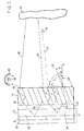
- the electro-optical display panel 10 is a liquid crystal device operating in the dynamic scattering mode. It is formed by sandwiching a layer of liquid crystal material 12 between a reflective electrode 18 mounted upon backplate 20 and a fiber optic faceplate 14 having a front major surface 24 and a back major surface 26. Surfaces 24 and 26 are parallel to liquid crystal layer 12:
- the inner surface of faceplate 14 has a transparent electrode 22.
- liquid crystal layer 12 is transparent when no electric field is present but scatters light when an electric field is applied. If the electric field is driven by electronic signals, then the backplate 20 contains a matrix array of reflective electrodes as described earlier.
- backplate 20 includes a photoconductor of the type shown in-the Beard or Fraas patents described above. With either of these drive, arrangements, the image desired for display is transformed.into an electric field pattern across the liquid crystal layer.
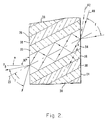
- FIG. 2 illustrating in greater detail one type of fiber optic faceplate 14 suitable for use with the system of FIG. 1.
- the faceplate is formed by a multiplicity of optical fibers whose longitudinal axes, such as axis 23, are parallel to each other and slanted at an angle a to the perpendicular P B to.back surface 26.
- angle a will be amplified later.
- Each fiber comprises a transparent core 34 covered with a transparent sheath 36 having an index of refraction less than the index of refraction of core 34 and the sheath is, in turn, covered by an optically absorbing material 38 which can form either a layer on sheath 36 or an interstitial filler between adjacent fibers formed by core 34 and sheath 36.
- Light such as ray 40, incident within a solid angle which subtends an angle F to be defined, propagates through the core 34 by means of multiple total internal reflections from the boundary of the core 34 and transparent sheath 36.
- light outside the acceptance angle does not transmit through the fiber.
- a highly oblique array such as ray 42 incident on the faceplate outside of angle F will not be totally reflected but will instead propagate through the sheath 36 and be absorbed in the light absorbing layer 38.
- the faceplate thus has a light acceptance solid angle which defines exclusively the angular range through which light is transmitted through the faceplate.
- Suitable all-glass fiber optic faceplate material having a wide range of indices of refraction is available as a standard product known as fused fiber faceplate containing ExtraMural Absorption (EMA), where EMA refers to the light absorbing material 38.
- EMA ExtraMural Absorption
- Vendors of the product include Gallileo Electro-Optics Corp., Sturbridge, Massachusetts; American Optical Company Corp., Sturbridge, Massachusetts and Collimated Holes, Inc., Cambell, California.
- the faceplate can have a more complex structure than described with reference to FIG. 2, but all have an array of fibers comprising a light transmitting core 34 and a light absorbing material which in combination provide a well defined solid angle having a specified elevation angle F. From a block of the EMA material, the faceplate 14 is cut and polished by conventional optical fabrication techniques into a plate having parallel faces at an angle a to the optical fiber axes.
- source 56 can be, for example, bright sky, illuminated room walls or other natural or artifical light sources.
- ray 46 incident upon a liquid crystal area 50 in the off-state is specularly reflected from electrodes 18 along ray path 52 back into the faceplate 14 where it is absorbed.
- the fiber slant angle a to back surface 26 is selected such that all light which enters the front surface 24 of faceplate 14 and is specularly reflected from electrode 18 is directed outside of the acceptance solid angle F and is therefor trapped by absorption within faceplate 14. The result is that the on-state region 50 appears dark.
- n 2 The nominal sheath index of refraction n 2 is increased to n' 2 by the proximity of the EMA material 38. Values of n l , n 2 and n 1 2 for various faceplate materials are available from the vendors previously given.
- the inequality sign in equation (1) represents the fact that in practice, a is increased by a few degrees to compensate for manufacturing tolerances in the faceplate 14 and electro-optical display device 10.
- Angle F is related to the indices of refraction of the core and the sheath, n 1 and n 2 , respectively, and the slant angle a by the relationship:
- the geometric foreshortening present in the prior art display using a planar light trap described earlier is minimized.
- the compactness of the device makes it suitable for use in cramped areas such as aircraft cockpits and automobile dashboards.
- FIG. 1 The cause of this field of view limitation is illustrated in FIG. 1. Rays such as ray 59 leaving the display surface at angles near the faceplate perpendicular P B are trapped within the faceplate by total internal reflection at front surface 24.
- an external light source 60 is located in front and near the plane of faceplate 14 but within the acceptance angle-F as shown in FIG. 1. Thus positioned, the source does not interfere with the viewer's line of sight. Light from source 60 is collected by a mirror 62 and directed onto the front surface 24 of faceplate 14 so that the light will exit the back surface 26 of the faceplate in order to illuminate the liquid crystal layer 12. Light source 60 can be an arc lamp, incandescent light or a fluorescent tube.
- FIG. 3 A further embodiment of the invention is illustrated . in FIG. 3.
- the electro-optical display panel 10 comprises light emitting elements such as elements 64 and 65 which, in addition to emitting light, also undesirably reflect ambient illumination.
- These elements can be gas discharge, light emitting diodes or thin film electro-luminescent devices, to name some specific examples.
- the faceplate 14 provides the display with a high contrast over a wide viewing angle even when viewed in high intensity ambient illumination.
- unwanted light source 66 emits a light ray 68 which is specularly reflected from element 64 in the off-state. All specularly reflected light is absorbed by the face plate so that the display appears dark.
- .emitting element 65 emits diffusely in all directions. ' Much of the emitted light is within the acceptance angles of the faceplate and some, such as ray 69, is thereby transmitted to the viewer 70. Thus, the off elements of .the display appear dark and the on elements appear bright, even under intense eaternal illumination condztions.
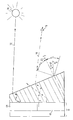
- FIG. 4 A third embodiment of the present invention is illstrated in FIG. 4.
- the embodiment of FIG. 4 is the same as that of FIG. 1 except that the fiber optic face plate 14 is modified into a wedge shape in which the back surface 26 remains parallel to the liquid crystal display layer 12 and the front surface 24 is tilted in elevation at an angle ⁇ to the back surface of the face plate.
- the advantage of a faceplate of the wedge shape shown in FIG. 4 is that the field of view is tilted towards the normal relative .to the faceplate configuration of FIG. 1. Therefore, the display can be viewed perpendicularly to the front surface 24 of the faceplate.
- the field of view is somewhat limited because some light is undesireably trapped within the faceplate by total internal reflection at the interface between the front surface 24 and air. This limitation is minimized, if not eliminated, by wedging the faceplate as shown in F IG . 4. With the wedge.angle properly selected, all light can be made to exit the faceplate.
- the beneficial results are that the display has a maximum possible field of view and, by proper design, the field of view can be tilted so as to be centered about the perpendicular to the front surface 24.
- the wedge angle ⁇ required to maximize field of view, 'while maintaining the upper edge of the field of view near the surface 24 to allow external illumination as previously shown in FIG. 1, is given by the relationship
- angle ⁇ lies within the plane of the drawing; that is, a plane passing through perpendicular P B and Pp
- the field of view in elevation can be defined by V , the sum of angles F H and F L , lying respec t-ively above and below the perpendicular P F .
- V 110.7°
- a light source 60 and mirror 62 can be located as shown at the top of the display at the edge of the viewing cone in order to provide fill- in and night illumination.
- FIG. 5 there is shown a light emitting display device as another embodiment of the invention.
- Light such as ray 72 from unwanted source 74 is transmitted by total internal reflection to the face plate 14, reflected off the specular surface of active element 64 and trapped within the face plate as shown.
- some of the light emitted by element 65 in the on state is directed back along path 76 to the viewer 78.
- the beneficial effects common to all display embodiments shown is that a high contrast is provided over a wide viewing angle even under intense illumination, while using a compact light trap.
- the field of view need not extend to the edge of the display.
- the value of ⁇ is selected so as to have a field of view centered on the perpendicular P F of the front surface 24 of the faceplate.
- Such a field of view can be achieved by selecting wedge angle 6 such that the axis of the fibers 23 is perpendicular to the front surface 24.
Landscapes
- Physics & Mathematics (AREA)
- Nonlinear Science (AREA)
- General Physics & Mathematics (AREA)
- Optics & Photonics (AREA)
- Mathematical Physics (AREA)
- Chemical & Material Sciences (AREA)
- Crystallography & Structural Chemistry (AREA)
- Devices For Indicating Variable Information By Combining Individual Elements (AREA)
- Liquid Crystal (AREA)
- Light Guides In General And Applications Therefor (AREA)
Applications Claiming Priority (2)
| Application Number | Priority Date | Filing Date | Title |
|---|---|---|---|
| US130638 | 1980-03-17 | ||
| US06/130,638 US4344668A (en) | 1980-03-17 | 1980-03-17 | Fiber optic light traps for electro-optical display devices |
Publications (3)
| Publication Number | Publication Date |
|---|---|
| EP0036242A2 true EP0036242A2 (fr) | 1981-09-23 |
| EP0036242A3 EP0036242A3 (en) | 1981-10-07 |
| EP0036242B1 EP0036242B1 (fr) | 1987-10-28 |
Family
ID=22445628
Family Applications (1)
| Application Number | Title | Priority Date | Filing Date |
|---|---|---|---|
| EP81300233A Expired EP0036242B1 (fr) | 1980-03-17 | 1981-01-20 | Pièges de lumière à fibres optiques pour des dispositifs d'affichage électro-optiques |
Country Status (6)
| Country | Link |
|---|---|
| US (1) | US4344668A (fr) |
| EP (1) | EP0036242B1 (fr) |
| JP (1) | JPS56130721A (fr) |
| AU (1) | AU534281B2 (fr) |
| DE (1) | DE3176500D1 (fr) |
| IL (1) | IL61843A (fr) |
Cited By (2)
| Publication number | Priority date | Publication date | Assignee | Title |
|---|---|---|---|---|
| EP0620471A1 (fr) * | 1993-04-13 | 1994-10-19 | Hewlett-Packard Company | Plaque frontale à fibres optiques inclinées |
| US9772446B2 (en) | 2014-03-14 | 2017-09-26 | Bae Systems Plc | Displays |
Families Citing this family (30)
| Publication number | Priority date | Publication date | Assignee | Title |
|---|---|---|---|---|
| US4946238A (en) * | 1984-01-27 | 1990-08-07 | University Of Pittsburgh | Fiber optic coupler |
| US4669813A (en) * | 1984-08-01 | 1987-06-02 | Incom, Inc. | Faceplate incorporating an off-axis filter |
| JPS6462155A (en) * | 1987-08-31 | 1989-03-08 | Tadashi Ijima | Exothermic body |
| US5181130A (en) * | 1990-01-09 | 1993-01-19 | Hewlett-Packard Company | Fiber optic faceplate liquid crystal display |
| US5035490A (en) * | 1990-01-09 | 1991-07-30 | Hewlett-Packard Company | Fiber optic |
| US5089941A (en) * | 1990-09-06 | 1992-02-18 | The United States Of America As Represented By The Secretary Of The Navy | Flux containment device |
| US5131065A (en) * | 1991-03-06 | 1992-07-14 | The Boeing Company | High luminance and contrast flat display panel |
| US5442467A (en) * | 1994-03-21 | 1995-08-15 | Xerox Corporation | Enhanced off-axis viewing performance and luminous efficiency of a liquid crystal display employing fiberoptic faceplate elements |
| US5812186A (en) * | 1994-07-25 | 1998-09-22 | Polaroid Corporation | Three-dimensional display method(s) and apparatus |
| JPH095745A (ja) * | 1995-06-07 | 1997-01-10 | Xerox Corp | カラー液晶ディスプレイ装置の光ファイバフェースプレート |
| US6005692A (en) * | 1997-05-29 | 1999-12-21 | Stahl; Thomas D. | Light-emitting diode constructions |
| US6487350B1 (en) * | 1998-07-16 | 2002-11-26 | Brookhaven Science Associates | Multi-clad black display panel |
| US6301417B1 (en) | 1998-08-31 | 2001-10-09 | Brookhaven Science Associates | Ultrathin optical panel and a method of making an ultrathin optical panel |
| US6400876B1 (en) | 1998-08-31 | 2002-06-04 | Brookhaven Science Associates | Ultrathin optical panel and a method of making an ultrathin optical panel |
| DE10004972A1 (de) * | 2000-02-04 | 2001-08-16 | Bosch Gmbh Robert | Anzeigevorrichtung |
| US6920269B1 (en) * | 2000-07-14 | 2005-07-19 | The Gates Corporation | Lens |
| US6891926B1 (en) | 2000-08-09 | 2005-05-10 | Dalsa, Inc. | Fiber bundles for x-ray imaging |
| US6535674B2 (en) | 2000-12-15 | 2003-03-18 | Scram Technologies, Inc. | High contrast front projection display panel and a method of making a high contrast front projection display panel |
| US6571044B2 (en) | 2001-05-18 | 2003-05-27 | Scram Technologies, Inc. | High contrast display panel and a method of making a high contrast display panel |
| US6755534B2 (en) | 2001-08-24 | 2004-06-29 | Brookhaven Science Associates | Prismatic optical display |
| US7187831B2 (en) * | 2004-04-26 | 2007-03-06 | Brookhaven Science Associates | Optical panel system including stackable waveguides |
| US20060250897A1 (en) * | 2005-05-04 | 2006-11-09 | Brewer Donald R | Analog watch fiber optic image guide |
| US20060251365A1 (en) * | 2005-05-04 | 2006-11-09 | Brewer Donald R | Watch fiber optic image guide |
| US20080285125A1 (en) * | 2007-05-18 | 2008-11-20 | Fujifilm Manufacturing U.S.A. Inc. | Optical panel for front projection under ambient lighting conditions |
| US7496263B2 (en) * | 2007-06-07 | 2009-02-24 | Fujifilm Manfacturing U.S.A. Inc. | Thermosetting optical waveguide coating |
| US20080305255A1 (en) * | 2007-06-07 | 2008-12-11 | Fujifilm Manufacturing U.S.A. Inc. | Optical waveguide coating |
| JP4903120B2 (ja) | 2007-10-03 | 2012-03-28 | 株式会社フジクラ | 光路変更部材 |
| US9052478B2 (en) | 2012-03-30 | 2015-06-09 | Corning Cable Systems Llc | Total-internal-reflection fiber optic interface modules with different optical paths and assemblies using same |
| US9435963B2 (en) | 2012-03-30 | 2016-09-06 | Corning Cable Systems Llc | Misalignment-tolerant total-internal-reflection fiber optic interface modules and assemblies with high coupling efficiency |
| US8913858B2 (en) | 2012-03-30 | 2014-12-16 | Corning Cable Systems Llc | Total-internal-reflection fiber optic interface modules and assemblies |
Family Cites Families (16)
| Publication number | Priority date | Publication date | Assignee | Title |
|---|---|---|---|---|
| US3253500A (en) * | 1964-05-11 | 1966-05-31 | American Optical Corp | Doubly clad light-conducting fibers with the outer cladding being partially light absorbing |
| GB1067149A (en) * | 1965-01-26 | 1967-05-03 | Ferranti Ltd | Improvements relating to display screens |
| GB1246364A (en) | 1968-10-08 | 1971-09-15 | Matsushita Electric Industrial Co Ltd | A fibre optics element for a facsimile transmission system |
| US3907403A (en) * | 1969-07-28 | 1975-09-23 | Matsushita Electric Industrial Co Ltd | Fibre-optics faceplate observable with high-intensity ambient illumination |
| US3824002A (en) * | 1972-12-04 | 1974-07-16 | Hughes Aircraft Co | Alternating current liquid crystal light value |
| US3862360A (en) * | 1973-04-18 | 1975-01-21 | Hughes Aircraft Co | Liquid crystal display system with integrated signal storage circuitry |
| US3824003A (en) * | 1973-05-07 | 1974-07-16 | Hughes Aircraft Co | Liquid crystal display panel |
| US3891309A (en) * | 1973-12-19 | 1975-06-24 | Honeywell Inc | Reflective alterable state material display |
| GB1500951A (en) * | 1974-03-26 | 1978-02-15 | Berkel Patent Nv | Optical recording device particularly for use with weighing equipment |
| DE2461239A1 (de) | 1974-12-23 | 1976-06-24 | Berkel Patent Nv | Vorrichtung zur digitalen anzeige von messdaten, insbesondere bei einer waage |
| US3976361A (en) * | 1974-11-18 | 1976-08-24 | Hughes Aircraft Company | Charge storage diode with graded defect density photocapacitive layer |
| US4090219A (en) * | 1974-12-09 | 1978-05-16 | Hughes Aircraft Company | Liquid crystal sequential color display |
| US4005929A (en) * | 1975-04-28 | 1977-02-01 | Xerox Corporation | Reflective imaging member |
| US4006968A (en) * | 1975-05-02 | 1977-02-08 | Hughes Aircraft Company | Liquid crystal dot color display |
| US4195915A (en) * | 1978-05-05 | 1980-04-01 | Hughes Aircraft Company | Liquid crystal image projector system |
| US4299447A (en) * | 1979-06-27 | 1981-11-10 | The United States Of America As Represented By The Secretary Of The Navy | Liquid crystal fiber optics large screen display panel |
-
1980
- 1980-03-17 US US06/130,638 patent/US4344668A/en not_active Expired - Lifetime
-
1981
- 1981-01-02 IL IL61843A patent/IL61843A/xx not_active IP Right Cessation
- 1981-01-20 DE DE8181300233T patent/DE3176500D1/de not_active Expired
- 1981-01-20 EP EP81300233A patent/EP0036242B1/fr not_active Expired
- 1981-01-21 AU AU66371/81A patent/AU534281B2/en not_active Ceased
- 1981-01-28 JP JP1145081A patent/JPS56130721A/ja active Granted
Cited By (2)
| Publication number | Priority date | Publication date | Assignee | Title |
|---|---|---|---|---|
| EP0620471A1 (fr) * | 1993-04-13 | 1994-10-19 | Hewlett-Packard Company | Plaque frontale à fibres optiques inclinées |
| US9772446B2 (en) | 2014-03-14 | 2017-09-26 | Bae Systems Plc | Displays |
Also Published As
| Publication number | Publication date |
|---|---|
| US4344668A (en) | 1982-08-17 |
| JPS56130721A (en) | 1981-10-13 |
| EP0036242B1 (fr) | 1987-10-28 |
| AU6637181A (en) | 1981-09-24 |
| EP0036242A3 (en) | 1981-10-07 |
| IL61843A0 (en) | 1981-02-27 |
| DE3176500D1 (en) | 1987-12-03 |
| JPH0119130B2 (fr) | 1989-04-10 |
| IL61843A (en) | 1986-02-28 |
| AU534281B2 (en) | 1984-01-12 |
Similar Documents
| Publication | Publication Date | Title |
|---|---|---|
| US4344668A (en) | Fiber optic light traps for electro-optical display devices | |
| US4349817A (en) | Liquid crystal display system using fiber optic faceplates | |
| EP0005245B1 (fr) | Dispositif de projection d'image à cristal liquide | |
| US4915479A (en) | Liquid crystal display illumination system | |
| US6100952A (en) | NVG-compatible AMLCD backlight having a ridged prismatic TIR with an embedded diffuser doped with an IR absorbing dye | |
| US5329386A (en) | Fiber-optic faceplate with tilted fibers | |
| US5353133A (en) | A display having a standard or reversed schieren microprojector at each picture element | |
| KR100315198B1 (ko) | 조명시스템 | |
| US5594561A (en) | Flat panel display with elliptical diffuser and fiber optic plate | |
| US5280371A (en) | Directional diffuser for a liquid crystal display | |
| EP0750209B1 (fr) | Guide de lumière en forme de feuille | |
| CA2073405C (fr) | Eclairage par l'arriere pour appareils a ecran a cristaux liquides | |
| EP0540140B1 (fr) | Système d'éclairage par transmission pour affichages à électro-optique | |
| US6061489A (en) | Light source and display | |
| US5600456A (en) | Transmission liquid crystal display with a reduced dependency of a display quality upon a visual angle | |
| US5440197A (en) | Backlighting apparatus for uniformly illuminating a display panel | |
| US4936659A (en) | Liquid crystal display brightness enhancer | |
| US3957351A (en) | Backlighted display apparatus | |
| US4264147A (en) | Indicator device having electro-optical light valve unit | |
| US5442522A (en) | Wide dimming range backlight for liquid crystal devices | |
| EP0618476A1 (fr) | Ecran de projection par transparence avec réjection de la lumière solaire desaxée | |
| US6088941A (en) | Transparency viewing apparatus | |
| US5291316A (en) | Information display system having transparent holographic optical element | |
| US3734598A (en) | Liquid crystal display device having an inclined rear reflector | |
| EP0421810A2 (fr) | Un réflecteur directionnel |
Legal Events
| Date | Code | Title | Description |
|---|---|---|---|
| PUAI | Public reference made under article 153(3) epc to a published international application that has entered the european phase |
Free format text: ORIGINAL CODE: 0009012 |
|
| PUAL | Search report despatched |
Free format text: ORIGINAL CODE: 0009013 |
|
| AK | Designated contracting states |
Designated state(s): DE FR GB IT SE |
|
| AK | Designated contracting states |
Designated state(s): DE FR GB IT SE |
|
| 17P | Request for examination filed |
Effective date: 19820304 |
|
| RAP1 | Party data changed (applicant data changed or rights of an application transferred) |
Owner name: HUGHES AIRCRAFT COMPANY |
|
| GRAA | (expected) grant |
Free format text: ORIGINAL CODE: 0009210 |
|
| ITF | It: translation for a ep patent filed | ||
| AK | Designated contracting states |
Kind code of ref document: B1 Designated state(s): DE FR GB IT SE |
|
| REF | Corresponds to: |
Ref document number: 3176500 Country of ref document: DE Date of ref document: 19871203 |
|
| ET | Fr: translation filed | ||
| PLBE | No opposition filed within time limit |
Free format text: ORIGINAL CODE: 0009261 |
|
| STAA | Information on the status of an ep patent application or granted ep patent |
Free format text: STATUS: NO OPPOSITION FILED WITHIN TIME LIMIT |
|
| 26N | No opposition filed | ||
| ITTA | It: last paid annual fee | ||
| PGFP | Annual fee paid to national office [announced via postgrant information from national office to epo] |
Ref country code: FR Payment date: 19931208 Year of fee payment: 14 |
|
| PGFP | Annual fee paid to national office [announced via postgrant information from national office to epo] |
Ref country code: GB Payment date: 19931210 Year of fee payment: 14 |
|
| PGFP | Annual fee paid to national office [announced via postgrant information from national office to epo] |
Ref country code: SE Payment date: 19931214 Year of fee payment: 14 |
|
| PGFP | Annual fee paid to national office [announced via postgrant information from national office to epo] |
Ref country code: DE Payment date: 19931217 Year of fee payment: 14 |
|
| PG25 | Lapsed in a contracting state [announced via postgrant information from national office to epo] |
Ref country code: GB Effective date: 19950120 |
|
| PG25 | Lapsed in a contracting state [announced via postgrant information from national office to epo] |
Ref country code: SE Effective date: 19950121 |
|
| EAL | Se: european patent in force in sweden |
Ref document number: 81300233.4 |
|
| GBPC | Gb: european patent ceased through non-payment of renewal fee |
Effective date: 19950120 |
|
| PG25 | Lapsed in a contracting state [announced via postgrant information from national office to epo] |
Ref country code: FR Effective date: 19950929 |
|
| PG25 | Lapsed in a contracting state [announced via postgrant information from national office to epo] |
Ref country code: DE Effective date: 19951003 |
|
| EUG | Se: european patent has lapsed |
Ref document number: 81300233.4 |
|
| REG | Reference to a national code |
Ref country code: FR Ref legal event code: ST |
|
| APAH | Appeal reference modified |
Free format text: ORIGINAL CODE: EPIDOSCREFNO |