EP0036285A2 - Pneumatischer Partialdruckdetektor - Google Patents
Pneumatischer Partialdruckdetektor Download PDFInfo
- Publication number
- EP0036285A2 EP0036285A2 EP81300995A EP81300995A EP0036285A2 EP 0036285 A2 EP0036285 A2 EP 0036285A2 EP 81300995 A EP81300995 A EP 81300995A EP 81300995 A EP81300995 A EP 81300995A EP 0036285 A2 EP0036285 A2 EP 0036285A2
- Authority
- EP
- European Patent Office
- Prior art keywords
- flueric
- partial pressure
- gas
- pressure
- pressure sensor
- Prior art date
- Legal status (The legal status is an assumption and is not a legal conclusion. Google has not performed a legal analysis and makes no representation as to the accuracy of the status listed.)
- Granted
Links
- 239000000203 mixture Substances 0.000 claims abstract description 26
- 239000012530 fluid Substances 0.000 claims abstract description 4
- 239000007789 gas Substances 0.000 claims description 90
- 239000000470 constituent Substances 0.000 abstract description 8
- 230000000694 effects Effects 0.000 abstract description 7
- QVGXLLKOCUKJST-UHFFFAOYSA-N atomic oxygen Chemical compound [O] QVGXLLKOCUKJST-UHFFFAOYSA-N 0.000 description 52
- 239000001301 oxygen Substances 0.000 description 52
- 229910052760 oxygen Inorganic materials 0.000 description 52
- 239000003570 air Substances 0.000 description 38
- 230000008859 change Effects 0.000 description 6
- IWEDIXLBFLAXBO-UHFFFAOYSA-N dicamba Chemical compound COC1=C(Cl)C=CC(Cl)=C1C(O)=O IWEDIXLBFLAXBO-UHFFFAOYSA-N 0.000 description 5
- 230000029058 respiratory gaseous exchange Effects 0.000 description 4
- 230000004044 response Effects 0.000 description 4
- 230000006835 compression Effects 0.000 description 3
- 238000007906 compression Methods 0.000 description 3
- 230000001276 controlling effect Effects 0.000 description 3
- 239000008246 gaseous mixture Substances 0.000 description 3
- 239000012080 ambient air Substances 0.000 description 2
- 238000010079 rubber tapping Methods 0.000 description 2
- 230000035945 sensitivity Effects 0.000 description 2
- 238000011144 upstream manufacturing Methods 0.000 description 2
- 230000000007 visual effect Effects 0.000 description 2
- 241000549194 Euonymus europaeus Species 0.000 description 1
- 230000004913 activation Effects 0.000 description 1
- 230000000712 assembly Effects 0.000 description 1
- 238000000429 assembly Methods 0.000 description 1
- 230000000740 bleeding effect Effects 0.000 description 1
- 230000001143 conditioned effect Effects 0.000 description 1
- 238000011109 contamination Methods 0.000 description 1
- 230000001419 dependent effect Effects 0.000 description 1
- 238000007599 discharging Methods 0.000 description 1
- 238000001914 filtration Methods 0.000 description 1
- 230000006872 improvement Effects 0.000 description 1
- 230000001939 inductive effect Effects 0.000 description 1
- 239000002808 molecular sieve Substances 0.000 description 1
- 238000011084 recovery Methods 0.000 description 1
- 230000009467 reduction Effects 0.000 description 1
- 230000001105 regulatory effect Effects 0.000 description 1
- URGAHOPLAPQHLN-UHFFFAOYSA-N sodium aluminosilicate Chemical compound [Na+].[Al+3].[O-][Si]([O-])=O.[O-][Si]([O-])=O URGAHOPLAPQHLN-UHFFFAOYSA-N 0.000 description 1
Images


Classifications
-
- G—PHYSICS
- G01—MEASURING; TESTING
- G01N—INVESTIGATING OR ANALYSING MATERIALS BY DETERMINING THEIR CHEMICAL OR PHYSICAL PROPERTIES
- G01N7/00—Analysing materials by measuring the pressure or volume of a gas or vapour
-
- Y—GENERAL TAGGING OF NEW TECHNOLOGICAL DEVELOPMENTS; GENERAL TAGGING OF CROSS-SECTIONAL TECHNOLOGIES SPANNING OVER SEVERAL SECTIONS OF THE IPC; TECHNICAL SUBJECTS COVERED BY FORMER USPC CROSS-REFERENCE ART COLLECTIONS [XRACs] AND DIGESTS
- Y10—TECHNICAL SUBJECTS COVERED BY FORMER USPC
- Y10T—TECHNICAL SUBJECTS COVERED BY FORMER US CLASSIFICATION
- Y10T137/00—Fluid handling
- Y10T137/206—Flow affected by fluid contact, energy field or coanda effect [e.g., pure fluid device or system]
- Y10T137/2065—Responsive to condition external of system
Definitions
- THIS INVENTION relates to flueric partial pressure sensors and more particularly to such sensors for sensing the partial pressure of a gas in a gaseous mixture in varying or variable ambient pressure conditions.
- An area of operation in which such conditions occur is that of aviation where in oxygen control systems for members of aircrew it is required to control the delivery of oxygen to them as a function of altitude so that, irrespective of altitude, oxygen is delivered at an'equivalent to a predetermined constant partial pressure.
- fluid as used herein is intended to mean a pure fluidic device that has no moving parts and functions as a result of the effect of its shaped channels, volumes and vents on the dynamic properties of the fluid passing therethrough.
- the Woods U.S. Patent 4,008,601 discloses a flueric partial pressure sensor that enables the partial pressure of a constituent gas of a gaseous mixture to be measured directly relative to a reference-gas by ensuring that the pressure drop output of a flueric bridge concentration sensor is made constant whereby the output pressure signal of the sensor is directly proportional to the partial pressure of the constituent gas at one given absolute pressure.
- a sensor according to U.S. Patent h,008,601. utilises a flueric bridge gas concentration sensor such as is disclosed in U.S. Patent 3,771,348 (Villarroel) having first and second flow channels of equal flueric resistance for receiving a reference-gas and a sample-gas, respectively.
- Reference and sample-gas flows through the respective first and second flow channels are generated by an aspirator which is essentially operated in its sonic region, or choked flow condition, in order that the reduced pressure created in its aspirated inlet is directly proportional to the ambient pressure.
- the output pressure of the sensor is directly proportional to the partial pressure of oxygen, or other constituent in the sampled gas mixture.
- a disadvantage of a partial pressure sensor arranged in such manner for use in a variable ambient pressure condition is that its pressure signal output for a given partial pressure varies with change in the ambient pressure, i.e. its pressure signal output varies with change in altitude for a given partial pressure of oxygen.
- U.K. Patent Application No. 2016278A is directed to apparatus providing breathable gas delivery regulators for working on low supply pressures, below 10 psi (69 kPa), comprising a gas inlet for receiving a breathable gas and a gas outlet for connection to a user between which a demand valve is situated for controlling the flow of gas to the user.
- a pressure sensor is included which, is responsive to the user's breathing pressure and is connected to a control port of a fluidic amplifer of a servo arrangement.
- the output of the amplifier is connected to an actuator for the demand valve so that the valve is operated in response to breathing pressure signals from the pressure sensor.
- the regulator includes a breathable gas proportioning valve which allows either of two gases.
- a flueric gas mixture composition detector means for providing a pressure signal significant of the content of one of the gases in the mixture. This pressure signal is applied as a regulating feedback signal to an actuator of the gas proportioning valve which operates in response to the difference'between ambient pressure and absolute pressure.
- a component is included in such a regulator for providing absolute pressure to the actuator of the gas proportioning valve and is preferably in the form of an absolute pressure sensor comprising a high recovery venturi with means for inducing a choked flow of ambient air therethrough via apassage of constant cross-section having a tapping for detecting the pressure in the passage to obtain an absolute pressure.
- a nuisance value is .attributable to the absolute pressure sensor in terms of weight, space and effort required to operate it. All these terms are obviated by use of the present invention which removes the need for such a sensor.
- a flueric partial pressure sensor including a flueric bridge having two bridge legs adapted for sensing a reference-gas and a sample-gas mixture, respectively, is characterised by being arranged to provide a constant pressure output signal for a predetermined constant partial pressure value of one of the gases in the sample-gas mixture at varying absolute pressure.
- a linear resistor and an orifice resistor are incorporated in each of the two said bridge legs which are conjoined to discharge from a single outlet.
- Respective pressure signal outlets are connected one with each leg at a position between the linear resistor and the orifice resistor, and the resistors are arranged to provide an asymmetric balance of the flow rates through the two said legs.
- the asymmetric balance is selected so that, in operation, a constant, or substantially constant, pressure output signal is generated for a chosen partial pressure of a constituent gas of the sample-gas mixture in varying or variable absolute pressure conditions such as changes in altitude.
- the present invention in preferred form, introduces a small degree of asymmetry in the flow rates through the reference-gas and sample-gas legs of the bridge sensor and also asymmetry in the relative length/diameter ratios of the orifice resistors which are arranged so that the changing values of their relative coefficients of discharge at various operating pressure ratios causes a degree of differential pressure output that will vary with changes in absolute pressure when identical gas mixtures are passed through the two legs of the bridge.
- a flueric partial pressure sensor including a flueric bridge having one leg adapted for receiving a reference-gas and another leg adapted for receiving a sample-gas mixture, each said leg including a linear flow resistor and an orifice flow resistor serially arranged therein and being operably connected to flow inducement means for drawing said reference-gas and said sample-gas mixture therethrough, characterised in that said flow resistors are arranged to cause asymmetric flow rates through the respective legs, the orifice resistors-providing a small degree of asymmetry in their relative coefficients of discharge so that changing values of coefficients of discharge at various operating pressure ratios causes a degree of differential-pressure output from the bridge which varies with changes in absolute pressure when identical gases or gas mixtures are drawn through the bridge legs.
- the out of balance i.e. degree of differential pressure output, can be eliminated when-the subject constituent of a gas mixture in the sample leg relative to the other gases therein is re-proportioned so that, despite the overall change in the total pressure of the mixture, the partial pressure of the subject constituent remains constant.
- the linear resistors in the legs of the bridge sensor may be positioned either upstream or downstream of the orifice resistors; however, in respect to sensing the partial pressure of oxygen in oxygen-enriched air, it is preferable that the linear resistor is the upstream element of the two, because the reverse arrangement is unnecessarily sensitive and tends to give an unstable -device.
- the pressure output signal is, in practical usage, amplified and fed as a driving or control signal to pressure responsive means, such as a gas mixing valve or a partial pressure variation indicator device.
- the pressure output signal is in two parts, being derived from the reference-gas leg and the sample-gas leg, it is convenient to use this to operably control the main jet of a flueric amplifier.
- a flueric partial pressure of oxygen sensor device 50 comprises a flueric bridge partial pressure sensor 10 and a suitably matched two stage high input impedance flueric laminar flow proportional amplifier 11, the sensor 10 being arranged to provide a constant pressure output signal at varying altitudes for a predetermined constant oxygen partial pressure value.
- the sensor 10 is designed to operate with a supply pressure of 34.5 kPa and comprises a reference-gas inlet leg 12 for the passage of air and a sample-gas inlet leg 13 for the passage of a gaseous mixture comprising oxygen-enriched air. The two legs conjoin to discharge from a single outlet 14.
- the sample-gas inlet leg 13 is provided at its entry with a filter 15 that is protected against extraneous contamination by a shroud 17 which connects to a sample-gas supply line 19, whilst a pressure outlet signal passage 21 is connected directly to the leg 13 at a position intermediate a linear resistor 23 and an orifice resistor 25 which is downstream thereof.
- the reference-gas inlet leg 12 is arranged in a similar manner to that of the sample-gas inlet leg 13 and includes the following corresponding components, a filter 16, a shroud 18 (connected to a reference-gas supply line 20), a pressure outlet signal passage 22, a linear resistor 24 and an orifice resistor 26.
- the conjoint discharge outlet 14 is connected to a small flueric aspirator 27 that is itself connected to a clean dried air supply line 28 for its operation.
- a branch conduit 29 is connected to the air supply line 28 for feeding the reference-gas supply line 20 and is further connected to a shroud 30 forming part of an inlet arrangement 31 feeding the main jets 32 of the flueric amplifier 11.
- a filter' 33 is shielded by the shroud 30 and provides entry to separate ducts 34 which are connected to the main jets 32..
- Ducts 35, 36 connect the outlet signal passages 21, 22 of the sensor 10, respectively, to the amplifier 11 in its two regions of pressure that effect control of the direction of the first stage main jet 32.
- a power line 37 for operating the amplifier 11 connects this to the discharge outlet 14 and the aspirator 27.
- the power line 37 include's an orifice resistor 38, by which means the controlling pressure and sensitivity of the device 50 is predetermined within an available range.
- a biassing orifice 39 or 39a may be included in one or other of the legs 12, 13 downstream of the orifice resistor therein, as necessary, to obtain a particular predetermined partial pressure or 'set-point'.
- the linear resistors 23, 24 in the sample-gas inlet leg 13 and the , reference-gas inlet leg 12, respectively, are high impedance capillaries operating with a Reynolds Number below 300; whilst the orifice resistors 25, 26, respectively positioned in the legs 13, 12, are of thin disc form. These four resistors are arranged to provide a small asymmetry of flow rates through the two inlet legs 12, 13, giving a difference in flow rates of substantially 10 cc/min. in respect to the capillaries and 6 cc/min. in respect to the orifices with the flow rates through the legs being in a range approximating 200/300 cc/min., with the higher flow rate through the reference-gas (air) inlet leg 12.
- the orifice resistor 26 in the reference-gas leg 12 is of shorter length (0.216 mm) than that of the orifice resistor 25 (0.254 mm) in the sample-gas leg 13, the orifice diameters (0.172 mm) being the same, such that at various operating pressure ratios the output signal from the bridge remains constant in varying absolute pressure while a predetermined partial pressure of oxygen is present in the sample-gas leg.
- the bias orifice 38 in the power line 37 for the amplifier main jets 32 is selected to produce a pressure greater than, but within 1.4 kPa of, the pressure at the sensor outputs when the bridge is balanced.
- clean dried air is supplied to the aspirator 27 by way of the supply line 28 at approximately 0.2 litres/ sec. and 31 ⁇ 3.5 kPa.
- the aspirator 27 creates a sub-ambient pressure in the main jets 32 of the amplifier 11 and throughout the sensor 10 whereby reference-gas (air) is drawn through inlet leg 12 and sample-gas (oxygen-enriched air) is drawn through inlet leg 13 before discharging as a combined flow through outlet 14 and the aspirator 27.
- Typical pressures and flows obtaining in the sensor 10 at sea level ambient pressure when the two legs 12, 13 are in a state of balanced pressure, i.e. a predetermined partial pressure of oxygen is being maintained, are as follows:-
- FIG. 2 shows that a constant oxygen partial pressure/output value common to all output signals given by the device 50 is obtainable through a useful range of altitude from sea level to approximately 9,000 m., which upper limit is imposed by the deterioration-in efficiency of the aspirator 27-as the effectiveness of its operating pressure diminishes with increasing altitude.
- This limitation is not considered to be an embarrassment as in the aviation field the sensor device operates within an aircraft cabin or equivalent pressure region which is normally held at a predetermined pressure that is well below 9,000 m. altitude equivalent. In the event of cabin pressure failure when the-equivalent altitude increases the aircrew members are automatically fed a gas mixture appropriate to the situation.
- Various set-points may be predetermined to satisfy a particular requirement, such as maintaining a supply of oxygen-enriched air at, say, a partial pressure of oxygen equivalent for an altitude of 1,500 m. (i.e. approximately 17.73 kPa), or operating a warning system when the partial pressure of oxygen falls below that required for the chosen set-point.
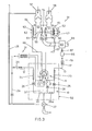
- a flueric partial pressure of oxygen sensor device 50 comprising a flueric bridge partial pressure sensor 10 matched with a two-stage high input impedance flueric laminar flow proportional amplifier 11, as described above with reference to Figure 1, is used to control a mixing valve 51; the combination providing apparatus for regulation of the composition of oxygen and air for supply to a regulator of an aviator's breathable gas system (not shown).
- a mixing valve 51 provides an improvement over the sensor device and mixing valve shown in Figure 2 of U.K. Patent Application No. 20162789A by omitting the absolute-pressure reference device, its operating gas flow and associated ducting, etc., of the arrangement of the Application.
- the mixing valve 51 is similar to, but simpler than, that disclosed in U.K. Patent Application No. 2016278A and includes a proportioning valve 52 operable in response to pressure signals generated by the sensor device 50.
- the mixing valve 51 comprises a mixing chamber 54 positioned between two inlet chambers-55, 56 which admit air and oxygen from respective inlets 57, 58. Admission to the mixing chamber 54 from the chambers 55, 56 is by way of two ports that have circumscribing annular valve seats exposed to the interior of the mixing chamber 54.
- the proportioning valve 52 includes two valve heads 59, 60 arranged for co-operation with the annular valve seats, being disposed interiorly of the mixing chamber 54 on a common spindle 61 that terminates at each end in a pneumatic actuator arrangement 62, 63.
- a low rate compression spring 53 is included in one actuator 63 in order to bias the valve heads 59, 60 towards closing the air inlet while opening the oxygen inlet in order to provide a 'fail-safe' condition.
- the actuator arrangements 62, 63 include diaphragm assemblies 64, 65, respectively, of which the facing sides are connected to ambient pressure whilst their respective remote sides are connected to the pressure output signal passages 67, 68 from the amplifier 11 of the sensor device 50.
- the air supply line 28 for supplying air to operate the aspirator 27 of the sensor device 50 is connected as a tapping to the air inlet 57.
- Branch conduit 29 is connected to the air supply line 28 for supplying clean dried air to the inlet arrangement 31 of the amplifier 11 and to the reference-gas supply line 20.
- the sample-gas supply line 19, for feeding to the sensor device 50 is connected at one end to the delivery line 66 of the mixing valve 51 which conveys air or oxygen or a mixture thereof towards the regulator of the aviator's breathing system (not shown). This connection is made in the vicinity of the regulator and terminates interiorily of a 23 cc capacity 85 which forms part of the delivery line 66.
- the other end of the supply line 19 terminates at the shroud 17, which shields the filtering end of the sample-gas line 13 of the sensor device 50, and includes a capacity 86 of 14.75 cc which is situated downstream of a flow restrictor 87 that provides an orifice of 0.17 mm diameter.
- the aspirator 27 generates suction to draw reference-gas and sample-gas through the sensor 10 and to effect operation of the main jets of the amplifier 11, as described hereinbefore with reference to Figure 1.
- the signal pressures in the outlet signal passages 21, 22 of the sensor 11 are in balance owing to the. flow rates appropriate to the partial pressure of oxygen for 1,500 m. obtaining in the inlet legs 12, 13.
- the low rate spring 53 is arranged to oppose the biased pressure output of the amplifier 11 such that it positions the proportioning valve 52 so as to proportion a flow of oxygen past valve head 60 and air past valve head 59 to obtain oxygen-enriched air having a partial pressure of oxygen corresponding to an 1,500 m. altitude condition.
- the flow rates in the two inlet legs 12, 13 modify until the pressure output signal from the sensor 10 becomes again balanced. Then the oxygen-enriched air, being supplied to the regulator of the aviator's breathable gas supply system (not shown) by way of the mixing chamber outlet 66, is restored to a condition having a partial pressure of oxygen equivalent to the 1,500 m. altitude condition.
- Descent of the cabin altitude equivalent tends to cause slight over-enrichment of the air that is being supplied to the aviator and the effect of the changing reference and sample gases in their respective inlet legs 12, 13 operates in reverse to that just described, so that the output from the amplifier 11 causes the proportioning valve 52 to move towards closing the oxygen valve head 60 while correspondingly opening the air valve head 59 until the fluid flow conditions in the two legs of the sensor 10 return to the corresponding 1,500 m. altitude condition and a balanced pressure output is again established and sensed in the control pressure regions of the first stage of the amplifier 11. Below the preselected set-point altitude equivalent (i.e. preselected partial pressure of oxygen) the apparatus tends to supply slightly oxygen-enriched air in proportion to the slope of the amplifier output line and the amplifier differential output pressure required to oppose the fail-safe spring 53.
- preselected set-point altitude equivalent i.e. preselected partial pressure of oxygen
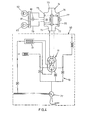
- a flueric partial pressure sensor device 50 is used in combination with a pressure responsive device in the form of an indicator or warning device indicating the state of a partial pressure of oxygen condition.
- the sensor device 50 is identical to that shown in Figure 3 and, therefore, will not again be described.
- the pressure output connections of the amplifier 11 are connected to a pressure transducer 70 which in simple form comprises a housing 71 providing a chamber that is divided by a flexible diaphragm 72 into two sub-chambers 73, 74.
- the diaphragm 72 is held in a null working position between two opposing low rate compression springs 75, 76, one of which 76 is supported in a screw- type adjuster 77 in sub-chamber 74.
- a micro-switch 78 is mounted in sub-chamber 73 and arranged'to be operated by deflection of the diaphragm 72.
- the micro-switch forms part of an electrical circuit 79 that includes a power source 80 and an indicator 81 such as an audible or visual device. Provision may be made for visual indication to be continuous by making the micro-switch 78 two-way and providing a form of indicator 81 showing alternative indication, e,g. different coloured lights 82, 83, dependent upon which side of the null position the diaphragm 72 is urged to be by the output signal from the amplifier 11.
- the pressure output connections of the amplifier 11 are connected to the sub-chambers 74, 73, reapectively.
- the sensor device 50 operates-as hereinbefore described with reference to the embodiment of Figure 3.
- the 'set-point' i.e. the partial pressure of oxygen required to be monitored is, say, 17.33 kPa
- the diaphragm 27 is deflected towards sub-chamber 74, owing to the pressure output signals from the sensor 10 being in balance, and the inherent bias of the amplifier 11 causing the micro-switch 78 to complete the circuit 79 to light bulb 82.
- the sensor 10 pressure output signals are unbalanced and the amplifier output modified so that the diaphragm 72 is deflected towards the other sub-chamber 73 and the micro-switch operated to complete the circuit in activation of light bulb 83.
Landscapes
- Physics & Mathematics (AREA)
- Health & Medical Sciences (AREA)
- Life Sciences & Earth Sciences (AREA)
- Chemical & Material Sciences (AREA)
- Analytical Chemistry (AREA)
- Biochemistry (AREA)
- General Health & Medical Sciences (AREA)
- General Physics & Mathematics (AREA)
- Immunology (AREA)
- Pathology (AREA)
- Sampling And Sample Adjustment (AREA)
- Respiratory Apparatuses And Protective Means (AREA)
Applications Claiming Priority (2)
| Application Number | Priority Date | Filing Date | Title |
|---|---|---|---|
| GB8008917 | 1980-03-17 | ||
| GB8008917 | 1980-03-17 |
Publications (3)
| Publication Number | Publication Date |
|---|---|
| EP0036285A2 true EP0036285A2 (de) | 1981-09-23 |
| EP0036285A3 EP0036285A3 (en) | 1982-05-12 |
| EP0036285B1 EP0036285B1 (de) | 1985-01-23 |
Family
ID=10512143
Family Applications (1)
| Application Number | Title | Priority Date | Filing Date |
|---|---|---|---|
| EP19810300995 Expired EP0036285B1 (de) | 1980-03-17 | 1981-03-10 | Pneumatischer Partialdruckdetektor |
Country Status (4)
| Country | Link |
|---|---|
| US (1) | US4407153A (de) |
| EP (1) | EP0036285B1 (de) |
| CA (1) | CA1162984A (de) |
| DE (1) | DE3168427D1 (de) |
Cited By (6)
| Publication number | Priority date | Publication date | Assignee | Title |
|---|---|---|---|---|
| US4530233A (en) * | 1983-07-18 | 1985-07-23 | Air Products And Chemicals, Inc. | Method and apparatus for distinguishing between different gas or gas mixtures using a flow tube |
| DE3505421A1 (de) * | 1984-02-20 | 1985-08-22 | Normalair-Garrett (Holdings) Ltd., Yeovil, Somerset | Molekularsieb-gasabscheidungseinrichtungen |
| US4594080A (en) * | 1984-02-20 | 1986-06-10 | Normalair-Garrett Holdings Ltd. | Molecular sieve type gas separation systems |
| EP0196157A1 (de) * | 1985-02-22 | 1986-10-01 | Normalair-Garrett (Holdings) Limited | Pneumatischer Partialdrucksensor |
| US4783205A (en) * | 1986-10-01 | 1988-11-08 | Normalair-Garrett (Holdings) Ltd. | Aircraft on-board gas generating apparatus |
| US5272907A (en) * | 1990-06-08 | 1993-12-28 | Instrumentarium Corporation | Method for the identification of gases |
Families Citing this family (11)
| Publication number | Priority date | Publication date | Assignee | Title |
|---|---|---|---|---|
| DE3271664D1 (en) * | 1981-09-09 | 1986-07-17 | Normalair Garrett Ltd | Gas flow responsive signal output means |
| US4709575A (en) * | 1986-05-05 | 1987-12-01 | Litton Systems, Inc. | Fluidic oxygen sensor monitor |
| GB2199166B (en) * | 1986-12-08 | 1990-08-15 | Normalair Garrett | Flueric partial pressure sensors |
| FI80606C (fi) * | 1987-10-05 | 1990-07-10 | Kemira Oy | Foerfarande foer reglering av luftmaongden som matas in i en gasmask samt en gasmask som genomfoer denna foerfarande. |
| US4856338A (en) * | 1988-10-03 | 1989-08-15 | The United States Of America As Represented By The Secretary Of The Army | Technique for null balancing fluidic circuits |
| US5596154A (en) * | 1995-09-21 | 1997-01-21 | Enviroplan, Inc. | Dilution control method and apparatus |
| US6148659A (en) * | 1998-10-08 | 2000-11-21 | Traina; John E. | Gas concentration monitor having a bridge configured flow system |
| US8302603B1 (en) * | 2007-03-22 | 2012-11-06 | Weber David W | Aircrew rebreather system |
| CN104136905B (zh) * | 2012-02-22 | 2016-03-16 | 野猫发现技术公司 | 用于利用一体式气体组分测量装置进行气体吸附测量和气体混合的设备 |
| GB2528025B (en) * | 2014-05-02 | 2019-03-06 | Fathom Systems Ltd | Determining the partial pressure of a gas in a pressure vessel |
| GB2535691B (en) * | 2015-01-13 | 2018-01-17 | Fathom Systems Ltd | Determining the partial pressure of a gas, calibrating a pressure sensor |
Family Cites Families (7)
| Publication number | Priority date | Publication date | Assignee | Title |
|---|---|---|---|---|
| US3490408A (en) * | 1966-06-06 | 1970-01-20 | Ite Imperial Corp | Alarm circuits and systems |
| US3665947A (en) * | 1970-01-05 | 1972-05-30 | Bendix Corp | Fluidic sensing circuit and pressure regulator |
| CA942968A (en) * | 1971-01-11 | 1974-03-05 | Royston A. Stubbs | Binary gas composition measurement and control apparatus |
| US3771348A (en) * | 1972-02-28 | 1973-11-13 | Us Army | Analog flueric gas concentration sensor |
| US4008601A (en) * | 1975-06-16 | 1977-02-22 | The United States Of America As Represented By The Secretary Of The Army | Fluidic partial pressure sensor |
| US4100789A (en) * | 1977-07-28 | 1978-07-18 | The United States Of America As Represented By The Secretary Of The Army | Fluidic partial pressure sensor |
| GB2016278B (en) * | 1977-09-26 | 1982-03-03 | Normalair Garrett Ltd | Breathable gas delivery regulators |
-
1981
- 1981-03-10 DE DE8181300995T patent/DE3168427D1/de not_active Expired
- 1981-03-10 EP EP19810300995 patent/EP0036285B1/de not_active Expired
- 1981-03-13 US US06/243,499 patent/US4407153A/en not_active Expired - Fee Related
- 1981-03-17 CA CA000373198A patent/CA1162984A/en not_active Expired
Cited By (7)
| Publication number | Priority date | Publication date | Assignee | Title |
|---|---|---|---|---|
| US4530233A (en) * | 1983-07-18 | 1985-07-23 | Air Products And Chemicals, Inc. | Method and apparatus for distinguishing between different gas or gas mixtures using a flow tube |
| DE3505421A1 (de) * | 1984-02-20 | 1985-08-22 | Normalair-Garrett (Holdings) Ltd., Yeovil, Somerset | Molekularsieb-gasabscheidungseinrichtungen |
| FR2559926A1 (fr) * | 1984-02-20 | 1985-08-23 | Normalair Garrett Ltd | Dispositif de separation de gaz du type a tamis moleculaire |
| US4594080A (en) * | 1984-02-20 | 1986-06-10 | Normalair-Garrett Holdings Ltd. | Molecular sieve type gas separation systems |
| EP0196157A1 (de) * | 1985-02-22 | 1986-10-01 | Normalair-Garrett (Holdings) Limited | Pneumatischer Partialdrucksensor |
| US4783205A (en) * | 1986-10-01 | 1988-11-08 | Normalair-Garrett (Holdings) Ltd. | Aircraft on-board gas generating apparatus |
| US5272907A (en) * | 1990-06-08 | 1993-12-28 | Instrumentarium Corporation | Method for the identification of gases |
Also Published As
| Publication number | Publication date |
|---|---|
| DE3168427D1 (de) | 1985-03-07 |
| CA1162984A (en) | 1984-02-28 |
| EP0036285A3 (en) | 1982-05-12 |
| EP0036285B1 (de) | 1985-01-23 |
| US4407153A (en) | 1983-10-04 |
Similar Documents
| Publication | Publication Date | Title |
|---|---|---|
| US4407153A (en) | Flueric partial pressure sensors | |
| US4687013A (en) | Flueric partial pressure sensor | |
| US4240419A (en) | Breathable gas delivery regulators | |
| US4328823A (en) | Oxygen flow ratio controller for anesthesia apparatus | |
| US3739799A (en) | Continuous flow anesthesia apparatus | |
| JPS6222637B2 (de) | ||
| US4648397A (en) | Electronically compensated pressure dilution demand regulator | |
| EP0200737A1 (de) | Künstliches beatmungssystem. | |
| EP0087935A2 (de) | Flüssigkeitsfluss-Steuersystem | |
| US4856507A (en) | Two main piloted valves demand regulator for aviators | |
| GB1473892A (en) | Apparatus for controlling fluid flow | |
| US2185997A (en) | Means for supplying to individual persons an oxygenated gas mixture | |
| US2378468A (en) | Pressure regulator | |
| EP0121796B1 (de) | Sauerstoffpartialdruckregler für ein Druckwechseladsorptionssystem | |
| US4537607A (en) | Gas flow controllers for aircraft molecular sieve type gas separation systems | |
| US4823593A (en) | Flueric partial pressure sensors | |
| US4127129A (en) | Oxygen regulator | |
| US4476708A (en) | Flow controller | |
| US4594080A (en) | Molecular sieve type gas separation systems | |
| EP0327396A3 (de) | Vorrichtung zum Zuführen einer Atmungsprobe zu einem Solid-State-Fühler | |
| US4141496A (en) | Pneumatic thermostat | |
| US2985357A (en) | Injectors | |
| CA1296547C (en) | Fluidic oxygen sensor monitor | |
| US4589436A (en) | Oxygen partial pressure controller for a pressure swing adsorption system | |
| US3712325A (en) | Gas mixer |
Legal Events
| Date | Code | Title | Description |
|---|---|---|---|
| PUAI | Public reference made under article 153(3) epc to a published international application that has entered the european phase |
Free format text: ORIGINAL CODE: 0009012 |
|
| AK | Designated contracting states |
Designated state(s): BE DE FR GB IT SE |
|
| PUAL | Search report despatched |
Free format text: ORIGINAL CODE: 0009013 |
|
| AK | Designated contracting states |
Designated state(s): BE DE FR GB IT SE |
|
| 17P | Request for examination filed |
Effective date: 19820602 |
|
| ITF | It: translation for a ep patent filed | ||
| GRAA | (expected) grant |
Free format text: ORIGINAL CODE: 0009210 |
|
| AK | Designated contracting states |
Designated state(s): BE DE FR GB IT SE |
|
| REF | Corresponds to: |
Ref document number: 3168427 Country of ref document: DE Date of ref document: 19850307 |
|
| ET | Fr: translation filed | ||
| PLBE | No opposition filed within time limit |
Free format text: ORIGINAL CODE: 0009261 |
|
| STAA | Information on the status of an ep patent application or granted ep patent |
Free format text: STATUS: NO OPPOSITION FILED WITHIN TIME LIMIT |
|
| 26N | No opposition filed | ||
| PG25 | Lapsed in a contracting state [announced via postgrant information from national office to epo] |
Ref country code: SE Effective date: 19890311 |
|
| PG25 | Lapsed in a contracting state [announced via postgrant information from national office to epo] |
Ref country code: BE Effective date: 19890331 |
|
| BERE | Be: lapsed |
Owner name: NORMALAIR-GARRETT (HOLDINGS) LTD Effective date: 19890331 |
|
| PGFP | Annual fee paid to national office [announced via postgrant information from national office to epo] |
Ref country code: GB Payment date: 19900228 Year of fee payment: 10 |
|
| PGFP | Annual fee paid to national office [announced via postgrant information from national office to epo] |
Ref country code: FR Payment date: 19900319 Year of fee payment: 10 |
|
| ITTA | It: last paid annual fee | ||
| PGFP | Annual fee paid to national office [announced via postgrant information from national office to epo] |
Ref country code: DE Payment date: 19900430 Year of fee payment: 10 |
|
| PG25 | Lapsed in a contracting state [announced via postgrant information from national office to epo] |
Ref country code: GB Effective date: 19910310 |
|
| GBPC | Gb: european patent ceased through non-payment of renewal fee | ||
| PG25 | Lapsed in a contracting state [announced via postgrant information from national office to epo] |
Ref country code: FR Effective date: 19911129 |
|
| PG25 | Lapsed in a contracting state [announced via postgrant information from national office to epo] |
Ref country code: DE Effective date: 19920101 |
|
| REG | Reference to a national code |
Ref country code: FR Ref legal event code: ST |
|
| EUG | Se: european patent has lapsed |
Ref document number: 81300995.8 Effective date: 19900124 |