EP0036287B1 - Lance monitor pour projeter du liquide - Google Patents
Lance monitor pour projeter du liquide Download PDFInfo
- Publication number
- EP0036287B1 EP0036287B1 EP81301004A EP81301004A EP0036287B1 EP 0036287 B1 EP0036287 B1 EP 0036287B1 EP 81301004 A EP81301004 A EP 81301004A EP 81301004 A EP81301004 A EP 81301004A EP 0036287 B1 EP0036287 B1 EP 0036287B1
- Authority
- EP
- European Patent Office
- Prior art keywords
- head
- housing
- passage
- liquid
- cross
- Prior art date
- Legal status (The legal status is an assumption and is not a legal conclusion. Google has not performed a legal analysis and makes no representation as to the accuracy of the status listed.)
- Expired
Links
- 239000007788 liquid Substances 0.000 claims abstract description 19
- 238000007789 sealing Methods 0.000 claims abstract description 5
- 238000011144 upstream manufacturing Methods 0.000 claims description 5
- 238000004891 communication Methods 0.000 claims description 2
- XLYOFNOQVPJJNP-UHFFFAOYSA-N water Substances O XLYOFNOQVPJJNP-UHFFFAOYSA-N 0.000 description 14
- 229910000838 Al alloy Inorganic materials 0.000 description 2
- 238000005266 casting Methods 0.000 description 2
- 239000006260 foam Substances 0.000 description 2
- 238000006243 chemical reaction Methods 0.000 description 1
- 230000000295 complement effect Effects 0.000 description 1
- 230000008878 coupling Effects 0.000 description 1
- 238000010168 coupling process Methods 0.000 description 1
- 238000005859 coupling reaction Methods 0.000 description 1
- 238000006073 displacement reaction Methods 0.000 description 1
- 230000000694 effects Effects 0.000 description 1
- 239000012530 fluid Substances 0.000 description 1
- 239000011888 foil Substances 0.000 description 1
- 238000009434 installation Methods 0.000 description 1
- 238000005065 mining Methods 0.000 description 1
- 239000000203 mixture Substances 0.000 description 1
- NJPPVKZQTLUDBO-UHFFFAOYSA-N novaluron Chemical compound C1=C(Cl)C(OC(F)(F)C(OC(F)(F)F)F)=CC=C1NC(=O)NC(=O)C1=C(F)C=CC=C1F NJPPVKZQTLUDBO-UHFFFAOYSA-N 0.000 description 1
- 230000003019 stabilising effect Effects 0.000 description 1
- 230000003068 static effect Effects 0.000 description 1
- 238000005406 washing Methods 0.000 description 1
Images


Classifications
-
- F—MECHANICAL ENGINEERING; LIGHTING; HEATING; WEAPONS; BLASTING
- F16—ENGINEERING ELEMENTS AND UNITS; GENERAL MEASURES FOR PRODUCING AND MAINTAINING EFFECTIVE FUNCTIONING OF MACHINES OR INSTALLATIONS; THERMAL INSULATION IN GENERAL
- F16L—PIPES; JOINTS OR FITTINGS FOR PIPES; SUPPORTS FOR PIPES, CABLES OR PROTECTIVE TUBING; MEANS FOR THERMAL INSULATION IN GENERAL
- F16L27/00—Adjustable joints; Joints allowing movement
- F16L27/08—Adjustable joints; Joints allowing movement allowing adjustment or movement only about the axis of one pipe
- F16L27/087—Joints with radial fluid passages
-
- A—HUMAN NECESSITIES
- A62—LIFE-SAVING; FIRE-FIGHTING
- A62C—FIRE-FIGHTING
- A62C31/00—Delivery of fire-extinguishing material
- A62C31/02—Nozzles specially adapted for fire-extinguishing
- A62C31/24—Nozzles specially adapted for fire-extinguishing attached to ladders, poles, towers, or other structures with or without rotary heads
-
- B—PERFORMING OPERATIONS; TRANSPORTING
- B05—SPRAYING OR ATOMISING IN GENERAL; APPLYING FLUENT MATERIALS TO SURFACES, IN GENERAL
- B05B—SPRAYING APPARATUS; ATOMISING APPARATUS; NOZZLES
- B05B15/00—Details of spraying plant or spraying apparatus not otherwise provided for; Accessories
- B05B15/60—Arrangements for mounting, supporting or holding spraying apparatus
- B05B15/65—Mounting arrangements for fluid connection of the spraying apparatus or its outlets to flow conduits
- B05B15/652—Mounting arrangements for fluid connection of the spraying apparatus or its outlets to flow conduits whereby the jet can be oriented
- B05B15/654—Mounting arrangements for fluid connection of the spraying apparatus or its outlets to flow conduits whereby the jet can be oriented using universal joints
Definitions
- a monitor comprises a nozzle borne by a mechanism which permits the orientation of the nozzle to be adjusted by pivotal movements about two orthogonal axes-a generally vertical axis about which the nozzle can be pivoted to traverse its jet from side to side, and a generally horizontal axis about which the nozzle can be pivoted to adjust its angular elevation or depression.
- Such devices may be embodied as portable freestanding units to be set up as required at the scene of a fire, or may be mounted on trailers or self-propelled fire fighting vehicles, or may be used in fixed installations at tanker jetties, oil refineries or other fire risk areas.
- monitors in accordance with the invention may nevertheless find application in other fields of use, e.g. in certain forms of mining and industrial washing processes, and generally where there is a need to control the direction through space of relatively high pressure, high flowrate jets of water or other liquids.
- a 'spherical head monitor' The type of monitor with which the invention is more particularly concerned is that which will be hereinafter referred to as a 'spherical head monitor'.
- the head is borne for pivotal movement relative to the housing about a generally horizontal axis so as to provide adjustment of the angular elevation or depression of the nozzle, throughout the permitted range of such movement the frusto-spherical surface of the head forming a sliding seal against the housing to maintain the aforesaid chamber liquid-tight.
- the assembly of head and housing may also be borne for pivotal movement as a whole about a generally vertical axis, thereby to traverse the jet which issues from the nozzle from side to side.
- a spherical head monitor is known e.g. from DE-B-1559624.
- the head is borne by a housing the internal surface of which is itself frusto-spherical and complementary to the frusto-spherical surface of the head so that the head and housing have a ball-and-socket relationship, although pivotal movement of the head relative to the housing is limited to a single (horizontal) axis by appropriate bearings.
- the housing is carried at the end of an elbow duct which can be pivoted about a vertical axis for traverse adjustment of the liquid jet.
- the margins of the inlet to the head passage lie closely adjacent to the internal surface of the housing and, in order to provide sufficient rate of flow of liquid from the elbow duct into the head passage at different angular positions of the head relative to the housing, the inlet portion of the passage through the head is widened, in the direction perpendicular to the pivot axis of the head, as compared with the downstream portion of that passage and with the bore of the elbow duct. There is, therefore, a sudden increase and then decrease in the flowpath cross-section in passing from the elbow duct into the head.
- a further drawback of the monitor disclosed in DE-B-1559624 is that the sealing means provided on the housing for cooperation with the frusto-spherical surface of the head must be located in front of the pivot axis of the head relative to the housing (i.e. downstream of that axis in the sense of liquid flow through the head). This is necessary in order to accommodate the pivot angle of the head bearing in mind that the upper and lower margins of the head passage inlet are flared apart as mentioned above.
- a consequence of this seal location is that the housing must be split into two parts to enable the head to be assembled into the housing.
- This seal location is also disadvantageous when considered in relation to the effects of the dynamic and hydraulic forces acting on the monitor. That is to say the reaction force of the liquid jet emerging from the head nozzle tends to press the head rearwardly away from contact with the seal while the static pressure in the chamber behind the head presses the seal forwards, again in the direction which is away from contact with the head.
- DE-A-2059536 Another such monitor is shown in DE-A-2059536.
- This also has a flared (circular) inlet to the passage through its head but in this case the diameter of the head passage is relatively small in comparison with the diameter of the frusto-sphere so that the margins of the inlet remain spaced from the internal surface of the housing over a range of elevation angles.
- a disadvantage of this ratio of head-to-passage diameters is, however, that only a small proportion of the cross-sectional area of the head is occupied by the passage so that for the monitor to handle a high volumetric flow rate of liquid an unduly large and heavy head and associated structure is required.
- the housing/head seal is located in front of the head's pivot axis, with corresponding disadvantages as discussed above.
- the latter object is recognised in DE-B-1559624 but cannot be fully achieved due to the selected geometrical relationship between the head and housing in the prior device.
- the present invention accordingly provides a spherical head monitor where the cross-sectional area of the chamber immediately upstream of the inlet of the head passage is greater than the cross-sectional area of said inlet, and throughout at least a major part of the range of pivotal movement of the head relative to the housing both the upper and lower margins of said inlet remain spaced from the internal surface of the housing; characterised in that the portion of the housing which seals against the frusto-spherical surface of the head lies in a plane which is spaced upstream from the axis about which the head pivots relative to the housing; the inlet of said passage is of elongate cross-section with the longer cross-sectional dimension thereof parallel with said axis; and the head is so configured that the cross-sectional area of the passage within the head which is available for liquid flow is at least approximately constant throughout the length of said passage which is encompassed by said frusto-sphere.
- the ratio of the diametral cross-sectional area of the aforesaid frusto- sphere to the mean cross-sectional area available for liquid flow within the length of said passage which is encompassed by said frusto- sphere is approximately 4:1.
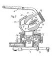
- FIG. 1 and 2 there is shown a portable, ground-standing spherical head monitor in accordance with the invention, its head 1 being pivoted about a horizontal axis in a housing 2, and the assembly of head 1 and housing 2 being pivoted about a vertical axis in the body 3, all as more fully described hereinafter.
- a handle bar 4 is attached to the head 1 in order to facilitate manual adjustment of its orientation.
- the monitor has a fixed front foot 5 and a pair of rear legs 6 which can be swung out from a stowed position beneath the body 3 ( Figure 2) to their operative, stabilising positions (Figure 1) when the monitor is set up for use.
- Inlet couplings 7 for water hoses are provided to each side of the body 3, water supplied to these inlets being lead through the body and housing 2 to the head 1 as will be more fully described hereinafter.
- the head 1 and housing 2 define together a chamber 8 from which water is lead through an inlet 9 in the rear of the head to a passage 10 extending through the head.
- the head has a frusto-spherical external surface 11 which forms a sliding seal against an 0-ring 12 held in the housing 2, to keep the chamber 8 watertight throughout the permitted range of pivotal movement of the head relative to the housing.
- From the spherical portion of the head there extends a short barrel portion 13 terminating in a threaded socket 14 to which may be coupled a water nozzle or foam branch pipe or an adaptor therefor (e.g. as indicated at 15 in Figure 1).
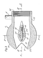
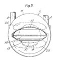
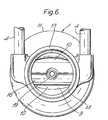
- the internal form of the head 1 appears from Figures 3-6.
- An integral centre body 16 extends transversely across the interior of the head, the head and centre body being formed from a single casting e.g. in aluminium alloy.
- a bore 17 is formed in the centre body, its axis passing through the geometrical centre of the frusto-spherical surface 11 of the head, and an axle 18 passes through the bore 17, the head being fastened on the axle by means of a pin 19 passing through aligned bores 20 and 21 in the centre body and axle.
- the axle 18 is mounted at each end in bearings 22 in the housing 2 ( Figure 4), thereby to provide the pivotal movement for angular elevation and depression of the head.
- a hand-operated clutch arrangement (not shown) whereby the axle can be selectively locked to the housing with the head in a set angular orientation.
- the centre body 16 is shaped as a streamlined foil pointing upstream in the sense of water flow through the head, and acts to guide the water smoothly past the obstruction represented by the transverse axle 18. It defines together with the internal surface 23 of the head a passage 10 of which the cross-sectional area available for water flow is approximately constant throughout its length and which involves no abrupt changes in either direction or form.
- the form of surface 23 blends smoothly from an elliptical section at the inlet 9 to a circular section at the barrel portion 13.
- the cross-sectional form of the passage 10 as viewed on the line V-V of Figure 3 is indicated at 24 in Figure 5.
- the housing 2 together with the head 1 is fastened to the top end of a vertical axle 25.
- This axle is mounted in bearings 26 in the body 3 for 360° rotation, thereby to provide unlimited traverse adjustment for the head.
- a hand-operated brake mechanism is provided at 27 whereby the housing 2 can be selectively locked to the body 3 with the head in a set traverse position.
- the axle 25 acts not only as a bearing member for the head but also to lead water to the chamber 8 from an annular chamber 28 formed in the body 3 and connected with the water inlets 7.
- the form of the axle is more clearly shown in Figures 7-9. It comprises an upper tubular portion 29 with a radiused edge at 30 and within which are provided four integral septa 31 and intervening profiled surfaces 32. In practice all these parts are formed from a single casting e.g. in aluminium alloy.
- the resultant structure defines four sectoral channels 33 leading upwardly along arcuate paths from respective inlet apertures 34 defined beneath the tubular portion 29 and between the septa 31.
- the apertures 34 communicate with the surrounding chamber 28, and they will remain in communication with that chamber irrespective of the relative rotational position of the axle 25 in the body 3. Water from chamber 28 is thus lead smoothly upwards through a 90° angle in four separate streams by the channels 33, to unite in the top end of the axle and thence pass into the chamber 8.
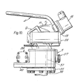
- FIG. 10 illustrates a similar type of monitor to that described above, like reference numerals being used to denote like parts, but in this case the monitor is adapted for remote as well as manual operation.
- the illustrated embodiment is shown mounted on a pedestal 35 and supplied with water from beneath by an inlet pipe 36.
- the side inlets 7 and chamber 28 described above are dispensed with and the pipe 36 leads sealingly into a plain tubular axle 37 in place of the axle 25 described above.
- two double-acting hydraulic actuators 38 and 39 are provided, to which the supplies of working fluid can be controlled remotely.
- Each actuator comprises a double-acting piston driving a sector gear so as to provide a rotary displacement output in dependence upon the differential pressure applied across the piston.
- the actuator 38 drives an extension of the axle 18 by which the head 1 of the monitor is pivoted in the housing 2, thereby to achieve remote adjustment of the orientation of the head in elevation and depression; and the actuator 39 drives the axle 37 via a ring gear located in the lower portion 40 of the body 3, thereby to achieve remote traverse adjustments for the head.
- a portable, ground-standing fire fighting monitor substantially as shown in Figures 1 to 9 has been constructed with an outlet (14) diameter of 3 inches (76 mm) and is capable of handling water flows of up to 1600 litres/minute at an operating pressure of 20.5 bar.
- the pedestal-mounted version of Figure 10, with the same diameter outlet, can handle flows of up to 2270 litres/minute at the same operating pressure.
Landscapes
- Engineering & Computer Science (AREA)
- General Engineering & Computer Science (AREA)
- Mechanical Engineering (AREA)
- Health & Medical Sciences (AREA)
- Public Health (AREA)
- Business, Economics & Management (AREA)
- Emergency Management (AREA)
- Fire-Detection Mechanisms (AREA)
- Examining Or Testing Airtightness (AREA)
- Measuring Volume Flow (AREA)
- Nozzles (AREA)
- Investigating Or Analysing Materials By Optical Means (AREA)
- Indicating Or Recording The Presence, Absence, Or Direction Of Movement (AREA)
Claims (7)
Priority Applications (1)
| Application Number | Priority Date | Filing Date | Title |
|---|---|---|---|
| AT81301004T ATE8580T1 (de) | 1980-03-13 | 1981-03-10 | Wendestrahlrohr zum verspritzen von fluessigkeit. |
Applications Claiming Priority (2)
| Application Number | Priority Date | Filing Date | Title |
|---|---|---|---|
| GB8008524 | 1980-03-13 | ||
| GB8008524 | 1980-03-13 |
Publications (2)
| Publication Number | Publication Date |
|---|---|
| EP0036287A1 EP0036287A1 (fr) | 1981-09-23 |
| EP0036287B1 true EP0036287B1 (fr) | 1984-07-25 |
Family
ID=10512064
Family Applications (1)
| Application Number | Title | Priority Date | Filing Date |
|---|---|---|---|
| EP81301004A Expired EP0036287B1 (fr) | 1980-03-13 | 1981-03-10 | Lance monitor pour projeter du liquide |
Country Status (7)
| Country | Link |
|---|---|
| US (2) | US4392618A (fr) |
| EP (1) | EP0036287B1 (fr) |
| AT (1) | ATE8580T1 (fr) |
| AU (1) | AU536147B2 (fr) |
| DE (1) | DE3164959D1 (fr) |
| GB (1) | GB2071527B (fr) |
| ZA (1) | ZA811588B (fr) |
Families Citing this family (29)
| Publication number | Priority date | Publication date | Assignee | Title |
|---|---|---|---|---|
| WO1983003768A1 (fr) * | 1982-05-04 | 1983-11-10 | The British Hydromechanics Research Association | Lance anti-feu |
| US4674686B1 (en) * | 1984-09-28 | 1999-08-10 | Elkhart Brass Mfg Co | Portable fire apparatus monitor |
| ATE107467T1 (de) * | 1990-04-11 | 1994-07-15 | Nomix Chipman Ltd | Gerät zum ausbringen von flüssigkeit. |
| US5249632A (en) | 1990-09-26 | 1993-10-05 | Helitactics Ltd. | Remote nozzle unit |
| US5204069A (en) * | 1991-10-07 | 1993-04-20 | Westvaco Corporation | Recovery boiler smelt shattering spray |
| DE4226336A1 (de) * | 1992-08-08 | 1994-02-10 | Emilia Steinicke | Reinigungsgerät für Kanäle oder Rohre |
| US5425505A (en) * | 1993-10-13 | 1995-06-20 | Jones; Jerry D. | Portable ground standing fire fighting monitor |
| SE502165C2 (sv) * | 1993-12-13 | 1995-09-04 | Svenska Skum Ab | Hydrostatiskt lager för strålkanon |
| US5848750A (en) * | 1996-08-21 | 1998-12-15 | Envirocare International, Inc. | Atomizing nozzle |
| US5899276A (en) * | 1997-09-10 | 1999-05-04 | Crash Rescue Equipment Service, Inc. | Bumper-mounted extensible turret |
| WO2000021614A1 (fr) * | 1998-10-14 | 2000-04-20 | Williams Fire & Hazard Control, Inc. | Appareil portable de lutte contre les incendies pouvant etre fixe au mur |
| US6305621B1 (en) | 2000-03-01 | 2001-10-23 | Task Force Tips, Inc. | Pivoting fluid conduit joint and one-way brake |
| US6354320B1 (en) | 2000-03-01 | 2002-03-12 | Task Force Tips, Inc. | Acceleration sensitive shut off valve for firefighting equipment |
| US6786426B1 (en) | 2002-08-13 | 2004-09-07 | Elkhart Brass Manufacturing Co. | Fire apparatus monitor |
| USD479314S1 (en) | 2002-08-23 | 2003-09-02 | Elkhart Brass Manufacturing Company, Inc. | Fire fighting monitor |
| US20080061172A1 (en) * | 2006-09-12 | 2008-03-13 | Trapp James M | High pressure monitor |
| US7644777B2 (en) * | 2003-10-14 | 2010-01-12 | Elkhart Brass Manufacturing Company, Inc. | Fire-fighting monitor |
| US7137578B2 (en) * | 2003-12-26 | 2006-11-21 | Task Force Tips, Inc. | Segmented monitor |
| US20070138073A1 (en) * | 2005-04-13 | 2007-06-21 | Matthews David S | Device for dispersing and distributing a fluid |
| US20060231642A1 (en) * | 2005-04-13 | 2006-10-19 | Matthews David S | Device for dispersing and distributing a fluid |
| WO2009006308A1 (fr) * | 2007-06-29 | 2009-01-08 | Elkhart Brass Manufacturing Company, Inc. | Appareil de surveillance de lutte contre les incendies |
| RU2372124C1 (ru) * | 2008-05-04 | 2009-11-10 | Закрытое Акционерное Общество "Инженерный Центр Пожарной Робототехники "Эфэр" | Пожарный монитор |
| US9067092B2 (en) * | 2008-05-09 | 2015-06-30 | Elkhart Brass Manufacturing Company, Inc. | Compact fire fighting monitor |
| RU2375094C1 (ru) * | 2008-05-19 | 2009-12-10 | Закрытое Акционерное Общество "Инженерный Центр Пожарной Робототехники "Эфэр" | Пожарный монитор с осциллятором |
| CA2696361C (fr) * | 2009-03-19 | 2013-09-17 | Crystal Fountains Inc. | Dispositif de buse d'eau articule |
| RU2412733C1 (ru) * | 2009-11-18 | 2011-02-27 | Закрытое Акционерное Общество "Инженерный Центр Пожарной Робототехники "Эфэр" | Пожарный монитор с шаровым шарниром |
| US8944346B2 (en) * | 2010-01-04 | 2015-02-03 | Akron Brass Company | Rotatable flange for a water monitor |
| US8678022B2 (en) | 2012-06-22 | 2014-03-25 | Akron Brass Co. | Positionable outlet for a water monitor |
| CN115501527B (zh) * | 2018-11-13 | 2024-06-07 | 泰科消防产品有限合伙公司 | 消防用水监测器制动系统及方法 |
Family Cites Families (17)
| Publication number | Priority date | Publication date | Assignee | Title |
|---|---|---|---|---|
| US591120A (en) * | 1897-10-05 | James m | ||
| US20488A (en) * | 1858-06-08 | Apparatus for manufacture of beer | ||
| US255430A (en) * | 1882-03-28 | Stand hose-pipe | ||
| USRE20488E (en) | 1937-08-24 | Shower head | ||
| GB190901295A (en) * | 1909-01-19 | 1909-06-24 | E A White Ltd | Ball Joint Attachment for Syringes for Spraying Insecticides and other Liquids. |
| US1187588A (en) * | 1913-03-12 | 1916-06-20 | William M White | Hydraulic nozzle. |
| US1674693A (en) * | 1925-10-27 | 1928-06-26 | Macgregor Wallace | Portable folding fire-monitor stand |
| FR701709A (fr) * | 1929-11-20 | 1931-03-21 | Régulateur de jet de liquides | |
| US2111553A (en) * | 1936-10-15 | 1938-03-22 | Chew Yee Lain | Mining monitor or nozzle |
| FR1008630A (fr) * | 1948-05-04 | 1952-05-20 | Guinard Pompes | Perfectionnement aux lances de projection de produits extincteurs ou autres |
| US2895435A (en) * | 1954-03-15 | 1959-07-21 | Combustion Eng | Tilting nozzle for fuel burner |
| GB770330A (en) * | 1954-09-18 | 1957-03-20 | Alec Graham Westmoreland | Improvements in, or relating to, nozzle attachments for taps and the like |
| DE1851099U (de) * | 1961-08-21 | 1962-05-03 | Ludwig Kramer | Feuerloesch-breitstrahler. |
| FR1402975A (fr) | 1964-05-05 | 1965-06-18 | Lance fixe articulée | |
| GB1160996A (en) | 1967-04-07 | 1969-08-13 | Barking Brassware | Improvements in or relating to Spray Nozzle Assemblies |
| NL139891B (nl) * | 1968-10-21 | 1973-10-15 | Holleman Nv Maschf | Inrichting voor het onder een variabele hoek afleveren van een materiaalstroom. |
| DE2059536A1 (de) * | 1970-12-03 | 1972-06-08 | Willi Giese | Klein-Wasserwerfer |
-
1981
- 1981-03-03 AU AU68023/81A patent/AU536147B2/en not_active Ceased
- 1981-03-10 AT AT81301004T patent/ATE8580T1/de not_active IP Right Cessation
- 1981-03-10 GB GB8107483A patent/GB2071527B/en not_active Expired
- 1981-03-10 EP EP81301004A patent/EP0036287B1/fr not_active Expired
- 1981-03-10 ZA ZA00811588A patent/ZA811588B/xx unknown
- 1981-03-10 DE DE8181301004T patent/DE3164959D1/de not_active Expired
- 1981-03-13 US US06/243,305 patent/US4392618A/en not_active Expired - Fee Related
-
1983
- 1983-04-18 US US06/485,798 patent/US4506738A/en not_active Expired - Fee Related
Also Published As
| Publication number | Publication date |
|---|---|
| GB2071527A (en) | 1981-09-23 |
| DE3164959D1 (en) | 1984-08-30 |
| EP0036287A1 (fr) | 1981-09-23 |
| US4392618A (en) | 1983-07-12 |
| GB2071527B (en) | 1984-02-22 |
| AU536147B2 (en) | 1984-04-19 |
| ZA811588B (en) | 1982-04-28 |
| US4506738A (en) | 1985-03-26 |
| AU6802381A (en) | 1981-09-17 |
| ATE8580T1 (de) | 1984-08-15 |
Similar Documents
| Publication | Publication Date | Title |
|---|---|---|
| EP0036287B1 (fr) | Lance monitor pour projeter du liquide | |
| US8714466B2 (en) | Fire-fighting monitor with remote control | |
| US4793557A (en) | Firefighting monitor apparatus | |
| US6305620B1 (en) | Firefighting monitor apparatus | |
| US4826087A (en) | Manipulative device | |
| US9259746B2 (en) | Adjustable smooth bore nozzle | |
| US8424781B2 (en) | Power sprayer | |
| US3421702A (en) | Adjustable multiple fluid atomizing nozzle | |
| US7137578B2 (en) | Segmented monitor | |
| US4396356A (en) | Aspirator and aspirating system | |
| NO152075B (no) | Oppbevarings- og serveringsbeholder | |
| US4497442A (en) | Foam-applying nozzle having adjustable flow rates | |
| CA2339128A1 (fr) | Lance a mousse avec extraction et expulsion automatiques d'additif | |
| US3989109A (en) | Fire fighting turret | |
| EP2236893A2 (fr) | Joint de couplage amélioré pour diffuseur | |
| US6308362B1 (en) | Milling device for pipe cleaning and sanitation technology | |
| WO1993002881A1 (fr) | Ajutage de decharge | |
| US4684037A (en) | Perfected mechanical control device for ball valve type valve systems | |
| EP3259074B1 (fr) | Régulation de débit pour buse à jet plein et à brouillard | |
| US4231520A (en) | Liquid sprayer | |
| WO2002003149A1 (fr) | Dispositif de buse pour flexible et utilisation | |
| US4248385A (en) | Adjustable nozzle | |
| US10322421B2 (en) | Sprinkler | |
| US4607702A (en) | Fire monitors | |
| US7406984B2 (en) | Fluid distribution device |
Legal Events
| Date | Code | Title | Description |
|---|---|---|---|
| PUAI | Public reference made under article 153(3) epc to a published international application that has entered the european phase |
Free format text: ORIGINAL CODE: 0009012 |
|
| AK | Designated contracting states |
Designated state(s): AT DE FR IT NL |
|
| 17P | Request for examination filed |
Effective date: 19820315 |
|
| ITF | It: translation for a ep patent filed | ||
| GRAA | (expected) grant |
Free format text: ORIGINAL CODE: 0009210 |
|
| AK | Designated contracting states |
Designated state(s): AT DE FR IT NL |
|
| REF | Corresponds to: |
Ref document number: 8580 Country of ref document: AT Date of ref document: 19840815 Kind code of ref document: T |
|
| REF | Corresponds to: |
Ref document number: 3164959 Country of ref document: DE Date of ref document: 19840830 |
|
| ET | Fr: translation filed | ||
| PLBE | No opposition filed within time limit |
Free format text: ORIGINAL CODE: 0009261 |
|
| STAA | Information on the status of an ep patent application or granted ep patent |
Free format text: STATUS: NO OPPOSITION FILED WITHIN TIME LIMIT |
|
| 26N | No opposition filed | ||
| PGFP | Annual fee paid to national office [announced via postgrant information from national office to epo] |
Ref country code: AT Payment date: 19870119 Year of fee payment: 7 |
|
| PGFP | Annual fee paid to national office [announced via postgrant information from national office to epo] |
Ref country code: NL Payment date: 19870331 Year of fee payment: 7 |
|
| PG25 | Lapsed in a contracting state [announced via postgrant information from national office to epo] |
Ref country code: AT Effective date: 19880310 |
|
| PG25 | Lapsed in a contracting state [announced via postgrant information from national office to epo] |
Ref country code: NL Effective date: 19881001 |
|
| NLV4 | Nl: lapsed or anulled due to non-payment of the annual fee | ||
| PG25 | Lapsed in a contracting state [announced via postgrant information from national office to epo] |
Ref country code: FR Free format text: LAPSE BECAUSE OF NON-PAYMENT OF DUE FEES Effective date: 19881130 |
|
| REG | Reference to a national code |
Ref country code: FR Ref legal event code: ST |
|
| PG25 | Lapsed in a contracting state [announced via postgrant information from national office to epo] |
Ref country code: DE Effective date: 19891201 |