EP0036334B1 - Vehicle speed control - Google Patents
Vehicle speed control Download PDFInfo
- Publication number
- EP0036334B1 EP0036334B1 EP81301144A EP81301144A EP0036334B1 EP 0036334 B1 EP0036334 B1 EP 0036334B1 EP 81301144 A EP81301144 A EP 81301144A EP 81301144 A EP81301144 A EP 81301144A EP 0036334 B1 EP0036334 B1 EP 0036334B1
- Authority
- EP
- European Patent Office
- Prior art keywords
- vehicle
- speed
- signals
- retarder
- valves
- Prior art date
- Legal status (The legal status is an assumption and is not a legal conclusion. Google has not performed a legal analysis and makes no representation as to the accuracy of the status listed.)
- Expired
Links
- 239000012530 fluid Substances 0.000 claims description 12
- 230000000694 effects Effects 0.000 claims description 8
- 230000009467 reduction Effects 0.000 claims description 3
- 230000004044 response Effects 0.000 claims description 3
- 238000000034 method Methods 0.000 description 7
- 238000010276 construction Methods 0.000 description 3
- 238000005065 mining Methods 0.000 description 3
- 230000008569 process Effects 0.000 description 2
- 230000008054 signal transmission Effects 0.000 description 2
- 230000009471 action Effects 0.000 description 1
- 230000008878 coupling Effects 0.000 description 1
- 238000010168 coupling process Methods 0.000 description 1
- 238000005859 coupling reaction Methods 0.000 description 1
- 231100001261 hazardous Toxicity 0.000 description 1
- 230000000979 retarding effect Effects 0.000 description 1
Images

Classifications
-
- B—PERFORMING OPERATIONS; TRANSPORTING
- B60—VEHICLES IN GENERAL
- B60T—VEHICLE BRAKE CONTROL SYSTEMS OR PARTS THEREOF; BRAKE CONTROL SYSTEMS OR PARTS THEREOF, IN GENERAL; ARRANGEMENT OF BRAKING ELEMENTS ON VEHICLES IN GENERAL; PORTABLE DEVICES FOR PREVENTING UNWANTED MOVEMENT OF VEHICLES; VEHICLE MODIFICATIONS TO FACILITATE COOLING OF BRAKES
- B60T7/00—Brake-action initiating means
- B60T7/12—Brake-action initiating means for automatic initiation; for initiation not subject to will of driver or passenger
- B60T7/16—Brake-action initiating means for automatic initiation; for initiation not subject to will of driver or passenger operated by remote control, i.e. initiating means not mounted on vehicle
- B60T7/18—Brake-action initiating means for automatic initiation; for initiation not subject to will of driver or passenger operated by remote control, i.e. initiating means not mounted on vehicle operated by wayside apparatus
-
- H—ELECTRICITY
- H02—GENERATION; CONVERSION OR DISTRIBUTION OF ELECTRIC POWER
- H02P—CONTROL OR REGULATION OF ELECTRIC MOTORS, ELECTRIC GENERATORS OR DYNAMO-ELECTRIC CONVERTERS; CONTROLLING TRANSFORMERS, REACTORS OR CHOKE COILS
- H02P29/00—Arrangements for regulating or controlling electric motors, appropriate for both AC and DC motors
- H02P29/0016—Control of angular speed of one shaft without controlling the prime mover
Definitions
- the present invention relates to apparatus for controlling speed of a vehicle.
- the retarder of such a vehicle generally comprises a pneumatic coupling in the form of a pair of rotary members which cooperate one with another to define an air chamber therebetween, the arrangement being such that rotation of one member relative to the other to effect retardation of the vehicle is controlled by pressure of air directed into the chamber.
- the air pressure is controlled by a valve which generally is operated by a manually operable lever located adjacent a steering column of the vehicle.
- apparatus for controlling a vehicle having a retarder comprising a speed control sensor for sensing when the speed of the vehicle exceeds a reference speed, an electric circuit for controlling operation of a valve for controlling supply of working fluid to the retarder and a lamp adapted to be illuminated when the valve is operative in response to signals received from the sensor whereby a driver of the vehicle is provided with indication that the retarder is operative.
- a solution would be to provide the speed control sensor with a radio receiver for receiving signals from radio transmitters located along a route of a vehicle.
- the vehicle could be provided with an electric circuit comprising a comparator for comparing the speed of the vehicle with a reference speed represented in the form of radio signals received from each transmitter and adapted to generate output signals for effecting operation of an indicating device, such as a lamp.
- an indicating device such as a lamp.
- the signals transmitted from the respective transmitters could be indicative of different reference speeds and the output from the comparator could be arranged to control operation of a valve in the vehicle for effecting operation of the retarder in addition to effecting operation of the indicating device.
- valves for controlling supply of working fluid to the retarder, each valve being adapted to permit fluid to pass from a source to the retarder at a reduced pressure compared with the pressure of the fluid at source, operation of the valves being controlled by a timing device operable in response to output signals from the comparator so that valves are sequentially operated while the speed of the vehicle continues to exceed the reference speed whereby pressure of fluid supplied to the retarder is progressively increased in stages each of predetermined duration, and the increased pressure is maintained until manual controls of the vehicle are operated to effect reduction of the speed of the vehicle below the reference speed.
- an indicator is actuated immediately the speed of a vehicle exceeds a reference speed
- the retarder is not actuated until after an interval of a few seconds from operation of the indicator.
- a driver is warned that the speed of the vehicle exceeds a reference speed and is permitted sufficient time in which to apply brakes of the vehicle to retard the vehicle to a speed less than the reference speed.
- a valve is operated whereby working fluid at a pressure which is a percentage of the full pressure of the working fluid at source is permitted to pass to the retarder whereby the retarder is actuated resulting in sharp retardation of the vehicle.
- the process is repeated with operation a second indicator followed by operation of a second valve a few seconds later if the driver does not apply the brakes during the second interval to retard the vehicle to a speed less than the reference speed.
- Operation of the valve permits working fluid at a greater percentage of the full pressure than previously to pass to the retarder. The process may be repeated with additional indicators and corresponding valves.
- Drivers of vehicles provided with apparatus according to the invention therefore are provided with a warning when the speed of the vehicle exceeds a reference speed and further warning if the, or an earlier, warning is ignored, each warning being followed by an automatic sharp retardation of the vehicle.
- a receiver 1 carried on a vehicle (not shown) and adapted to receive radio signals from a transmitter 2 mounted adjacent a roadway along which the vehicle is driven.
- the receiver 1 is connected to a processor 26, also carried on the vehicle, by means of a line 3.
- the signals transmitted to the receiver 1 by the transmitter 2 are indicative of reference speed of the vehicle.
- the reference speed is selected by a dial 4 on the transmitter and may be any one of 8 k.p.h. (5 m.p.h.), 16 k.p.h. (10 m.p.h.), 24 k.p.h. (15 m.p.h.), 32 k.p.h. (20 m.p.h.) or 40 k.p.h. (25 m.p.h.), the signal transmitted by the transmitter varying in accordance with each corresponding selected speed.
- the signals thus received by the receiver 1 carried by a vehicle moving relative to the transmitter 2 are indicative of a selected reference speed for the vehicle when moving along the roadway adjacent which the transmitter is located and are transmitted from the receiver 1 to the processor 26 along the line 3.
- the processor 26 is provided with five pairs of lines 5a, 5h; 6a, 6h; 7a, 7h; 8a, 8h; and 9a, 9h, each being connected to a corresponding one of terminals 5b, 5i; 6b, 6i; 7b, 7i; 8b, 8i and 9b, 9i.
- the terminals are each included in corresponding switches comprising a second terminal 5c, 5j; 6c, 6j; 7c, 7j; 8c, 8j; and 8c, 9j connected to a line, 5d, 5k; 6d, 6k; 7d, 7k; 8d, 8k and 9d, 9k and switch contacts 5e, 51; 6e, 6t; 7e, 71; 8e, 8t; and 9e, 9t, the contacts of each pair being ganged.
- the lines 5d, 6d, 7d, 8d, and 9d are connected in parallel one with another and in series with a first output line 27 and the lines 5k, 6k, 7k, 8k, and 9k are connected in parallel one with another and in series with a second output line 28.
- the lines 5d, 6d, 7d, 8d, and 9d are tapped by a corresponding one of lines 5f, 6f, 7f, 8f, and 9f each of which is connected to a corresponding one of indicator lamps 5g, 6g, 7g, 8g, and 9g.
- the arrangement is such that the ganged pair of switch contacts 5e, 51; 6e, 61; 7e, 71; 8e, 81, and 9e, 91 are closed when corresponding relays (not shown) are operated and the relays are controlled to operate in sequence by the processor 26 on receipt of signals received from the sensor 24 indicative of an increase in speed of the vehicle.
- the contacts 7e, 71 are closed when the speed of the vehicle is greater than 17.6 k.p.h. (11 m.p.h.) but less than 25.6 k.p.h. (16 m.p.h.); the contacts 8e, 81 are closed when the speed of the vehicle is greater than 25.6 k.p.h. (16 m.p.h.) but less than 33.6 k.p.h. (21 m.p.h.) and the contacts 9e, 91 are closed when the speed of the vehicle is greater than 40 k.p.h. (25 m.p.h.).
- the processor 26 is arranged to transmit signals along the correponding pair of lines 5a, 5h; 6a, 6h; 7a, 7h; 8a, 8h and 9a, 9h when there is corelation between actual speed and reference speed.
- the reference speed selected by the dial 4 of the transmitter 2 is 16 k.p.h. (10 m.p.h.) and the speed of the vehicle is between 9.6 k.p.h. (6 m.p.h.) and 17.6 k.p.h. (11 m.p.h.), as indicated by the contacts 6e, 61 which are in a closed condition.
- the vehicle exceeds 16 k.p.ti.
- a signal is transmitted along the line 6a, across the contact 6e, along the line 6d and along the output line 27.
- the indicator lamp 6gv is illuminated indicating that the speed of the vehicle is equal to or has exceeded 16 k.p.h. (10 m.p.h.). If the speed subsequently falls below 16 k.p.h. (10 m.p.h.), the signal transmitted along the line 6a to the line 27 is removed, the lamp 6g, being extinguished, and a signal is transmitted along the line 6h, across the contact 61, along the line 6k and along the output line 28.
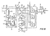
- FIG. 1 B shows apparatus 10 for controlling a pneumatic system of the vehicle.
- a portion of the braking system is shown at 12 and comprises three electrically operated valves 13, 14 & 15 each of which is connected to a common air supply through a conduit 16.
- An output of each of the valves 13, 14 8 ⁇ 15 is connected to a common feed conduit 17 which is connected to an input 18 of a slide valve 19.
- a second input 20 of the slide valve 19 has connected thereto a conduit 21.
- An outlet 22 of the slide valve 19 has connected thereto a conduit 23 for supplying a retarder (not shown) of the vehicle.
- the arrangement is such that, if none of the valves 13, 14 & 15 is operated air supply can only be directed through the conduit 21 to the slide valve 19 and through the slide valve and the conduit 23 to the retarder to retard the vehicle.
- the pressure of air directed to the conduit 21 is controlled by operation of a lever (not shown) on a control column (not shown) of the vehicle.
- the valve 13 is arranged such that, when operated, air supplied thereto is permitted to pass therethrough onward to the conduit 17 and to the slide valve 19, operating the slide valve and subsequently passing through the - conduit 23 to the retarder.
- the valves 14 and 15, when operated, also permit air supplied thereto to pass therethrough to the conduit 17 and the slide valve 19 and onward through the conduit 23 to the retarder.
- valves 13, 14 and 15 are controlled, in a manner to be described hereinafter, to operate consecutively and the arrangement is such that, when the valve 13 is operated, only 30% of the pressure of the air supplied to the conduit 16 passes to the conduit 17 but, when the valve 14 is operated while the valve 13 continues to be operated, 60% of the pressure of the air supplied to the conduit 16 passes to the conduit 17, and, when the valve 15 is operated while the valves 13 and 14 continue to be operated, 90% of the pressure of the air supplied to the conduit 16 is passed to the conduit 17.
- the lines 27, 28 are connected to input lines 29, 30 respectively of a latch and cancel unit 31.
- the input line 29 is connected to an output line 32 and is tapped by one end of a coil of a solenoid 33, the other end of which is earthed.
- the input line 28 is connected to a terminal 34 of a switch contact 35, the other terminal 36 of which is connected by a line 37 to a terminal 38 of another switch contact 39.
- the other terminal 40 of the switch contact 39 is connected by a line 41 to the output line 32.
- the latch and cancel unit 31 also includes a line 42 tapped from the line 37 and connected to a terminal 43 of a "cancel" switch 44, the other terminal 45 of the switch 44 having connected thereto one end of a coil of a solenoid 46, the other end of the coil being earthed.
- the line 42 is tapped by a line 42A connected to a buzzer 42B.
- the switch contact 35 is operated by the solenoid 33 and is normally open and the switch contact 39 is operated by the solenoid 46 and is normally closed.
- the output line 32 of the latch and cancel unit 31 is connected to an input line 47 of a timing unit 48.
- the timing unit 48 has three output lines 49, 50 and 51.
- the output line 49 is a continuation of the input line 47.
- the output line 50 is tapped from the input line 47 and includes a timer 52 for delaying transmission of signals received from the input 47 for five seconds until transmitting the signals along the line 50.
- the output line 51 is tapped from the input line 47 and includes a timer 53 for delaying transmission of signals received from the input line 47 for thirteen seconds until transmitting the signals along the output line 51.
- the output line 49 is connected to a terminal of the valve 13.
- the output line 50 is connected to a terminal of the valve 14 and the output line 51 is connected to a terminal of the valve 15.
- the output line 49 is tapped by a line 54 connected to a warning lamp 55 and a buzzer 56 in parallel.
- the output line 50 is tapped by a line 57 which is connected to a warning lamp 58 and a buzzer 59 in parallel and the output line 51 is tapped by a line 60 connected to a warning lamp 61 and a buzzer 62 in parallel.
- a voltage is supplied to output line 27 of the processor 26.
- a voltage is transmitted along the input line 29 and the output line 32 of the latch and cancel unit 31, the input line 47 of the timing unit 48 and the output line 49 of the timing unit to the terminal of the valve 13.
- the valve 13 consequently is operated and air at 30% of the pressure supplied to the conduit 16 is passed through the conduit 17, the slide valve 19 and the conduit 23 to the retarder thereby effecting retardation of the vehicle.
- a voltage is directed along the line 54 causing the warning lamp 55 to illuminate and the buzzer 56 to sound.
- a voltage is directed along the line 50 to the valve 14 causing the valve to operate and the pressure of air directed to the retarder through the conduits 17 and 23 to increase from 30% to 60% of the pressure of the air supplied to the conduit 16.
- a voltage also. is directed along the line 57 with a result that the warning lamp 58 is illuminated and the buzzer 59 sounded.
- the effect of 90% of full pressure of air directed to the retarder effects retardation of the vehicle to a speed below 16 k.p.h. (10 m.p.h.) with a result that the voltage applied to the output line 27 of the processor 26 is removed but a similar voltage is applied to the output line 28 of the processor 26 ensuring that the solenoid 33 remains energised and the switch contact 35 remains closed.
- the valves 13, 14 and 15 thus will continue to operate, the warning lamps 55, 58 and 61 will continue to be illuminated and the buzzers 56, 59 and 62 will continue to be sounded.
- the apparatus is "reset” by operation of the "cancel” button 44 which connects the terminals 43 and 45 causing energisation of the solenoid 46 with a result that the switch contact 39 is opened and voltage supply to the output 32 of the latch and cancel unit 31 is cut off.
- the valves 13, 14 and 15 therefore are deactivated and compressed air supply to the conduit 17 is cut off.
- the retarder thus is deactivated and retardation of the vehicle is discontinued by means of automatic operation of the retarder.
- the speed is automatically reduced by automatic operation of the retarder of the vehicle.
- the retarder continues to be automatically operated even after the vehicle speed has been automatically reduced to below the reference speed of 16 k.p.h. (10 m.p.h.) until the driver operates the "cancel" button 44.
- the apparatus will operate in similar manner if any one of the other reference speeds is selected by the dial 4 of the transmitter and the vehicle exceeds the reference speed.
- a plurality of transmitters 2 may be located at spaced intervals adjacent and along the roadway to monitor speed of vehicles passing therealong and to control the speed if in excess of a reference speed.
Landscapes
- Engineering & Computer Science (AREA)
- Transportation (AREA)
- Mechanical Engineering (AREA)
- Power Engineering (AREA)
- Transmission Of Braking Force In Braking Systems (AREA)
- Regulating Braking Force (AREA)
Priority Applications (1)
| Application Number | Priority Date | Filing Date | Title |
|---|---|---|---|
| AT81301144T ATE11836T1 (de) | 1980-03-19 | 1981-03-18 | Regelung der geschwindigkeit eines fahrzeuges. |
Applications Claiming Priority (4)
| Application Number | Priority Date | Filing Date | Title |
|---|---|---|---|
| GB8009243 | 1980-03-19 | ||
| GB8009243 | 1980-03-19 | ||
| GB8031051 | 1980-09-25 | ||
| GB8031051 | 1980-09-25 |
Publications (2)
| Publication Number | Publication Date |
|---|---|
| EP0036334A1 EP0036334A1 (en) | 1981-09-23 |
| EP0036334B1 true EP0036334B1 (en) | 1985-02-13 |
Family
ID=26274874
Family Applications (1)
| Application Number | Title | Priority Date | Filing Date |
|---|---|---|---|
| EP81301144A Expired EP0036334B1 (en) | 1980-03-19 | 1981-03-18 | Vehicle speed control |
Country Status (8)
| Country | Link |
|---|---|
| US (1) | US4433746A (da) |
| EP (1) | EP0036334B1 (da) |
| AU (1) | AU543105B2 (da) |
| BR (1) | BR8101589A (da) |
| DE (1) | DE3168855D1 (da) |
| DK (1) | DK120281A (da) |
| ES (1) | ES8201742A1 (da) |
| NO (1) | NO810907L (da) |
Families Citing this family (9)
| Publication number | Priority date | Publication date | Assignee | Title |
|---|---|---|---|---|
| JPS58113550A (ja) * | 1981-12-28 | 1983-07-06 | Aisin Seiki Co Ltd | 車輌速度制御装置 |
| US4608551A (en) * | 1983-07-05 | 1986-08-26 | Nippondenso Co., Ltd. | Speed alarm system for automotive vehicle |
| GB8408841D0 (en) * | 1984-04-05 | 1984-05-16 | Massey Ferguson Services Nv | Clutch engagement control system |
| GB8525096D0 (en) * | 1985-10-11 | 1985-11-13 | Lucas Ind Plc | Speed control unit |
| IT1226705B (it) * | 1987-08-14 | 1991-02-05 | Zahnradfabrik Friedrichshafen | Dispositivo per sorvegliare lo stato di comando di una unita' motrice di un autoveicolo. |
| AUPQ448499A0 (en) * | 1999-12-06 | 2000-01-06 | Myrtle, Richard | Speed controller |
| US20070156321A1 (en) * | 2005-12-29 | 2007-07-05 | Schad Jahan N | Speed regulation system for vehicles |
| CN104085304B (zh) * | 2014-06-30 | 2017-07-28 | 潍柴动力股份有限公司 | 基于缓速器的车速限制方法以及车速限制系统 |
| WO2017117002A1 (en) | 2015-12-28 | 2017-07-06 | Firstenergy Ventures Corp. | Vehicle speed control system |
Citations (6)
| Publication number | Priority date | Publication date | Assignee | Title |
|---|---|---|---|---|
| BE650138A (da) * | 1964-07-02 | 1964-11-03 | ||
| US3437188A (en) * | 1967-05-03 | 1969-04-08 | Gillett Tool Co | Electric speed control system for a fluid operated disc clutch |
| US3691525A (en) * | 1971-05-27 | 1972-09-12 | Rudolph M Mcclellan Sr | Vehicle speed indicator system |
| FR2207044A1 (da) * | 1972-11-17 | 1974-06-14 | Westinghouse Freins & Signaux | |
| US3948569A (en) * | 1973-09-05 | 1976-04-06 | Societe Nationale Industrielle Aerospatiale | Devices for controlling carbon disc brakes, more particularly for aircraft |
| US4193642A (en) * | 1974-06-24 | 1980-03-18 | Kelsey Hayes Co. | Skid control system |
Family Cites Families (16)
| Publication number | Priority date | Publication date | Assignee | Title |
|---|---|---|---|---|
| US2803743A (en) | 1951-03-07 | 1957-08-20 | Vehicules Guides Sur Pneumatiq | Control system for regulating the speed of vehicles |
| BE650130A (da) | 1963-07-16 | 1964-11-03 | ||
| US3396811A (en) | 1965-10-13 | 1968-08-13 | Grover W. Bowers | Remote control for automobiles |
| US3578108A (en) | 1969-02-19 | 1971-05-11 | Acf Ind Inc | Automotive cruise control system having fluidic control devices |
| AU430190B2 (en) | 1969-12-01 | 1972-11-16 | Raymond Campbell Paul | Method of and means for controlling traffic |
| US3686628A (en) | 1969-12-29 | 1972-08-22 | Arthur E Keller | Vehicle speed regulation, control means, and warning system |
| US3882973A (en) * | 1972-07-19 | 1975-05-13 | Caterpillar Tractor Co | Automatic retarder control system |
| FR2245185A5 (da) | 1973-09-20 | 1975-04-18 | Peugeot & Renault | |
| US3948856A (en) | 1973-09-26 | 1976-04-06 | Celanese Corporation | Acid interchange polymerization process for producing an aromatic polyester |
| FR2339174A1 (fr) | 1976-01-21 | 1977-08-19 | Ekman Adolphe | Procede et dispositif d'indication de niveaux de vitesse limites pour un vehicule automobile |
| US4136329A (en) | 1977-05-12 | 1979-01-23 | Transportation Logic Corporation | Engine condition-responsive shutdown and warning apparatus |
| AU3769678A (en) | 1977-07-13 | 1980-01-03 | Girling Ltd | Anti-skid vehicle braking systems |
| US4234051A (en) | 1978-07-26 | 1980-11-18 | Morris Jr Solon S | Driver alertness device |
| JPS5925867B2 (ja) | 1978-12-15 | 1984-06-21 | 株式会社日本自動車部品総合研究所 | 車輌用定速走行制御装置 |
| US4229727A (en) | 1979-04-23 | 1980-10-21 | Robert Gilhooley | Vehicle speed alarm |
| US4294204A (en) | 1979-06-18 | 1981-10-13 | Hurner Erwin E | Vehicle speed limiting device |
-
1981
- 1981-03-17 AU AU68433/81A patent/AU543105B2/en not_active Ceased
- 1981-03-17 NO NO810907A patent/NO810907L/no unknown
- 1981-03-18 DK DK120281A patent/DK120281A/da unknown
- 1981-03-18 EP EP81301144A patent/EP0036334B1/en not_active Expired
- 1981-03-18 US US06/245,205 patent/US4433746A/en not_active Expired - Fee Related
- 1981-03-18 BR BR8101589A patent/BR8101589A/pt unknown
- 1981-03-18 DE DE8181301144T patent/DE3168855D1/de not_active Expired
- 1981-03-18 ES ES501096A patent/ES8201742A1/es not_active Expired
Patent Citations (6)
| Publication number | Priority date | Publication date | Assignee | Title |
|---|---|---|---|---|
| BE650138A (da) * | 1964-07-02 | 1964-11-03 | ||
| US3437188A (en) * | 1967-05-03 | 1969-04-08 | Gillett Tool Co | Electric speed control system for a fluid operated disc clutch |
| US3691525A (en) * | 1971-05-27 | 1972-09-12 | Rudolph M Mcclellan Sr | Vehicle speed indicator system |
| FR2207044A1 (da) * | 1972-11-17 | 1974-06-14 | Westinghouse Freins & Signaux | |
| US3948569A (en) * | 1973-09-05 | 1976-04-06 | Societe Nationale Industrielle Aerospatiale | Devices for controlling carbon disc brakes, more particularly for aircraft |
| US4193642A (en) * | 1974-06-24 | 1980-03-18 | Kelsey Hayes Co. | Skid control system |
Also Published As
| Publication number | Publication date |
|---|---|
| AU543105B2 (en) | 1985-04-04 |
| BR8101589A (pt) | 1981-09-22 |
| US4433746A (en) | 1984-02-28 |
| DK120281A (da) | 1981-09-20 |
| NO810907L (no) | 1981-09-21 |
| ES501096A0 (es) | 1982-01-16 |
| EP0036334A1 (en) | 1981-09-23 |
| DE3168855D1 (en) | 1985-03-28 |
| ES8201742A1 (es) | 1982-01-16 |
| AU6843381A (en) | 1981-09-24 |
Similar Documents
| Publication | Publication Date | Title |
|---|---|---|
| US5255962A (en) | Electronic brake system for road vehicles | |
| US4407388A (en) | Collision prevention system | |
| EP0648658B1 (en) | Electrically operated parking brake system | |
| US6522969B2 (en) | Following distance displaying apparatus that changes alarming display according to operating states | |
| EP0036334B1 (en) | Vehicle speed control | |
| US4028662A (en) | Passing vehicle signalling apparatus | |
| US5415467A (en) | Automatic standstill brake for a motor vehicle equipped with an automatic transmission | |
| JPS60206730A (ja) | 変速機遠隔操作装置の診断装置 | |
| JP2002274217A (ja) | 車両用走行制御装置の状態表示装置 | |
| EP0036753B1 (en) | Overspeed engine control | |
| WO2016033255A1 (en) | Apparatus, method and system for monitoring towed vehicles in a tractor-trailer vehicle | |
| KR890700502A (ko) | 전자제어 유압 제동시스템 | |
| GB1457373A (en) | Flow dependent monitoring device for use in a pressure medium controlled brake system | |
| JPH07242164A (ja) | 追突警報装置付車両の自動ブレーキ装置 | |
| JPS6417107A (en) | Drive controller for self-traveling working vehicle | |
| EP0263668B1 (en) | Fluid pressure operable vehicle braking system | |
| JPH03176799A (ja) | 車間距離警報装置 | |
| JPH08133066A (ja) | 自動車用プログラム制御回路 | |
| JP2002067733A (ja) | 車両用走行制御装置 | |
| EP0513158A1 (en) | Control system | |
| KR100203488B1 (ko) | 차량 자동 주행 시스템 | |
| KR100187130B1 (ko) | 급제동시 추돌 사고 예방 시스템 | |
| JPH06278500A (ja) | 車両用衝突防止自動制動制御方法 | |
| FR2426946A1 (fr) | Procede pour le controle du temps de reaction des conducteurs d'automobiles pendant les parcours et dispositif pour la mise en oeuvre dudit procede | |
| KR970010220B1 (en) | Emergency lamp control apparatus of a car |
Legal Events
| Date | Code | Title | Description |
|---|---|---|---|
| PUAI | Public reference made under article 153(3) epc to a published international application that has entered the european phase |
Free format text: ORIGINAL CODE: 0009012 |
|
| AK | Designated contracting states |
Designated state(s): AT BE CH DE FR GB IT LU NL SE |
|
| 17P | Request for examination filed |
Effective date: 19810811 |
|
| ITF | It: translation for a ep patent filed | ||
| GRAA | (expected) grant |
Free format text: ORIGINAL CODE: 0009210 |
|
| AK | Designated contracting states |
Designated state(s): AT BE CH DE FR GB IT LI LU NL SE |
|
| PG25 | Lapsed in a contracting state [announced via postgrant information from national office to epo] |
Ref country code: SE Effective date: 19850213 Ref country code: NL Effective date: 19850213 Ref country code: LI Effective date: 19850213 Ref country code: CH Effective date: 19850213 Ref country code: BE Effective date: 19850213 Ref country code: AT Effective date: 19850213 |
|
| REF | Corresponds to: |
Ref document number: 11836 Country of ref document: AT Date of ref document: 19850215 Kind code of ref document: T |
|
| REF | Corresponds to: |
Ref document number: 3168855 Country of ref document: DE Date of ref document: 19850328 |
|
| PGFP | Annual fee paid to national office [announced via postgrant information from national office to epo] |
Ref country code: DE Payment date: 19850329 Year of fee payment: 5 |
|
| PG25 | Lapsed in a contracting state [announced via postgrant information from national office to epo] |
Ref country code: LU Free format text: LAPSE BECAUSE OF NON-PAYMENT OF DUE FEES Effective date: 19850331 |
|
| ET | Fr: translation filed | ||
| REG | Reference to a national code |
Ref country code: CH Ref legal event code: PL |
|
| NLV1 | Nl: lapsed or annulled due to failure to fulfill the requirements of art. 29p and 29m of the patents act | ||
| PLBE | No opposition filed within time limit |
Free format text: ORIGINAL CODE: 0009261 |
|
| STAA | Information on the status of an ep patent application or granted ep patent |
Free format text: STATUS: NO OPPOSITION FILED WITHIN TIME LIMIT |
|
| 26N | No opposition filed | ||
| PG25 | Lapsed in a contracting state [announced via postgrant information from national office to epo] |
Ref country code: GB Effective date: 19890318 |
|
| GBPC | Gb: european patent ceased through non-payment of renewal fee | ||
| PG25 | Lapsed in a contracting state [announced via postgrant information from national office to epo] |
Ref country code: FR Free format text: LAPSE BECAUSE OF NON-PAYMENT OF DUE FEES Effective date: 19891130 |
|
| PG25 | Lapsed in a contracting state [announced via postgrant information from national office to epo] |
Ref country code: DE Effective date: 19891201 |
|
| REG | Reference to a national code |
Ref country code: FR Ref legal event code: ST |