EP0036400A2 - Apparat zum kontinuierlichen Herstellen und Füllen von Beuteln - Google Patents
Apparat zum kontinuierlichen Herstellen und Füllen von Beuteln Download PDFInfo
- Publication number
- EP0036400A2 EP0036400A2 EP81830045A EP81830045A EP0036400A2 EP 0036400 A2 EP0036400 A2 EP 0036400A2 EP 81830045 A EP81830045 A EP 81830045A EP 81830045 A EP81830045 A EP 81830045A EP 0036400 A2 EP0036400 A2 EP 0036400A2
- Authority
- EP
- European Patent Office
- Prior art keywords
- sack
- apt
- fixed
- face plane
- movable
- Prior art date
- Legal status (The legal status is an assumption and is not a legal conclusion. Google has not performed a legal analysis and makes no representation as to the accuracy of the status listed.)
- Withdrawn
Links
Images




Classifications
-
- B—PERFORMING OPERATIONS; TRANSPORTING
- B65—CONVEYING; PACKING; STORING; HANDLING THIN OR FILAMENTARY MATERIAL
- B65B—MACHINES, APPARATUS OR DEVICES FOR, OR METHODS OF, PACKAGING ARTICLES OR MATERIALS; UNPACKING
- B65B1/00—Packaging fluent solid material, e.g. powders, granular or loose fibrous material, loose masses of small articles, in individual containers or receptacles, e.g. bags, sacks, boxes, cartons, cans, or jars
- B65B1/02—Machines characterised by the incorporation of means for making the containers or receptacles
-
- B—PERFORMING OPERATIONS; TRANSPORTING
- B31—MAKING ARTICLES OF PAPER, CARDBOARD OR MATERIAL WORKED IN A MANNER ANALOGOUS TO PAPER; WORKING PAPER, CARDBOARD OR MATERIAL WORKED IN A MANNER ANALOGOUS TO PAPER
- B31B—MAKING CONTAINERS OF PAPER, CARDBOARD OR MATERIAL WORKED IN A MANNER ANALOGOUS TO PAPER
- B31B70/00—Making flexible containers, e.g. envelopes or bags
-
- B—PERFORMING OPERATIONS; TRANSPORTING
- B31—MAKING ARTICLES OF PAPER, CARDBOARD OR MATERIAL WORKED IN A MANNER ANALOGOUS TO PAPER; WORKING PAPER, CARDBOARD OR MATERIAL WORKED IN A MANNER ANALOGOUS TO PAPER
- B31B—MAKING CONTAINERS OF PAPER, CARDBOARD OR MATERIAL WORKED IN A MANNER ANALOGOUS TO PAPER
- B31B2155/00—Flexible containers made from webs
-
- B—PERFORMING OPERATIONS; TRANSPORTING
- B31—MAKING ARTICLES OF PAPER, CARDBOARD OR MATERIAL WORKED IN A MANNER ANALOGOUS TO PAPER; WORKING PAPER, CARDBOARD OR MATERIAL WORKED IN A MANNER ANALOGOUS TO PAPER
- B31B—MAKING CONTAINERS OF PAPER, CARDBOARD OR MATERIAL WORKED IN A MANNER ANALOGOUS TO PAPER
- B31B2155/00—Flexible containers made from webs
- B31B2155/003—Flexible containers made from webs starting from tubular webs
-
- B—PERFORMING OPERATIONS; TRANSPORTING
- B31—MAKING ARTICLES OF PAPER, CARDBOARD OR MATERIAL WORKED IN A MANNER ANALOGOUS TO PAPER; WORKING PAPER, CARDBOARD OR MATERIAL WORKED IN A MANNER ANALOGOUS TO PAPER
- B31B—MAKING CONTAINERS OF PAPER, CARDBOARD OR MATERIAL WORKED IN A MANNER ANALOGOUS TO PAPER
- B31B2160/00—Shape of flexible containers
- B31B2160/10—Shape of flexible containers rectangular and flat, i.e. without structural provision for thickness of contents
-
- B—PERFORMING OPERATIONS; TRANSPORTING
- B31—MAKING ARTICLES OF PAPER, CARDBOARD OR MATERIAL WORKED IN A MANNER ANALOGOUS TO PAPER; WORKING PAPER, CARDBOARD OR MATERIAL WORKED IN A MANNER ANALOGOUS TO PAPER
- B31B—MAKING CONTAINERS OF PAPER, CARDBOARD OR MATERIAL WORKED IN A MANNER ANALOGOUS TO PAPER
- B31B70/00—Making flexible containers, e.g. envelopes or bags
- B31B70/74—Auxiliary operations
- B31B70/92—Delivering
- B31B70/94—Delivering singly or in succession
Definitions
- This invention refers to a machine apt to continuously form sacks of any kind of flexible material, in sheet,and carry out transferring of the sacks so formed to a filling station.
- Machines in use today for feeding sacks to be filled automatically take up each individual sack from a special storage space, open the aperture thereof and place them on a holding device in coincidence of a filling station port.
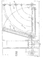
- the numeral 1 indicates the basic frame of the machine according to the invention comprising on the front an appendix formed by two L shaped elements, of which only one is shown and indicated in 2, and each showing the end of a long and short extension both being integral respectively with a corresponding mounting pillar and base girder of basic frame 1 itself.
- each of said L shaped elements On the front end of each of said L shaped elements a supporting member 3 of two bearing and supporting wheels 4 of a respective end of shaft 5 of a spool 6 onto which the tubular material in sheet for continuous formation of sacks, which in the present example is raffia, is wound, there being provided a breaking device 7 for every two wheels 4 which is actuated by a double action pneumatic cylinder 8.
- tubular raffia material during its unwinding travel is first of all guided downwards to ensure good adhesion between shaft 5 of spool 6 and the pairs of bearing wheels 4 and to this end it is successively caused to pass over rollers 10, 11 and 12 of which the first and third are pivotally fixed to the base . of frame 1, while the second is free to move from the bottom on up and viceversa along appropriate vertical guides 13 in order to avoid irregular unwinding of tubular material 9 which from fixed roller 10 reaches free roller 11 and continues on, from the latter, towards the other fixed roller 12 through rollers 14 and 15, respectively, which are pivotally - fixed in coincidence with the upper ends of guides 13.
- tubular material 9 travels on upwards in order to pass, by means of roller 16, through ink dispensing cylinders on a conventional printing device, generally indicated in 17, description of which is omitted as known, which permits descriptions and desired identification designs to be formed and printed on the sacks.
- tubular material 9 travels on upwards and then downwards onto roller 18, so as to allow the ink of the print to dry out, and then again upwards onto roller 19 to roller 20 from which it passes through traction cylinders 21 actuated, through a chain transmission, by a gearbox 22, said cylinders 21 provide upstream unwinding of the tubular material 9 from spool 6 pulling it along the previously described path and, downstream, provide for making it proceed to a first face plane 23 on which two parallel transversal and spaced apertures are formed, while at the same time an automatic measuring device, such as an electronic impulse counter (not shown), determins the preset length of the sack to be formed and according to such length tubular material 9 undergoes a cutting operation along a line which is transversal and perpendicular to the axis of the sack itself.
- an automatic measuring device such as an electronic impulse counter (not shown)
- a cutting device 24 is provided (see Fig. 2) which through appropriate means is brought to high temperature.
- the cutting operation under such conditions causes the ends of the edges of the tubular raffia material to be sealed both downstream and upstream of the cutting operation that is in coincidence of the bottom of the sack already cut to size and respectively of the opening of the following sack still to be cut.
- a laminar element 27 (see Figs. 2 and 3) apt to perform a folding over operation on the bottom of the sack, previously cut to size, in cooperation with a certain number of flat jaw devices 28 (see Figs. 3, 4 and 5) placed in a spaced relationship on a supporting bar. Said folding over operation of the bottom of the sack being absolutely necessary in raffia and jute sacks, and the like, in order to obtain a definite closing of the sack's bottom itself.
- the laminar element disengages allowing said supporting bar to be first raised upwards under the action of pneumatic cylinder 29' and then undergo under the action of double action pneumatic cylinder 29, by 90° counterclockwise so as to cause turning upside down of the folded over bottom of the sack, from a perpendicular direction to a direction parallel to the sense of the sack's advancing direction, thus placing it beyond its corresponding side edge (see Fig. 6).
- the folded over bottom of the sack, so positioned, is gripped between the fixed part and movable part, the latter being driven by a pneumatic double action cylinder 32, of chain driven conveyor arm 30 (see Fig. 5) which is supported at one end, by a small column 32 and is actuated through motor 33.
- Second fixed face plane 36 for transferring from the first to the second conveying belt 34 and respectively 37, which operate independently from each other, serves the purpose of filling in on any dead time occurring in preceding or following operating phases.
- the second conveyor belt 37 on which now the formed sack lies provides for forwarding of the sack towards the exit end of the apparatus in coincidence with which are situated two upper and lower suction hoods 38 and 39 which are connected through respective tubes 40 and 41 to a suction device 42 equipped with an interception valve 43 and actuated by motor 44.
- the first gripping device 48 undergoes a downwards rotation around fulcrum 49 and still under the action of pneumatic cylinder 47 till it reaches the open prongs of a second gripping device 51 (see Fig. 8) which,under the action of the associated pneumatic cylinder 50', close thus gripping the sack while the prongs of the first gripping device 48 open due to the inverse action of pneumatic cylinder 50 thus allowing it to return to its starting position.
- the second gripping device 51 which holds the sack, performs a 90° rotation downwards around fulcrum 52 under the drive of a further pneumatic double action cylinder (not shown) till it positions horizontally, and in such position it is brought underneath the sack holding device 53 of the loading port through the action of supporting rod 54 which slides towards the outside.
- the sack holding device 52 grips the sack which is held by the second gripping device 51 allowing the latter to return to its starting position once its prongs open again.
- wall 55 of sack holding device 53 which is in front of the second gripping device 51, as in opposition to what is provided for in known conventional sack holding devices, is made so as to be able to slide upwards and downwards under the action of double action pneumatic cylinder (not shown) so that in the upper position it allows the second gripping device 51 to follow its straight path till it reaches the position underneath the sack holding machine 52 and then movable wall 55 is once again brought downwards thus resetting the usual operating procedure of the sack holding device 52 itself.
- Fig. 2 shows the heated cutting device 24, the device for separating the edges.of the opening of the sack comprising the series of steel brushes 25 and 26 and the device for folding over the bottom of the cut sack comprising tubular element 27.
- the heated cutting device 24 comprises a blade 56 and a counter-blade 57 respectively above and beneath the first face plane 23 in coicidence of the first aperture of the latter.
- Blade 56 vertically fixed to the free end of a support 58 the other end of which is integral with a system of movable frames to be described later, is associated with an electric resistance apt to heat it to a temperature of 220 - 250°C for achieving best results in cutting of the tubular material 9 of raffia or the like.
- the device for separating the edges of the aperture of the sack comprises a certain number of upper steel brushes 25 and lower steel brushes 26, placed in an equally distanced relation according to a perpendicular alignement with respect to face plane 23, the upper series of brushes 25 being supported by a sprung and adjustable system 59 while the series of lower brushes 26 is supported in a movable way by said system of moving frames to which, the lower end of support 60 of laminar element 27 for folding over the bottom of the cut sack situated in coincidence with the second aperture of face plane 23 is also fixed.
- the moving frame system has been obtained by placing its fulcrum, as shown in 62 of Fig. 1, at one end of two heavy frames of which one, 63, is external and the other, 64, internal with the addition of a third frame 65 which has its fulcrum on the other end of the internal frame 64 in order to always be in a vertical position while the free end of the piston rod of the double action pneumatic cylinder 65 uses the other free end of external frame 63 as fulcrum.
- Said movements cause the raising of blade 56, the support 58 of which is integral with internal frame 64, so as to perform, in a position with the counterblade 57, the operation of heat cutting of tubular material 9 of raffia through the first opening on face plane 23 and at the same time raising of the series of lower brushes 26 till they are brought, through appropriate openings (not shown) formed on face plane 23 in contact with the corresponding series of upper brushes 25 with the interposition of the free terminal part of the tubular material upstream of the cutting just performed thus forming the opening of the next sack after the one already cut and which due to the heat cutting operation will appear to be sealed.
- laminar element 27 for the folding over of the bottom of the sack just previously cut to size is best illustrated in Fig. 3 wherein it may be seen that said component engages in its upwards movement the cut sack, partially shown and indicated in 72, at a short distance from its rear end and carries the folded over bottom of the sack in coincidence of a series of gripping devices placed in a spaced relation on a movable supporting bar perpendicular to the direction of advancement of the sack in the starting position.
- Each gripping device comprises a fixed member 74 and a moving member 75 actuated by a double action pneumatic cylinder 76, the device having, in coincidence of the moving member's free end, a helical return spring 77.
- member 75 due to the withdrawal of the rod of pneumatic piston 76, closes onto member 74 determining, at the same time, the extension of return spring 77.
- the laminar element 27 is withdrawn from between closed members 74 and 75 and it moves downwards, due to a similar movement of said associated external frame 63.
- this element does not have a continuous surface but empty spaces are formed on it which flank the entrance portions between members 74 and 75 so as to reduce its dimensions to a minimum indispensable for carrying out the assigned job, as can be better seen in the front partial elevated view on the right of Fig. 3.
- Fig. 4 shows the rotating movement of bar 78 which carries the gripping devices 28 apt to perform overturning of the gripped sack, said overturning being already described in the preliminary general description of the machine according to the invention with reference to Fig. 1.
- Said overturning of the gripped bottom of the sack is done by causing a rotation by 90°, in a counterclockwise direction, of bar 78 shown in broken lines in the starting position and in full lines in the final position. Said rotation takes place through withdrawal of the rod of the piston of the double action pneumatic cylinder 29 which is journalled on an end of a lever 79 the other end of which is fixed to pivot 80 integral with a terminal part of bar 78 itself.
- Fig. 5 a subsequent operative phase of the apparatus according to the invention is shown, which provides . stitching of the folded over and turned over bottom of the sack.
- conveying arm 30 carries the folded over and overturned bottom of the sack to the stitching machine 35 which provides for sewing a seam in the sack, the sack with the sewed bottom still in the overturned position being then transferred to the second conveyor belt 37, after passing the second fixed plane 36, for forwarding towards the exit of the machine as is clearly visible in Fig. 6.
- the sack, completely formed, through the second conveyor belt 37 arrives to, the exit end of the machine where the suction hoods 38 and 39 open the opening of the sack itself so that it may be gripped by the first gripping device 48 and then transferred onto the second gripping device 51 which forwards the sack to the sack holding device 52 of the loading station 53, as previously described.
- the gripping device 48 in a closed position and 51 in an open position are shown in detail in Fig. 8 wherein it is also possible to clearly observe the rotation movement of the first over the second for said transferring of the sack from one to the other.
- each of said gripping devices comprises two parallel and spaced arms, of which only one is shown and indicated in 90, each of which is integral in coincidence of an end with an appendix 91 the free end of which is journalled on a common rotating shaft 92 which in the general description of the apparatus with reference to Fig. 1 corresponds to fulcrum points 49 and respectively 52 of the first and second gripping devices 48 and 51.
- each arm 90 On the terminal free part of each arm 90 are fixed in a parallel and spaced relation first and second shorter fixed arms 93 and 94 and between these are first and second journalled prongs 95 and 96 respectively the fulcrum part of each of which is integral with an appendix 97 and 98 respectively, the center, lines of which form an angle of 90° with the associated centerlines of prongs 95 and 96 the ends of which are connected rotatably through pivot 99.
- the rod of the second prong 96 extends beyond the fulcrum point on its respective arm 90 till it connects with the end of the rod of the piston of a double action pneumatic cylinder 100, already indicated respectively in 50 and 50' in the first and second gripping device 48 and 51 in the general description of the apparatus with reference to Fig. 1, said cylinder is being supported at the base by a support 101 integral with its associated arm 90.
- the distance between the outside faces of the fixed arms 93 and 94 of the first gripping device is smaller than the distance between the inside faces of the respective fixed arms 93 and 94 of the second gripping device in order to allow for the entrance of the arms of first between the arms of second.
- the apparatus for performing such operations, is provided, as an alternative, with a blade 102 and associated counter-blade 103 and immediately after, with a plate 104 and a counter- plate 105 for heat-sealing which are brought to adequate temperature through appropriate electrical resistances, the operation taking place in the same manner as that of similar components previously described, that is through movement upwards through respective apertures on said first face plane of blade 102 and of plate 104 through said system, of movable internal and external frames 63 and 64 till blade 102 and said plate 104 are brought in contrast respectively with the counter-blade 103 and counter-plate 105.
- the apparatus according to the invention may be conveniently used with a conventional apparatus for feeding prefabricated sacks and in particular with the apparatus described and claimed in patent No. 1035782 assigned to the applicant of this patent in which case said second previously mentioned gripping device for transferring of the sack to the sack holding device of the feeding station could consist of the gripping device provided in said feeding apparatus according to the above mentioned patent.
Landscapes
- Engineering & Computer Science (AREA)
- Mechanical Engineering (AREA)
- Supplying Of Containers To The Packaging Station (AREA)
- Making Paper Articles (AREA)
Applications Claiming Priority (2)
| Application Number | Priority Date | Filing Date | Title |
|---|---|---|---|
| IT48195/80A IT1193771B (it) | 1980-03-18 | 1980-03-18 | Macchina per la formazione continua di sacchi ed il loro inoltro ad una bocca di riempimento |
| IT4819580 | 1980-03-18 |
Publications (2)
| Publication Number | Publication Date |
|---|---|
| EP0036400A2 true EP0036400A2 (de) | 1981-09-23 |
| EP0036400A3 EP0036400A3 (de) | 1982-07-28 |
Family
ID=11265137
Family Applications (1)
| Application Number | Title | Priority Date | Filing Date |
|---|---|---|---|
| EP81830045A Withdrawn EP0036400A3 (de) | 1980-03-18 | 1981-03-17 | Apparat zum kontinuierlichen Herstellen und Füllen von Beuteln |
Country Status (2)
| Country | Link |
|---|---|
| EP (1) | EP0036400A3 (de) |
| IT (1) | IT1193771B (de) |
Cited By (4)
| Publication number | Priority date | Publication date | Assignee | Title |
|---|---|---|---|---|
| EP0974517A1 (de) * | 1998-07-24 | 2000-01-26 | CONCETTI S.p.A. | Maschine zum Formen, Füllen und Versiegeln von Beuteln |
| RU2186007C2 (ru) * | 2000-05-23 | 2002-07-27 | Открытое акционерное общество "Татнефть" | Стеллаж для затаривания битума в мешки |
| CN108909026A (zh) * | 2018-06-01 | 2018-11-30 | 常熟市泰宁医疗器材有限责任公司 | 废液袋自动组装机 |
| CN109229637A (zh) * | 2018-10-30 | 2019-01-18 | 四川成创包装机械科技有限公司 | 一种新型三联袋自动包装机 |
Family Cites Families (6)
| Publication number | Priority date | Publication date | Assignee | Title |
|---|---|---|---|---|
| US2721077A (en) * | 1951-07-21 | 1955-10-18 | Forgrove Mach | Feeding of wrapping materials to wrapping machines |
| GB718311A (en) * | 1952-05-16 | 1954-11-10 | Alfons Muller | Improvements in methods of and apparatus for cutting materials |
| GB1283526A (en) * | 1968-09-25 | 1972-07-26 | Percy Sheard | Apparatus for cutting synthetic plastics material webs |
| FR2051125A5 (en) * | 1970-06-12 | 1971-04-02 | Barthelemy Jean | Semi-automatic cutting or welding of synth- - etic fabrics for bags |
| US4031818A (en) * | 1974-10-16 | 1977-06-28 | Gaf Corporation | Apparatus for preparing sealed envelope units with messages |
| DE2459725A1 (de) * | 1974-12-18 | 1976-07-01 | Librawerk Pelz & Nagel Kg | Vorrichtung zum beschicken einer beutel- und sackfuelleinrichtung |
-
1980
- 1980-03-18 IT IT48195/80A patent/IT1193771B/it active
-
1981
- 1981-03-17 EP EP81830045A patent/EP0036400A3/de not_active Withdrawn
Cited By (4)
| Publication number | Priority date | Publication date | Assignee | Title |
|---|---|---|---|---|
| EP0974517A1 (de) * | 1998-07-24 | 2000-01-26 | CONCETTI S.p.A. | Maschine zum Formen, Füllen und Versiegeln von Beuteln |
| RU2186007C2 (ru) * | 2000-05-23 | 2002-07-27 | Открытое акционерное общество "Татнефть" | Стеллаж для затаривания битума в мешки |
| CN108909026A (zh) * | 2018-06-01 | 2018-11-30 | 常熟市泰宁医疗器材有限责任公司 | 废液袋自动组装机 |
| CN109229637A (zh) * | 2018-10-30 | 2019-01-18 | 四川成创包装机械科技有限公司 | 一种新型三联袋自动包装机 |
Also Published As
| Publication number | Publication date |
|---|---|
| EP0036400A3 (de) | 1982-07-28 |
| IT1193771B (it) | 1988-08-24 |
| IT8048195A0 (it) | 1980-03-18 |
Similar Documents
| Publication | Publication Date | Title |
|---|---|---|
| US4322932A (en) | Bag filling and handling apparatus | |
| US5771667A (en) | Bag filling, closing, and sealing machine | |
| US4432186A (en) | Automatic bag hanger | |
| US6295790B1 (en) | Compact bag filling machine | |
| JP3839222B2 (ja) | 袋を製造、充填、シールする装置 | |
| US6672038B2 (en) | Bag manipulating method and assembly for a bag filling station | |
| US3673759A (en) | Bag hanger apparatus | |
| US4078358A (en) | Bag-hanging and bag-filling machines adapted for synchronous and independent operation and method of using same | |
| US4018031A (en) | Article packaging machine | |
| US4873815A (en) | Apparatus for filling and closing sacks which are open at one end | |
| US5448879A (en) | Automatic machine for forming, filling and sealing sacks and the like | |
| US4115978A (en) | Apparatus for automatically filling and closing sacks | |
| EP0413431B1 (de) | Vorrichtung zum Verpacken | |
| US3877562A (en) | Article packaging machine | |
| US6658821B2 (en) | Bag loading method and assembly for a bag filling station | |
| US3287879A (en) | Bag dispensing, transporting and positioning apparatus | |
| US5483786A (en) | Apparatus for packaging articles | |
| EP0036400A2 (de) | Apparat zum kontinuierlichen Herstellen und Füllen von Beuteln | |
| US3423903A (en) | Bag positioning apparatus | |
| JPS58112905A (ja) | 袋形式パツケ−ジを製造するための方法及び装置 | |
| US4548243A (en) | Apparatus for automatically placing bags | |
| US3469367A (en) | Bag feeding and filling apparatus | |
| US4580391A (en) | Apparatus for infolding laterally protruding wings of a filled sack onto adhesive strips provided on the top of the sack | |
| US6351926B1 (en) | Packaging system | |
| US5282351A (en) | Method for making, filling and sealing sacks |
Legal Events
| Date | Code | Title | Description |
|---|---|---|---|
| PUAI | Public reference made under article 153(3) epc to a published international application that has entered the european phase |
Free format text: ORIGINAL CODE: 0009012 |
|
| AK | Designated contracting states |
Designated state(s): AT BE CH DE FR GB LU NL SE |
|
| PUAL | Search report despatched |
Free format text: ORIGINAL CODE: 0009013 |
|
| AK | Designated contracting states |
Designated state(s): AT BE CH DE FR GB LU NL SE |
|
| STAA | Information on the status of an ep patent application or granted ep patent |
Free format text: STATUS: THE APPLICATION IS DEEMED TO BE WITHDRAWN |
|
| 18D | Application deemed to be withdrawn |
Effective date: 19830517 |
|
| RIN1 | Information on inventor provided before grant (corrected) |
Inventor name: CONCETTI, TEODORO |