EP0036432A1 - Contacteur, en particulier un contacteur de puissance ou de commande ou de mise en marche - Google Patents
Contacteur, en particulier un contacteur de puissance ou de commande ou de mise en marche Download PDFInfo
- Publication number
- EP0036432A1 EP0036432A1 EP80101314A EP80101314A EP0036432A1 EP 0036432 A1 EP0036432 A1 EP 0036432A1 EP 80101314 A EP80101314 A EP 80101314A EP 80101314 A EP80101314 A EP 80101314A EP 0036432 A1 EP0036432 A1 EP 0036432A1
- Authority
- EP
- European Patent Office
- Prior art keywords
- contact
- contactor
- switch
- bracket
- actuated
- Prior art date
- Legal status (The legal status is an assumption and is not a legal conclusion. Google has not performed a legal analysis and makes no representation as to the accuracy of the status listed.)
- Granted
Links
- 239000007858 starting material Substances 0.000 title claims abstract description 4
- 230000006835 compression Effects 0.000 claims description 3
- 238000007906 compression Methods 0.000 claims description 3
- 238000010276 construction Methods 0.000 abstract description 5
- 230000000994 depressogenic effect Effects 0.000 abstract 1
- 238000010586 diagram Methods 0.000 description 3
- 230000000694 effects Effects 0.000 description 2
- 238000004519 manufacturing process Methods 0.000 description 2
- 238000000034 method Methods 0.000 description 2
- 238000005516 engineering process Methods 0.000 description 1
- 230000035945 sensitivity Effects 0.000 description 1
- 210000002105 tongue Anatomy 0.000 description 1
- 238000011144 upstream manufacturing Methods 0.000 description 1
Images



Classifications
-
- H—ELECTRICITY
- H01—ELECTRIC ELEMENTS
- H01H—ELECTRIC SWITCHES; RELAYS; SELECTORS; EMERGENCY PROTECTIVE DEVICES
- H01H50/00—Details of electromagnetic relays
- H01H50/54—Contact arrangements
- H01H50/546—Contact arrangements for contactors having bridging contacts
Definitions
- the invention relates to a contactor, in particular a power or control contactor or starter contactor, with a contact system accommodated in a housing and a magnet system actuating the contact system, the contact system contact rails with fixed contact pieces and actuatable as a break contact and / or by means of a common bridge girder. or closer bridges with movable contact pieces, each bridge and the associated contact rails are housed in a switching chamber, and wherein a switch-on contact is provided with self-holding.
- These types of contactors can be used both as single contactors and in combinations of contactors.
- Contactors of the aforementioned type are known in practice in various types. These shooters generally have a plunger which can be actuated from the outside, for example by hand using a push button, and which is on a common bridge girder acts and causes this to move, so that when the voltage is applied to the contactor, a certain switching process can be carried out with the provided break contacts and / or make contacts. After releasing the push button, the contactor returns to the original position and the switching process is finished. In practice, however, it is necessary to hold a switching operation for a longer period of time without the push button being constantly pressed by hand during this time. For this purpose, a special switch-on contact is provided and it has been proposed to use a normally open contact of the contactor for the self-holding of the contactor. Another separate switch-off contact is provided to switch off the contactor.
- the invention has for its object to provide a contactor in which the construction costs and space requirements are significantly reduced and simple wiring is possible.
- a contact bracket for switching on Contact with the contactor is structurally integrated, can be actuated from the outside by means of an actuating element and interacts with the common bridge girder.
- the contact path of the integrated switch-on contact contains three functions, namely switching on the contactor, simultaneously with the same switch-on contact the latching device's self-holding and finally the usability of this switch-on contact with the appropriate circuit arrangement for normal closing as with another normal NO contact the shooter.
- An advantageous embodiment of the invention is that a further contact bracket is provided for as a switch-off contact in a structural unit with the contact bracket of the switch-on contact, and that the contact bracket of the switch-off contact can be actuated from the outside by means of an actuating element.
- the further separate switch housing of the switch-off contact according to the prior art is avoided and the wiring is further simplified.
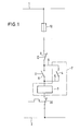
- Figure 1 shows a simplified circuit diagram for a contactor, which is connected to a power network with lines 1 and 2. If the main switch 20 is closed, the contactor 3 can only pull in when the switch-on contact 8 is also actuated. A further contact 4 is connected in parallel to this switch-on contact 8 via lines 5, 6, which can be designed as a contact of the contactor 3 and also closes after the contactor has closed and keeps the contactor energized even when the switch-on contact 8 is opened again.
- the dash-dotted line 7 indicates that the contact 4 is one of the contacts of the contact system of the contactor 3.
- a switch-off contact 9 is used to switch off the contactor, which interrupts the circuit and allows the contactor to drop out again.
- a conventional fuse is also designated by reference number 10. According to the state The technology, as explained at the beginning, accommodates the two contacts 8 and 9 as switch-on contacts and switch-off contacts in separate switch housings.
- a contact bracket of the switch-on contact with the contactor is structurally integrated, can be actuated from the outside by means of an actuating element and is designed to cooperate with a common bridge girder for self-holding.
- An exemplary embodiment of this basic idea of the invention is shown in FIGS. 2 to 5 in different switching positions.
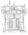
- a magnet system with a magnetic core 36, a coil 37 and with a magnet armature 45 is located in the simplified housing of the contactor 3.
- a common bridge support 38 is connected to the magnet armature and is explained in more detail below with reference to FIGS. 11 and 12.
- In the upper part of the contactor housing there is a switching chamber 35, in which a contact bracket 39 for the switch-on contact and a contact bracket 41 for the switch-off contact are arranged.
- the contact bracket 41 is provided in a structural unit with the contact bracket 39 of the switch-on contact.
- the contact bracket of the on and off contacts with associated fixed contact rails 40 and 42 are housed in the common switching chamber 35.
- the contact clips are designed as U-shaped spring clips, which have one end 39b and 41b are attached to the contact rails 40 and 42. At their other end, the spring clips carry overlapping movable contact pieces 39a and 41a.
- the spring clip 39 of the closing contact engages in an opening 38a of the bridge girder 38.
- the contact bracket 39 can be actuated by an actuating element 43 or a push button, while a further actuating element 44 or another push button is provided for actuating the contact bracket 41 of the switch-off contact.
- the operation of the above-mentioned contactor is essentially as follows. In the rest position, the contact brackets 39, 41 of the switch-on and switch-off contacts and the actuating elements 43, 44 or push buttons are in the position shown in FIG. 2, the movable contact pieces 39a and 41a being spaced apart from one another. When actuating the actuating element 43 from the outside, the free leg of the U-shaped spring clip 39 of the switch-on contact is moved downward, so that the contact piece 39a comes into contact with the contact piece 41a, as shown in FIG. 3. This causes the contactor to switch on.
- the construction explained above has essentially four functions, namely switching on, switching the contactor self-holding, switching off and also using the integrated contact device for normal closing, such as those explained below with reference to FIGS. 11 and 12 Bridge or NO contacts. It is understood that in the latter case the actuators 43 and 44 are not actuated.
- a further advantage of the exemplary embodiment according to FIGS. 2 to 5 is that the switching chamber 35 is accommodated in the contactor housing in accordance with the other switching chambers 12d (FIG. 11), which brings about a considerable simplification of production.
- Figure 6 shows another embodiment of a contactor, which is constructed similar to that of Figures 2 to 5, so that the same reference numerals have been used for parts acting in the same way.
- the U-shaped spring clips 46, 47 of the switch-on contact on the one hand and the switch-off contact on the other hand are completely identical or symmetrical, which also applies to the fixed contact rails 40, 42.
- the magnet system Inside the housing part 11, the magnet system is housed, which consists of a coil 16 with connecting lines 17 and connectors 18, 19 and a magnetic core 34 and a movable armature 31.
- the coil 16 and the magnetic core can be fastened with the aid of a Bracket 14 can only be done by simply inserting it with a clamping effect.
- tongues 11c are provided which cooperate with recesses and locking points 12b of the housing part 12.
- tongue-like projections 12c are also provided, which engage in recesses with locking points lld of the housing part 11.
- the housing part 12 contains a contact system.
- four switching chambers 12d are provided in parallel next to each other within the predetermined width between the two side surfaces 12a.
- One of these switching chambers preferably the switching chamber 12f shown in FIG. 11 near the front edge, is designed in accordance with the switching chamber 35 explained above.
- the interrupters as such are essentially designed as U-shaped grooves with open end faces. Dabe- open the U-shaped channels the side away from the mounting level.
- In the switching chambers 12d there are two contact rails 24 with fixed contact pieces 24a, which are held by inserting in guides 26, 27 of the housing part 12 and in a substantially rectangular frame 30 by contact connection screws 21.
- the contact connection screws 21 simultaneously hold the electrical connection lines 28.
- a bridge 25 with movable contact pieces 25a cooperates with the two contact rails 24 in the switching chambers 12d.
- the bridge 25 is taken out together with the contact spring 33 from the opening 38c of the common for all the bridges bridge carrier 38 and to below 180 0 into the opening 38e reinstated.
- the common bridge support 38 consists essentially of a plate, one end of which is connected to the armature 31 of the magnet system.
- compression springs 32 are provided which, when the coil 16 is not switched on, press the armature 31 and the common bridge support 38 back into the rest position shown.
- the bridge points at the end remote from the mounting level Carrier 38 has a projection 38d which projects through an opening 13d of the housing part 13 serving as a cover.
- the housing part 13 covers the contact system in the housing part 12. In this housing part two rows of holes 13b are provided, through which a screwdriver can be inserted, which is simultaneously guided by the wall of the hole concerned and which allows the contact terminal screws 21 and 22 to be tightened in a freely accessible manner.
- a further channel-like space 12e is provided within the predetermined width between the side walls 12a, in which the two connection screws 22 for the coil of the magnet system are accommodated.
- the housing part 13 can also be attached to the housing part 12 by sliding and clamping.
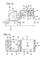
- FIGS. 13 and 14 show a further exemplary embodiment of the invention, namely a contactor 53 with contact connection screws 56, 57 and further connection screws 58 and 67 for the coil and with an integrated switching chamber 54, which essentially corresponds to the configuration according to FIGS 5 matches.
- the same reference numerals have therefore been used for parts with the same effect.
- the common bridge girder has an extension 55 which protrudes outwards from the housing and can be used as a push button. Furthermore, actuating elements 43, 44 are again provided.
- the contactor 53 is a motor protection device 59 is connected upstream, which is connected to the contactor 53 via electrical lines 60 and 61.
- the motor protection device has an adjusting lever 62 in relation to a scale 63, so that the trigger sensitivity of this device can be set.
- This motor protection device also has contact connection screws 64, 65 and 66.
- pusher buttons 68 and 69 are provided, the pusher button 68 also being usable as a switch-off button since it acts on a switch-off contact. In this embodiment of the combined device, the actuating element 44 or the push button 68 can thus be actuated either to switch it off. Under certain circumstances, the actuating element 44 can then also be omitted.
- FIG. 15 shows a further exemplary embodiment, which essentially corresponds to that according to FIG. 13, but here the movable contact bracket 70 of the switch-on contact is designed as a C-shaped spring bracket with two resilient, movable contact pieces 70a, 70b. These contact pieces work together with fixed contact pieces 71a, 72a, of contact rails 71, 72.
- the C-shaped spring clip 70 is held in an opening of the actuating element 74 or the common bridge girder by means of a compression spring 73.
- a fork-shaped tappet 75 the C-shaped spring clip 70 can be pressed in the direction of the fixed contact rails 71, 72 and the switching on can be carried out. Switching off can take place in accordance with the exemplary embodiment according to FIGS. 13 and 14 by means of a plunger 76 via a pushbutton 68 of the motor protection switch 59.
Landscapes
- Electromagnetism (AREA)
- Physics & Mathematics (AREA)
- Push-Button Switches (AREA)
- Control Of Direct Current Motors (AREA)
- Valve Device For Special Equipments (AREA)
- Switch Cases, Indication, And Locking (AREA)
- Relay Circuits (AREA)
- Control Of Eletrric Generators (AREA)
- Diaphragms For Electromechanical Transducers (AREA)
- Alarm Systems (AREA)
- Burglar Alarm Systems (AREA)
- Switches With Compound Operations (AREA)
- Lock And Its Accessories (AREA)
Priority Applications (10)
| Application Number | Priority Date | Filing Date | Title |
|---|---|---|---|
| EP80101314A EP0036432B2 (fr) | 1980-03-13 | 1980-03-13 | Contacteur, en particulier un contacteur de puissance ou de commande ou de mise en marche |
| AT80101314T ATE10886T1 (de) | 1980-03-13 | 1980-03-13 | Schuetz, insbesondere leistungs- oder steueroder starter-schuetz. |
| DE8080101314T DE3069816D1 (en) | 1980-03-13 | 1980-03-13 | Contactor, particularly a power or control or starter contactor |
| DK175280A DK147473C (da) | 1980-03-13 | 1980-04-24 | Elektrisk sikring eller vaern med et i et hus anbragt magnetsystem, der betjener et kontaktsystem |
| ES492296A ES8101311A1 (es) | 1980-03-13 | 1980-06-10 | Perfeccionamientos en contactores, especialmente contactoresde potencia o de control o bien contactores arrancadores |
| NO803242A NO154858C (no) | 1980-03-13 | 1980-10-30 | Kontaktor, saerlig effekt- eller styre- eller startkontaktor. |
| BR8101424A BR8101424A (pt) | 1980-03-13 | 1981-03-11 | Rele, em particular rele de potencia, rele de comando ou rele de arranque |
| AU68309/81A AU533921B2 (en) | 1980-03-13 | 1981-03-12 | Switch |
| US06/242,853 US4337447A (en) | 1980-03-13 | 1981-03-12 | Switch |
| CA000372895A CA1168278A (fr) | 1980-03-13 | 1981-03-12 | Contracteur electrique a calage magnetique |
Applications Claiming Priority (1)
| Application Number | Priority Date | Filing Date | Title |
|---|---|---|---|
| EP80101314A EP0036432B2 (fr) | 1980-03-13 | 1980-03-13 | Contacteur, en particulier un contacteur de puissance ou de commande ou de mise en marche |
Publications (3)
| Publication Number | Publication Date |
|---|---|
| EP0036432A1 true EP0036432A1 (fr) | 1981-09-30 |
| EP0036432B1 EP0036432B1 (fr) | 1984-12-19 |
| EP0036432B2 EP0036432B2 (fr) | 1988-10-12 |
Family
ID=8186631
Family Applications (1)
| Application Number | Title | Priority Date | Filing Date |
|---|---|---|---|
| EP80101314A Expired EP0036432B2 (fr) | 1980-03-13 | 1980-03-13 | Contacteur, en particulier un contacteur de puissance ou de commande ou de mise en marche |
Country Status (10)
| Country | Link |
|---|---|
| US (1) | US4337447A (fr) |
| EP (1) | EP0036432B2 (fr) |
| AT (1) | ATE10886T1 (fr) |
| AU (1) | AU533921B2 (fr) |
| BR (1) | BR8101424A (fr) |
| CA (1) | CA1168278A (fr) |
| DE (1) | DE3069816D1 (fr) |
| DK (1) | DK147473C (fr) |
| ES (1) | ES8101311A1 (fr) |
| NO (1) | NO154858C (fr) |
Families Citing this family (9)
| Publication number | Priority date | Publication date | Assignee | Title |
|---|---|---|---|---|
| DE3402741C2 (de) * | 1984-01-27 | 1986-10-02 | TRIPUS-Kunststoffteile GmbH, 8870 Günzburg | Vorrichtung zum Ein- und Ausschalten elektrischer Geräte |
| SE445505B (sv) * | 1984-11-13 | 1986-06-23 | Tocksfors Verkstads Ab | Elektriskt rele |
| DE8802393U1 (de) * | 1988-02-24 | 1988-05-11 | Lindner GmbH Fabrik elektrischer Lampen und Apparate, 96052 Bamberg | Aus Haupt- und Hilfsschalter bestehende Schalterkombination |
| US5144516A (en) * | 1991-02-04 | 1992-09-01 | Wing Shing Products Company, Ltd. | Leakage current circuit interrupter device |
| US5933063A (en) * | 1997-07-21 | 1999-08-03 | Rototech Electrical Components, Inc. | Ground fault circuit interrupter |
| CN101281832B (zh) * | 2007-04-05 | 2010-07-21 | 浙江正泰电器股份有限公司 | 接触器的绝缘保护结构 |
| US7772945B2 (en) * | 2007-10-11 | 2010-08-10 | Jackson Edmonds, Llc | Electrical switching device |
| US20110037543A1 (en) * | 2007-10-11 | 2011-02-17 | Dale Walter Lange | Electrical switching device |
| JP6857092B2 (ja) * | 2017-06-28 | 2021-04-14 | 富士通コンポーネント株式会社 | 電磁継電器 |
Citations (4)
| Publication number | Priority date | Publication date | Assignee | Title |
|---|---|---|---|---|
| DE1813182U (de) * | 1960-03-26 | 1960-06-15 | Continental Elektro Ind Ag | Schaltschuetz mit selbsthaltekontakt. |
| DE1825204U (de) * | 1959-06-29 | 1961-01-19 | Franz Morschel | Schaltschuetz. |
| DE1167948B (de) * | 1959-11-05 | 1964-04-16 | Busch Jaeger Duerener Metall | Elektromagnetisches Schuetz |
| GB1273255A (en) * | 1969-09-11 | 1972-05-03 | Midland Electric Mfg Co Ltd | Electromagnetic switches |
Family Cites Families (2)
| Publication number | Priority date | Publication date | Assignee | Title |
|---|---|---|---|---|
| US3808567A (en) * | 1973-01-30 | 1974-04-30 | A Maier | Circuit breaker with improved resettable latch and trip means |
| US3852544A (en) * | 1973-09-17 | 1974-12-03 | Westinghouse Electric Corp | Fluid operated electrical contactor with contact coolant means |
-
1980
- 1980-03-13 EP EP80101314A patent/EP0036432B2/fr not_active Expired
- 1980-03-13 DE DE8080101314T patent/DE3069816D1/de not_active Expired
- 1980-03-13 AT AT80101314T patent/ATE10886T1/de active
- 1980-04-24 DK DK175280A patent/DK147473C/da not_active IP Right Cessation
- 1980-06-10 ES ES492296A patent/ES8101311A1/es not_active Expired
- 1980-10-30 NO NO803242A patent/NO154858C/no unknown
-
1981
- 1981-03-11 BR BR8101424A patent/BR8101424A/pt unknown
- 1981-03-12 AU AU68309/81A patent/AU533921B2/en not_active Ceased
- 1981-03-12 CA CA000372895A patent/CA1168278A/fr not_active Expired
- 1981-03-12 US US06/242,853 patent/US4337447A/en not_active Expired - Fee Related
Patent Citations (4)
| Publication number | Priority date | Publication date | Assignee | Title |
|---|---|---|---|---|
| DE1825204U (de) * | 1959-06-29 | 1961-01-19 | Franz Morschel | Schaltschuetz. |
| DE1167948B (de) * | 1959-11-05 | 1964-04-16 | Busch Jaeger Duerener Metall | Elektromagnetisches Schuetz |
| DE1813182U (de) * | 1960-03-26 | 1960-06-15 | Continental Elektro Ind Ag | Schaltschuetz mit selbsthaltekontakt. |
| GB1273255A (en) * | 1969-09-11 | 1972-05-03 | Midland Electric Mfg Co Ltd | Electromagnetic switches |
Also Published As
| Publication number | Publication date |
|---|---|
| BR8101424A (pt) | 1981-09-15 |
| AU533921B2 (en) | 1983-12-15 |
| NO154858B (no) | 1986-09-22 |
| EP0036432B1 (fr) | 1984-12-19 |
| ATE10886T1 (de) | 1985-01-15 |
| ES492296A0 (es) | 1980-12-16 |
| US4337447A (en) | 1982-06-29 |
| DK175280A (da) | 1981-09-14 |
| DK147473C (da) | 1985-03-11 |
| DE3069816D1 (en) | 1985-01-31 |
| AU6830981A (en) | 1981-09-17 |
| NO803242L (no) | 1981-09-14 |
| ES8101311A1 (es) | 1980-12-16 |
| NO154858C (no) | 1987-01-07 |
| EP0036432B2 (fr) | 1988-10-12 |
| DK147473B (da) | 1984-08-20 |
| CA1168278A (fr) | 1984-05-29 |
Similar Documents
| Publication | Publication Date | Title |
|---|---|---|
| EP0036027B1 (fr) | Contacteur éléctromagnétique | |
| DE3874168T2 (de) | Fernbetaetigter ein-/aus-schutzschalter. | |
| DE69110409T2 (de) | Schutzschalter. | |
| EP0185107B1 (fr) | Disjoncteur de protection pour moteurs | |
| EP0237607A1 (fr) | Contacteur | |
| EP0033841B1 (fr) | Relais | |
| DE9001448U1 (de) | Schaltvorrichtung mit geschützten Unterbrechern | |
| DE19818058C2 (de) | Schaltgerät mit einer Schaltkammer-Baugruppe | |
| EP0287752B1 (fr) | Interrupteur électromagnétique avec entraînement électromagnétique | |
| EP0036432B2 (fr) | Contacteur, en particulier un contacteur de puissance ou de commande ou de mise en marche | |
| DE3220040A1 (de) | Elektromagnetisches schaltschuetz | |
| EP0000711A1 (fr) | Contacteur avec bornes de raccordement librement accessibles et disposées dans des plans différents | |
| EP0802552B1 (fr) | Interrupteur électrique à déclenchement par manque de tension | |
| DE7426189U (de) | HilfGeschalter-Anbauteil für Leitungsschutzschalter | |
| DE9403259U1 (de) | Gehäuseaufbau für einen Niederspannungs-Schutzschalter mit Hilfsschalterblock | |
| EP1135784A1 (fr) | Element de contact | |
| EP0243648B1 (fr) | Disjoncteur électrique | |
| DE69215348T2 (de) | Schaltgeräte für elektromagnetische und manuelle Betätigung | |
| DE8433019U1 (de) | Elektromagnetisches Klappankerrelais | |
| DE1084821B (de) | Trennschutzschalter | |
| DE3308437C2 (fr) | ||
| DE2532527A1 (de) | Elektrisches relais | |
| DE69808836T2 (de) | Adapter zur modularen Verbindung elektrischer Geräte zu einem elektrischen Verteilungssystem auf Basis von Schiene | |
| EP0046480B1 (fr) | Dispositif de verrouillage pour boutons de commande des appareils de commutation électriques | |
| DE4002470C2 (de) | Befehlsgerät zum Einbau zwischen zwei parallelflächigen Gehäuseteilen |
Legal Events
| Date | Code | Title | Description |
|---|---|---|---|
| PUAI | Public reference made under article 153(3) epc to a published international application that has entered the european phase |
Free format text: ORIGINAL CODE: 0009012 |
|
| AK | Designated contracting states |
Designated state(s): AT BE CH DE FR GB IT LU NL SE |
|
| 17P | Request for examination filed |
Effective date: 19811022 |
|
| RAP1 | Party data changed (applicant data changed or rights of an application transferred) |
Owner name: SQUARE D STARKSTROM GMBH |
|
| ITF | It: translation for a ep patent filed | ||
| GRAA | (expected) grant |
Free format text: ORIGINAL CODE: 0009210 |
|
| AK | Designated contracting states |
Designated state(s): AT BE CH DE FR GB IT LU NL SE |
|
| REF | Corresponds to: |
Ref document number: 10886 Country of ref document: AT Date of ref document: 19850115 Kind code of ref document: T |
|
| REF | Corresponds to: |
Ref document number: 3069816 Country of ref document: DE Date of ref document: 19850131 |
|
| ET | Fr: translation filed | ||
| PG25 | Lapsed in a contracting state [announced via postgrant information from national office to epo] |
Ref country code: LU Free format text: LAPSE BECAUSE OF NON-PAYMENT OF DUE FEES Effective date: 19850331 |
|
| PLBI | Opposition filed |
Free format text: ORIGINAL CODE: 0009260 |
|
| 26 | Opposition filed |
Opponent name: SIEMENS AKTIENGESELLSCHAFT, BERLIN UND MUENCHEN Effective date: 19850813 |
|
| NLR1 | Nl: opposition has been filed with the epo |
Opponent name: SIEMENS AKTIENGESELLSCHAFT |
|
| PUAH | Patent maintained in amended form |
Free format text: ORIGINAL CODE: 0009272 |
|
| STAA | Information on the status of an ep patent application or granted ep patent |
Free format text: STATUS: PATENT MAINTAINED AS AMENDED |
|
| 27A | Patent maintained in amended form |
Effective date: 19881012 |
|
| AK | Designated contracting states |
Kind code of ref document: B2 Designated state(s): AT BE CH DE FR GB IT LU NL SE |
|
| NLR2 | Nl: decision of opposition | ||
| NLR3 | Nl: receipt of modified translations in the netherlands language after an opposition procedure | ||
| ET3 | Fr: translation filed ** decision concerning opposition | ||
| ITF | It: translation for a ep patent filed | ||
| PGFP | Annual fee paid to national office [announced via postgrant information from national office to epo] |
Ref country code: LU Payment date: 19890315 Year of fee payment: 10 |
|
| PGFP | Annual fee paid to national office [announced via postgrant information from national office to epo] |
Ref country code: SE Payment date: 19890316 Year of fee payment: 10 |
|
| PGFP | Annual fee paid to national office [announced via postgrant information from national office to epo] |
Ref country code: CH Payment date: 19890321 Year of fee payment: 10 |
|
| PGFP | Annual fee paid to national office [announced via postgrant information from national office to epo] |
Ref country code: AT Payment date: 19890328 Year of fee payment: 10 |
|
| ITTA | It: last paid annual fee | ||
| PGFP | Annual fee paid to national office [announced via postgrant information from national office to epo] |
Ref country code: NL Payment date: 19890331 Year of fee payment: 10 Ref country code: GB Payment date: 19890331 Year of fee payment: 10 Ref country code: FR Payment date: 19890331 Year of fee payment: 10 |
|
| PGFP | Annual fee paid to national office [announced via postgrant information from national office to epo] |
Ref country code: BE Payment date: 19890412 Year of fee payment: 10 |
|
| PGFP | Annual fee paid to national office [announced via postgrant information from national office to epo] |
Ref country code: DE Payment date: 19890527 Year of fee payment: 10 |
|
| PG25 | Lapsed in a contracting state [announced via postgrant information from national office to epo] |
Ref country code: GB Effective date: 19900313 Ref country code: AT Effective date: 19900313 |
|
| PG25 | Lapsed in a contracting state [announced via postgrant information from national office to epo] |
Ref country code: SE Effective date: 19900314 |
|
| PG25 | Lapsed in a contracting state [announced via postgrant information from national office to epo] |
Ref country code: CH Effective date: 19900331 Ref country code: BE Effective date: 19900331 |
|
| BERE | Be: lapsed |
Owner name: SQUARE D STARKSTROM G.M.B.H. Effective date: 19900331 |
|
| PG25 | Lapsed in a contracting state [announced via postgrant information from national office to epo] |
Ref country code: NL Effective date: 19901001 |
|
| GBPC | Gb: european patent ceased through non-payment of renewal fee | ||
| NLV4 | Nl: lapsed or anulled due to non-payment of the annual fee | ||
| PG25 | Lapsed in a contracting state [announced via postgrant information from national office to epo] |
Ref country code: FR Effective date: 19901130 |
|
| REG | Reference to a national code |
Ref country code: CH Ref legal event code: PL |
|
| PG25 | Lapsed in a contracting state [announced via postgrant information from national office to epo] |
Ref country code: DE Effective date: 19901201 |
|
| REG | Reference to a national code |
Ref country code: FR Ref legal event code: ST |
|
| EUG | Se: european patent has lapsed |
Ref document number: 80101314.5 Effective date: 19910109 |