EP0036435A1 - Verfahren zur Herstellung von keramischen Mehrschichtgehäusen - Google Patents
Verfahren zur Herstellung von keramischen Mehrschichtgehäusen Download PDFInfo
- Publication number
- EP0036435A1 EP0036435A1 EP80101572A EP80101572A EP0036435A1 EP 0036435 A1 EP0036435 A1 EP 0036435A1 EP 80101572 A EP80101572 A EP 80101572A EP 80101572 A EP80101572 A EP 80101572A EP 0036435 A1 EP0036435 A1 EP 0036435A1
- Authority
- EP
- European Patent Office
- Prior art keywords
- ceramic
- rollers
- lamination
- laminating
- film
- Prior art date
- Legal status (The legal status is an assumption and is not a legal conclusion. Google has not performed a legal analysis and makes no representation as to the accuracy of the status listed.)
- Granted
Links
- 239000000919 ceramic Substances 0.000 title claims abstract description 44
- 238000004519 manufacturing process Methods 0.000 title claims abstract description 16
- 238000000034 method Methods 0.000 title claims description 47
- 238000010030 laminating Methods 0.000 claims abstract description 16
- 238000005096 rolling process Methods 0.000 claims abstract description 6
- 238000005245 sintering Methods 0.000 claims abstract description 5
- 238000003825 pressing Methods 0.000 claims abstract description 3
- 238000003475 lamination Methods 0.000 claims description 30
- 229910000831 Steel Inorganic materials 0.000 claims description 12
- 239000010959 steel Substances 0.000 claims description 12
- 239000000945 filler Substances 0.000 claims description 8
- 239000007921 spray Substances 0.000 claims description 5
- 239000011888 foil Substances 0.000 description 22
- 239000004020 conductor Substances 0.000 description 12
- 238000007650 screen-printing Methods 0.000 description 12
- 239000002994 raw material Substances 0.000 description 9
- 239000011230 binding agent Substances 0.000 description 6
- 238000001035 drying Methods 0.000 description 6
- 229910052751 metal Inorganic materials 0.000 description 5
- 239000002184 metal Substances 0.000 description 5
- 238000001465 metallisation Methods 0.000 description 5
- 238000004080 punching Methods 0.000 description 5
- 238000009472 formulation Methods 0.000 description 4
- 239000000203 mixture Substances 0.000 description 4
- YXFVVABEGXRONW-UHFFFAOYSA-N Toluene Chemical compound CC1=CC=CC=C1 YXFVVABEGXRONW-UHFFFAOYSA-N 0.000 description 3
- 238000005266 casting Methods 0.000 description 3
- 239000002131 composite material Substances 0.000 description 3
- 238000010586 diagram Methods 0.000 description 3
- 239000002270 dispersing agent Substances 0.000 description 3
- 229920003023 plastic Polymers 0.000 description 3
- 239000004033 plastic Substances 0.000 description 3
- 238000007639 printing Methods 0.000 description 3
- LFQSCWFLJHTTHZ-UHFFFAOYSA-N Ethanol Chemical compound CCO LFQSCWFLJHTTHZ-UHFFFAOYSA-N 0.000 description 2
- UQSXHKLRYXJYBZ-UHFFFAOYSA-N Iron oxide Chemical compound [Fe]=O UQSXHKLRYXJYBZ-UHFFFAOYSA-N 0.000 description 2
- GWEVSGVZZGPLCZ-UHFFFAOYSA-N Titan oxide Chemical compound O=[Ti]=O GWEVSGVZZGPLCZ-UHFFFAOYSA-N 0.000 description 2
- PNEYBMLMFCGWSK-UHFFFAOYSA-N aluminium oxide Inorganic materials [O-2].[O-2].[O-2].[Al+3].[Al+3] PNEYBMLMFCGWSK-UHFFFAOYSA-N 0.000 description 2
- 239000003795 chemical substances by application Substances 0.000 description 2
- 239000003085 diluting agent Substances 0.000 description 2
- 238000010304 firing Methods 0.000 description 2
- 230000003287 optical effect Effects 0.000 description 2
- 239000003960 organic solvent Substances 0.000 description 2
- 239000004014 plasticizer Substances 0.000 description 2
- 239000002002 slurry Substances 0.000 description 2
- 229910018072 Al 2 O 3 Inorganic materials 0.000 description 1
- 239000005995 Aluminium silicate Substances 0.000 description 1
- 206010006784 Burning sensation Diseases 0.000 description 1
- ZOKXTWBITQBERF-UHFFFAOYSA-N Molybdenum Chemical compound [Mo] ZOKXTWBITQBERF-UHFFFAOYSA-N 0.000 description 1
- XSTXAVWGXDQKEL-UHFFFAOYSA-N Trichloroethylene Chemical group ClC=C(Cl)Cl XSTXAVWGXDQKEL-UHFFFAOYSA-N 0.000 description 1
- WGLPBDUCMAPZCE-UHFFFAOYSA-N Trioxochromium Chemical compound O=[Cr](=O)=O WGLPBDUCMAPZCE-UHFFFAOYSA-N 0.000 description 1
- 239000000853 adhesive Substances 0.000 description 1
- 230000001070 adhesive effect Effects 0.000 description 1
- 235000012211 aluminium silicate Nutrition 0.000 description 1
- 229910000423 chromium oxide Inorganic materials 0.000 description 1
- 150000001875 compounds Chemical class 0.000 description 1
- 238000009749 continuous casting Methods 0.000 description 1
- 238000001816 cooling Methods 0.000 description 1
- 238000005520 cutting process Methods 0.000 description 1
- XAYGUHUYDMLJJV-UHFFFAOYSA-Z decaazanium;dioxido(dioxo)tungsten;hydron;trioxotungsten Chemical compound [H+].[H+].[NH4+].[NH4+].[NH4+].[NH4+].[NH4+].[NH4+].[NH4+].[NH4+].[NH4+].[NH4+].O=[W](=O)=O.O=[W](=O)=O.O=[W](=O)=O.O=[W](=O)=O.O=[W](=O)=O.O=[W](=O)=O.[O-][W]([O-])(=O)=O.[O-][W]([O-])(=O)=O.[O-][W]([O-])(=O)=O.[O-][W]([O-])(=O)=O.[O-][W]([O-])(=O)=O.[O-][W]([O-])(=O)=O XAYGUHUYDMLJJV-UHFFFAOYSA-Z 0.000 description 1
- 230000006735 deficit Effects 0.000 description 1
- 238000007598 dipping method Methods 0.000 description 1
- 238000006073 displacement reaction Methods 0.000 description 1
- 230000000694 effects Effects 0.000 description 1
- 238000005516 engineering process Methods 0.000 description 1
- 235000021323 fish oil Nutrition 0.000 description 1
- 238000010438 heat treatment Methods 0.000 description 1
- 229910052734 helium Inorganic materials 0.000 description 1
- 239000001307 helium Substances 0.000 description 1
- SWQJXJOGLNCZEY-UHFFFAOYSA-N helium atom Chemical compound [He] SWQJXJOGLNCZEY-UHFFFAOYSA-N 0.000 description 1
- 238000007731 hot pressing Methods 0.000 description 1
- 238000012432 intermediate storage Methods 0.000 description 1
- NLYAJNPCOHFWQQ-UHFFFAOYSA-N kaolin Chemical compound O.O.O=[Al]O[Si](=O)O[Si](=O)O[Al]=O NLYAJNPCOHFWQQ-UHFFFAOYSA-N 0.000 description 1
- 239000000314 lubricant Substances 0.000 description 1
- 239000000395 magnesium oxide Substances 0.000 description 1
- CPLXHLVBOLITMK-UHFFFAOYSA-N magnesium oxide Inorganic materials [Mg]=O CPLXHLVBOLITMK-UHFFFAOYSA-N 0.000 description 1
- AXZKOIWUVFPNLO-UHFFFAOYSA-N magnesium;oxygen(2-) Chemical compound [O-2].[Mg+2] AXZKOIWUVFPNLO-UHFFFAOYSA-N 0.000 description 1
- 239000011656 manganese carbonate Substances 0.000 description 1
- 229940093474 manganese carbonate Drugs 0.000 description 1
- 235000006748 manganese carbonate Nutrition 0.000 description 1
- 229910000016 manganese(II) carbonate Inorganic materials 0.000 description 1
- XMWCXZJXESXBBY-UHFFFAOYSA-L manganese(ii) carbonate Chemical compound [Mn+2].[O-]C([O-])=O XMWCXZJXESXBBY-UHFFFAOYSA-L 0.000 description 1
- 229910052750 molybdenum Inorganic materials 0.000 description 1
- 239000011733 molybdenum Substances 0.000 description 1
- RVTZCBVAJQQJTK-UHFFFAOYSA-N oxygen(2-);zirconium(4+) Chemical compound [O-2].[O-2].[Zr+4] RVTZCBVAJQQJTK-UHFFFAOYSA-N 0.000 description 1
- 238000007649 pad printing Methods 0.000 description 1
- 229920002037 poly(vinyl butyral) polymer Polymers 0.000 description 1
- 229920002689 polyvinyl acetate Polymers 0.000 description 1
- 239000000843 powder Substances 0.000 description 1
- 239000010453 quartz Substances 0.000 description 1
- 230000001105 regulatory effect Effects 0.000 description 1
- VYPSYNLAJGMNEJ-UHFFFAOYSA-N silicon dioxide Inorganic materials O=[Si]=O VYPSYNLAJGMNEJ-UHFFFAOYSA-N 0.000 description 1
- 239000002904 solvent Substances 0.000 description 1
- 238000005507 spraying Methods 0.000 description 1
- 238000003860 storage Methods 0.000 description 1
- 239000000454 talc Substances 0.000 description 1
- 229910052623 talc Inorganic materials 0.000 description 1
- 239000004408 titanium dioxide Substances 0.000 description 1
- WFKWXMTUELFFGS-UHFFFAOYSA-N tungsten Chemical compound [W] WFKWXMTUELFFGS-UHFFFAOYSA-N 0.000 description 1
- 229910052721 tungsten Inorganic materials 0.000 description 1
- 239000010937 tungsten Substances 0.000 description 1
- 238000011144 upstream manufacturing Methods 0.000 description 1
- 239000010456 wollastonite Substances 0.000 description 1
- 229910052882 wollastonite Inorganic materials 0.000 description 1
- 229910001928 zirconium oxide Inorganic materials 0.000 description 1
- GFQYVLUOOAAOGM-UHFFFAOYSA-N zirconium(iv) silicate Chemical compound [Zr+4].[O-][Si]([O-])([O-])[O-] GFQYVLUOOAAOGM-UHFFFAOYSA-N 0.000 description 1
Images


Classifications
-
- H—ELECTRICITY
- H05—ELECTRIC TECHNIQUES NOT OTHERWISE PROVIDED FOR
- H05K—PRINTED CIRCUITS; CASINGS OR CONSTRUCTIONAL DETAILS OF ELECTRIC APPARATUS; MANUFACTURE OF ASSEMBLAGES OF ELECTRICAL COMPONENTS
- H05K3/00—Apparatus or processes for manufacturing printed circuits
- H05K3/46—Manufacturing multilayer circuits
- H05K3/4611—Manufacturing multilayer circuits by laminating two or more circuit boards
- H05K3/4626—Manufacturing multilayer circuits by laminating two or more circuit boards characterised by the insulating layers or materials
- H05K3/4629—Manufacturing multilayer circuits by laminating two or more circuit boards characterised by the insulating layers or materials laminating inorganic sheets comprising printed circuits, e.g. green ceramic sheets
-
- B—PERFORMING OPERATIONS; TRANSPORTING
- B32—LAYERED PRODUCTS
- B32B—LAYERED PRODUCTS, i.e. PRODUCTS BUILT-UP OF STRATA OF FLAT OR NON-FLAT, e.g. CELLULAR OR HONEYCOMB, FORM
- B32B3/00—Layered products comprising a layer with external or internal discontinuities or unevennesses, or a layer of non-planar shape; Layered products comprising a layer having particular features of form
- B32B3/26—Layered products comprising a layer with external or internal discontinuities or unevennesses, or a layer of non-planar shape; Layered products comprising a layer having particular features of form characterised by a particular shape of the outline of the cross-section of a continuous layer; characterised by a layer with cavities or internal voids ; characterised by an apertured layer
- B32B3/266—Layered products comprising a layer with external or internal discontinuities or unevennesses, or a layer of non-planar shape; Layered products comprising a layer having particular features of form characterised by a particular shape of the outline of the cross-section of a continuous layer; characterised by a layer with cavities or internal voids ; characterised by an apertured layer characterised by an apertured layer, the apertures going through the whole thickness of the layer, e.g. expanded metal, perforated layer, slit layer regular cells B32B3/12
-
- B—PERFORMING OPERATIONS; TRANSPORTING
- B32—LAYERED PRODUCTS
- B32B—LAYERED PRODUCTS, i.e. PRODUCTS BUILT-UP OF STRATA OF FLAT OR NON-FLAT, e.g. CELLULAR OR HONEYCOMB, FORM
- B32B18/00—Layered products essentially comprising ceramics, e.g. refractory products
-
- H—ELECTRICITY
- H05—ELECTRIC TECHNIQUES NOT OTHERWISE PROVIDED FOR
- H05K—PRINTED CIRCUITS; CASINGS OR CONSTRUCTIONAL DETAILS OF ELECTRIC APPARATUS; MANUFACTURE OF ASSEMBLAGES OF ELECTRICAL COMPONENTS
- H05K3/00—Apparatus or processes for manufacturing printed circuits
- H05K3/46—Manufacturing multilayer circuits
- H05K3/4611—Manufacturing multilayer circuits by laminating two or more circuit boards
-
- B—PERFORMING OPERATIONS; TRANSPORTING
- B32—LAYERED PRODUCTS
- B32B—LAYERED PRODUCTS, i.e. PRODUCTS BUILT-UP OF STRATA OF FLAT OR NON-FLAT, e.g. CELLULAR OR HONEYCOMB, FORM
- B32B2305/00—Condition, form or state of the layers or laminate
- B32B2305/80—Sintered
-
- C—CHEMISTRY; METALLURGY
- C04—CEMENTS; CONCRETE; ARTIFICIAL STONE; CERAMICS; REFRACTORIES
- C04B—LIME, MAGNESIA; SLAG; CEMENTS; COMPOSITIONS THEREOF, e.g. MORTARS, CONCRETE OR LIKE BUILDING MATERIALS; ARTIFICIAL STONE; CERAMICS; REFRACTORIES; TREATMENT OF NATURAL STONE
- C04B2237/00—Aspects relating to ceramic laminates or to joining of ceramic articles with other articles by heating
- C04B2237/30—Composition of layers of ceramic laminates or of ceramic or metallic articles to be joined by heating, e.g. Si substrates
- C04B2237/32—Ceramic
- C04B2237/34—Oxidic
-
- H—ELECTRICITY
- H05—ELECTRIC TECHNIQUES NOT OTHERWISE PROVIDED FOR
- H05K—PRINTED CIRCUITS; CASINGS OR CONSTRUCTIONAL DETAILS OF ELECTRIC APPARATUS; MANUFACTURE OF ASSEMBLAGES OF ELECTRICAL COMPONENTS
- H05K1/00—Printed circuits
- H05K1/02—Details
- H05K1/03—Use of materials for the substrate
- H05K1/0306—Inorganic insulating substrates, e.g. ceramic, glass
-
- H—ELECTRICITY
- H05—ELECTRIC TECHNIQUES NOT OTHERWISE PROVIDED FOR
- H05K—PRINTED CIRCUITS; CASINGS OR CONSTRUCTIONAL DETAILS OF ELECTRIC APPARATUS; MANUFACTURE OF ASSEMBLAGES OF ELECTRICAL COMPONENTS
- H05K1/00—Printed circuits
- H05K1/02—Details
- H05K1/09—Use of materials for the conductive, e.g. metallic pattern
- H05K1/092—Dispersed materials, e.g. conductive pastes or inks
-
- H—ELECTRICITY
- H05—ELECTRIC TECHNIQUES NOT OTHERWISE PROVIDED FOR
- H05K—PRINTED CIRCUITS; CASINGS OR CONSTRUCTIONAL DETAILS OF ELECTRIC APPARATUS; MANUFACTURE OF ASSEMBLAGES OF ELECTRICAL COMPONENTS
- H05K2203/00—Indexing scheme relating to apparatus or processes for manufacturing printed circuits covered by H05K3/00
- H05K2203/06—Lamination
- H05K2203/068—Features of the lamination press or of the lamination process, e.g. using special separator sheets
Definitions
- Ceramic multilayer housings are produced from ceramic slurries, which in turn consist of a ceramic raw material and organic binders and auxiliaries, and from which ceramic foils are produced, which are printed with metal pastes in the green state, the necessary openings (windows) are punched, and then several film sections combined into a laminate before firing.
- the laminated and precisely positioned film sections are laminated by cold or hot pressing. Such a method is known from DE-AS 23 57 625.
- a major disadvantage of the known methods is that the multilayer housing is produced discontinuously.
- the automation options are limited by the laminating presses, the use of which is also time-consuming.
- the invention thus relates to a process for the production of ceramic multilayer housings for accommodating electronic circuits, in which several metallized and perforated ceramic foils are laminated in the green state by pressing and then subjected to a sintering process, which is characterized in that the lamination of the green ceramic foils is carried out continuously by rolling.
- the method of the invention enables extensive automation, since the detailed steps previously necessary after the production of the individual foils, such as punching, positioning and laminating, can be carried out in one continuous operation.
- the process of the invention gives laminates with fewer air pockets and very good contact surface coverage. Accordingly, the multilayer housings are well vacuum-tight and the finished components have excellent values for the helium leak rate.
- the individual ceramic foils are not cut into cards before lamination, which are then stacked into card sets, but the foils are subjected to the lamination process by rolling in sheet form, and only then is the cutting and punching of the composite web for the firing process carried out, if necessary .
- the individual foils for the lamination process are preferably fed from the roll. It is also possible to control the production of the individual films so that they are directly subjected to the lamination process without intermediate storage on a roll. However, this method of operation requires considerable effort in coordinating the production conditions with increasing number of foils, so that the method of working on the roll is preferred.
- the rolling is carried out by means of two opposing rollers or by means of several opposing pairs of rollers.
- the ceramic foil web stack can also be guided through rollers arranged differently, for example in the manner of a roller mill or a calender.
- roller pair or rollers are driven synchronously in order to avoid possible impairments due to excessive shear stresses.
- the lamination process can be carried out using a horizontal, flat table, the pair of rollers (and possibly any further pair of rollers) preferably being arranged such that the nip is in the table plane and perpendicular to the direction of travel of the folded ceramic film webs.
- a roller mill can also be used instead of the table.
- the superimposed ceramic film webs are either pulled over the table, preferably with release agents or lubricants added to achieve better sliding properties, or the film web stack is transported on a steel belt that also runs through the nip.
- This steel strip cover of the film web stack can also be carried out on both sides.
- the use of steel strips can improve the consistency of the thickness or prevent ripples.
- the lamination is carried out at pressures of 0.2 to 25 kp / cm 2 .
- the appropriate applied pressure according to the properties of the film, such as flexibility and layer thickness.
- rollers are under spring pressure and are not rigidly mounted. It can also be important in the manufacture of certain multilayer housings that the roller surface is structured.
- the profile of the rollers depends on the film recesses or the window dimensions. When using profile rollers, it is advisable to work with optical feed control.
- the lamination process is carried out with unheated rollers.
- no major heat development occurs when the method is carried out. Should it nevertheless, possibly also due to climatic conditions, to temperatures of over 50 ° C or even over 60 ° C, a temperature reduction is preferably brought about, e.g. by cooling the laminating rollers. If the temperatures are too high, undesirable flow patterns can occur depending on the slip formulations used and the geometry.
- a filler and / or a spray is applied as a lamination aid before the ceramic film webs are brought together for the lamination process.
- this is a laminating aid with a recipe similar to that of the metal screen printing pastes used to apply the conductor pattern, but the metal portion in the filler is replaced by ceramic.
- These fillers are applied in a very thin layer by printing.
- the laminating spray as an organic-based adhesive is applied by spraying.
- the use of lamination aids has several advantages. On the one hand, this enables lower pressures during the lamination process. Furthermore, the webs have a good stability, and finally the use has an effect the lamination aids are advantageous in avoiding lamination errors.
- the film webs are preferably provided on both outer edges with positioning points which are either mechanical, e.g. by punching holes for the engagement of positioning pins, or by optically recognizable images, and which are only removed after the lamination process.
- Positioning pins can be located on side conveyors, the feed of which is regulated by the roller feed.
- the lamination speeds achieved according to the invention depend on the flow properties of the film and the positioning devices.
- the upper limit of the running speed is determined primarily by the fact that deformations of the foils and the punched-out areas must be avoided.
- the lamination speed is generally 0.2 to 2.5 m / min.
- the lamination process can be carried out in such a way that all ceramic film webs are laminated together in a single operation. However, you can also proceed in stages, e.g. in the case of three-layer housings, first the webs A and B and then the composite web AB are laminated with the web C.
- the choice of special mode of operation depends on e.g. also from the desired later side metallization or housing shape.
- the method of the invention is carried out using conventional ceramic films. Ceramic foils in which the conductor tracks are integrated in the ceramic mass are preferred. The production of such ceramic individual films is described in DE-AS 23 57 625 and US Pat. No. 3,870,776, to which reference is made in full here.
- the printing of the conductor tracks and other metallized Figures are preferably made using conventional screen printing methods using thick film technology. Common tungsten pastes or molybdenum pastes are used here.
- the conductor tracks are first printed on a carrier film, which is removed again after covering the conductor track with ceramic compound.
- Both plastic and metal strips are suitable as carrier films, steel strips having better strength and dimensional accuracy.
- the dried and optionally with openings (windows) as well as positioning points q lien tracks on the side edges Keramikf provided are then preferably made to roll.
- the slip consists of ceramic raw material, organic binder, dispersant or diluent and, if necessary, plasticizers and other auxiliaries.
- Slips are preferred which contain 75 to 97 percent alumina (Al 2 O 3 ), preferably 85 to 96 percent alumina, the remainder consisting of sintering aids and oxidic color bodies.
- Talc or soapstone, magnesium oxide, zirconium oxide, wollastonite, quartz powder, kaolin or zirconium silicate are suitable as sintering aids.
- the organic binder per se is not subject to any particular restriction if a good bond is guaranteed and the film, if appropriate in combination with the plasticizer, the required toughness and dimensional accuracy is given.
- Polyvinyl acetates and polyvinyl butyral have proven particularly good.
- Organic solvents serve as dispersants or diluents.
- suitable organic solvents are ethanol, toluene, trichlorethylene, etc.
- the viscosity of the slip is preferably 4000 to 7000 cP, with a content of ceramic raw material of 55 to 90 percent, preferably around 70 percent.
- a particularly preferred example of a black ceramic is given below.
- a combination of chromium oxide and titanium dioxide is used as the color body.
- Other suitable color bodies are iron oxide, manganese carbonate and ammonium paratungstate. If a white ceramic is desired, the color bodies are left out.
- the ceramic raw material is dissolved in the binder and dispersant in such an amount that the viscosity of the slip obtained is about 6500 cP.
- the slip then has a ceramic raw material content of 59 to 81% by weight, e.g. 68% by weight, based on the total mass.
- Frame formulations which are particularly suitable according to the invention for the production of the ceramic films are given below, the slip formulations being broken down by ceramic raw material (including colored bodies) and binding agents and auxiliaries.
- Binding agents and auxiliaries (% by weight), based on 100% by weight of ceramic raw material (including colored bodies)
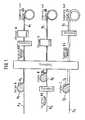
- Fig. 1 films A1 and C1 by conventional warping of slurry A2, C2 on a steel band A3, C3 forth g e-sets.
- the slip application takes place by means of a pressure vessel (not shown) via a casting shoe A4, C4, which is mounted motionless over the steel belt.
- the film thickness (from 0.2 to 1.5 mm) is determined by an adjustable gap height on the casting shoe.
- a photocell (not shown), which controls the addition of the slip via a compressed air system, ensures constant slip level in the casting shoe.
- the foils A1, C1 are later pulled off the steel strip A3, C3 (not shown).
- the film can be removed by pretreating the steel strip A3, C3 with a release agent (eg fish oil).
- a release agent eg fish oil
- the covered tape is equipped with an exhaust system and heating (drying) to evaporate solvent. Indoor air is drawn in via a heater (not shown), passed over the belt and finally sucked off.
- the film is cut to the desired width.
- positioning holes films A1, B1
- screen printing films A1, C1
- drying through a drying channel films A1, C1
- punching a window film A1
- storage on rolls A6, C6 are carried out. If the conductor tracks are not integrated, punching can also be carried out before screen printing.
- Screen printing A5 on film A1 is used to apply a lid metallization
- screen printing C5 on film C1 is used to apply conductor pads.
- a line pattern is first printed on a plastic carrier film B3 by means of screen printing B5. Positioning marks (not shown) are printed at the same time during the printing process. After drying, slip B2 is applied in the same way as described for foils A1, C1.
- the positioning markings are punched and the registration and recess or window are punched out.
- the film B1 is then taken on roll B6.
- FIG. 2 shows a detailed partial section from FIG. 1, from which the application and detachment of the ceramic films from the carrier tapes, shown on the film A1, can be seen.
- the carrier tape 26 is driven by rollers 24, 25.
- Screen printing A5 then takes place, which is used to apply a lid metallization, followed by further drying 27.
- the screen printing is done either synchronously, i.e. when the screen printing device is running, or when the film comes to a standstill in clocked mode.
- the upstream continuous casting process of the film remains unaffected by the special screen printing method.
- the film is then fed via a guide roller 28 to a take-up roller A6, a window being previously punched out by means of a punch 29.
- foils B1 and C1 In the case of foils B1 and C1, the production is carried out analogously, the differences apparent from FIG. 1 having to be taken into account.
- FIG. 3 shows the lamination process of the films A1, B1, C1 produced in FIG. 1.
- the foils A1, B1, C1 are pulled off rolls A6, B6, C6.
- the lamination is carried out using pairs of laminating rollers 8, 8 '; 9.9 '; 10, 10'; 11.11 '.
- guide rollers A12, B12 are provided.
- the laminating rollers are resiliently mounted in pairs against each other, so that pressures of 0.2 to 25 kp / cm 2 are exerted and in particular there is no deformation of the foils.
- the lamination takes place at low temperatures, maximum 60 ° C.
- the films B1 and C1 are first combined, whereupon the composite film B1C1 is laminated with the film A1.
- the exact positioning is achieved by optical pre-positioning and finally by mechanical positioning.
- the latter can be done either by means of positioning rollers which are provided with corresponding positioning pins or by means of a moving metal and plastic belt with positioning pins.
- fillers and / or laminating spray are used as laminating aids.
- the housing is punched (separated) using the positioning holes. This is followed by side metallization and then burning of the housing.
- the side metallization is carried out in the usual way by screen printing, pad printing or dipping.
- burning find temperatures of 1450 to 1750 o C, preferably 1550-1700 ° C, application.
- FIG. 4 shows the entire manufacturing process from the raw material to the fire of the multilayer housing and illustrates the different purposes of using filler and / or laminating spray in the laminating process.
Landscapes
- Engineering & Computer Science (AREA)
- Manufacturing & Machinery (AREA)
- Microelectronics & Electronic Packaging (AREA)
- Chemical & Material Sciences (AREA)
- Ceramic Engineering (AREA)
- Inorganic Chemistry (AREA)
- Laminated Bodies (AREA)
- Preparation Of Clay, And Manufacture Of Mixtures Containing Clay Or Cement (AREA)
- Fixed Capacitors And Capacitor Manufacturing Machines (AREA)
- Production Of Multi-Layered Print Wiring Board (AREA)
Abstract
Description
- Die Herstellung keramischer Mehrschichtgehäuse erfolgt aus keramischen Schlickern, die wiederum aus einem keramischen Rohstoff sowie organischen Binde- und Hilfsmitteln bestehen und aus denen keramische Folien hergestellt werden, die man im Grünzustand mit Metallpasten bedruckt, durch Stanzen die erforderlichen Durchbrüche (Fenster) anbringt, und dann mehrere Folienabschnitte vor dem Brennen zu einem Laminat vereinigt.
- Das Laminieren der übereinandergelegten und genau positionierten Folienabschnitte erfolgt durch Kalt- oder Heißpressen. Ein solches Verfahren ist aus der DE-AS 23 57 625 bekannt.
- Ein wesentlicher'Nachteil der bekannten Verfahren besteht darin, daß die Herstellung der Mehrschichtgehäuse diskontinuierlich erfolgt. Die Automationsmöglichkeiten sind durch die Laminierpressen beschränkt, deren Einsatz darüber hinaus zeitaufwendig ist.
- Eine Aufgabe der Erfindung besteht somit darin, ein verbessertes Verfahren zur Herstellung von keramischen Mehrschichtgehäusen zur Verfügung zu stellen, bei dem der Laminiervorgang kontinuierlich erfolgt.
- Gegenstand der Erfindung ist somit ein.Verfahren zur Herstellung keramischer Mehrschichtgehäuse zur Aufnahme elektronischer Schaltungen, wobei mehrere metallisierte und mit Durchbrechungen versehene Keramikfolien im Grünzustand durch Pressen laminiert und dann einem Sintervorgang unterworfen werden, das dadurch gekennzeichnet ist, daß man das Laminieren der grünen Keramikfolien kontinuierlich durch Walzen vornimmt.
- Das Verfahren der Erfindung ermöglicht eine weitgehende Automatisierung, da die nach der Herstellung der Einzelfolien bisher notwendigen Detailschritte, wie Stanzen, Positionieren und Laminieren, in einem kontinuierlichen Arbeitsgang durchgeführt werden können.
- Nach dem Verfahren der Erfindung erhält man Laminate mit weniger Lufteinschlüssen und sehr guter Kontaktflächenauflage. Demgemäß sind die Mehrschichtgehäuse gut-vakuumdicht, und die fertigen Bauelemente besitzen ausgezeichnete Werte für die Heliumleckrate.
- Nach dem Verfahren der Erfindung werden die einzelnen Keramikfolien vor dem Laminieren nicht zu Karten zerschnitten, die dann zu Kartensätzen aufeinandergestapelt werden, sondern die Folien werden in Bahnform dem Laminiervorgang durch Walzen unterworfen,und erst danach erfolgt gegebenenfalls das Ablängen und Stanzen der Verbundbahn für den Brennvorgang.
- Die Zufuhr der Einzelfolien für den Laminiervorgang erfolgt vorzugsweise von der Rolle. Es ist zwar auch möglich, die Herstellung der Einzelfolien so zu steuern, daß sie ohne Zwischenlagerung auf Rolle direkt dem Laminiervorgang unterworfen werden. Diese Arbeitsweise verlangt jedoch mit zunehmender Folienzahl einen erheblichen Aufwand in der Abstimmung der Herstellungsbedingungen, so daß die Arbeitsweise von der Rolle bevorzugt ist.
- In einer bevorzugten Ausführungsform des Verfahrens der Erfindung wird das Walzen mittels zweier gegenüberliegender Walzen, oder mittels mehrerer jeweils gegenüberliegender Walzenpaare durchgeführt. Hierdurch werden während des Laminiervorgangs relative Verschiebungen der Folien zueinander vermieden. Nach Maßgabe der Schichtdicken und der Anzahl der Einzelfolien kann man den Keramikfolienbahn-Stapel jedoch auch durch anders angeordnete Walzen, etwa nach Art eines Walzenstuhls oder eines Kalanders, führen.
- In einer weiteren bevorzugten Ausführungsform sind das oder die Walzenpaare synchron angetrieben, um eventuelle Beeinträchtigungen durch zu große Scherspannungen zu vermeiden.
- Der Laminiervorgang kann unter Verwendung eines horizontalen ebenen Tisches erfolgen, wobei das Walzenpaar (und gegebenenfalls jedes weitere Walzenpaar) vorzugsweise so angeordnet ist, daß sich der Walzenspalt in der Tischebene und senkrecht zur Laufrichtung der zusammengelegten Keramikfolienbahnen befindet. Anstelle des Tisches kann man auch eine Walzenstraße verwenden.
- Die übereinanderliegenden Keramikfolienbahnen werden hierbei entweder über den Tisch gezogen, wobei vorzugsweise dem Schlicker zur Erzielung besserer Gleiteigenschaften Trenn- bzw. Gleitmittel zugesetzt worden sind, oder man transportiert den Folienbahnstapel auf einem Stahlband, das mit durch den Walzenspalt hindurch läuft.
- Diese Stahlbandabdeckung des Folienbahnstapels kann auch beidseitig erfolgen. Bei besonders empfindlichen Schlickerrezepturen kann durch Verwendung der .Stahlbänder eine Verbesserung der Dickenkonstanz bzw. die Vermeidung einer Welligkeit erreicht werden.
- Erfindungsgemäß erfolgt das Laminieren bei Drücken von 0,2 bis 25 kp/cm2. Im Einzelfall richtet sich der angewendete Druck nach den Eigenschaften der Folie, wie Flexibilität und Schichtdicke.
- Hierbei ist insbesondere von Bedeutung, daß die Walzen unter Federdruck stehen und nicht starr gelagert sind. Auch kann es bei der Herstellung bestimmter Mehrschichtgehäuse wichtig sein, daß die Walzenoberfläche strukturiert ist. Die Profilgebung der Walzen richtet sich hierbei nach den Folienausnehmungen bzw. den Fensterabmessungen. Bei Verwendung von Profilwalzen arbeitet man zweckmäßig mit optischer Vorschubsteuerung.
- In einer weiteren bevorzugten Ausführungsform führt man den Laminiervorgang mit unbeheizten Walzen durch. Im allgemeinen tritt bei der Durchführung des Verfahrens keine größere Wärmeentwicklung auf. Sollte es trotzdem, u.U. auch klimatisch bedingt, zu Temperaturen von über 50°C oder sogar über 60°C kommen, wird vorzugsweise eine Temperaturabsenkung herbeigeführt, z.B. durch Kühlung der Laminierwalzen. Bei zu hohen Temperaturen kann es nach Maßgabe der angewendeten Schlickerrezepturen und der Geometrie zu unerwünschten Fließerscheinuhgen kommen.
- In einer weiteren bevorzugten Ausführungsform bringt man vor dem Zusammenführen der Keramikfolienbahnen für den Laminiervorgang einen Filler und/oder ein Spray als Laminierhilfsmittel auf. Hierbei handelt es sich im ersten Fall um ein Laminierhilfsmittel mit ähnlicher Rezeptur wie die zum Aufbringen der Leiterbahnmuster verwendeten Metallsiebdruckpasten, wobei jedoch im Filler der Metallanteil durch Keramik ersetzt ist. Diese Filler werden in sehr dünner Schicht durch Aufdrucken aufgebracht. Das Laminierspray als Klebemittel auf organischer Basis wird dagegen durch Aufsprühen aufgebracht. Die Anwendung von Laminierhilfsmitteln bringt mehrere Vorteile mit sich. Zum einen werden hierdurch niedrigere Drücke beim Laminiervorgang ermöglicht. Weiterhin erreicht man eine gute Standfestigkeit der Stege, und schließlich wirkt sich die Verwendung der Laminierhilfsmittel vorteilhaft bei der Vermeidung von Laminierfehlern aus.
- Vorzugsweise werden die Folienbahnen an beiden Außenkanten mit Positionierungsstellen versehen, die entweder mechanisch, z.B. durch Stanzen von Löchern für den Eingriff von Positionierstiften, oder durch optisch erkennbare Bilder vorgesehen werden, und die erst nach beendetem Laminiervorgang entfernt werden. Positionierstifte können sich an seitlichen Fördermitteln befinden, deren Vorschub durch den Walzenvorschub geregelt wird.
- Die erfindungsgemäß erzielten Laminiergeschwindigkeiten hängen ab von den Fließeigenschaften der Folie und den Positioniereinrichtungen. Hierbei wird die obere Grenze der Laufgeschwindigkeit in erster Linie davon bestimmt, daß Verformungen der Folien und der Ausstanzungen vermieden werden müssen. In der Praxis beträgt die Laminiergeschwindigkeit im allgemeinen 0,2 bis 2,5m/min.
- Man kann den Laminiervorgang so durchführen, daß sämtliche Keramikfolienbahnen in einem einzigen Arbeitsgang zusammenlaminiert werden. Man kann jedoch auch stufenweise vorgehen, indem z.B. bei Dreischichtgehäusen zunächst die Bahnen A und B und dann die Verbundbahn AB mit der Bahn C laminiert werden. Die Wahl der speziellen Arbeitsweise hängt hierbei z.B. auch von der gewünschten späteren Seitenmetallisierung bzw. Gehäuseform ab.
- Das Verfahren der Erfindung wird unter Verwendung üblicher Keramikfolien durchgeführt. Bevorzugt werden Keramikfolien, bei denen die Leiterbahnen in die Keramikmasse integriert sind. Die Herstellung solcher Keramik-Einzelfolien ist in der DE-AS 23 57 625 und der US-PS 3 870 776 beschrieben, auf die hier vollinhaltlich Bezug genommen wird.
- Das Aufdrucken der Leiterbahnen und anderen metallisierten Figuren (z.B. pads) erfolgt vorzugsweise nach üblichen Siebdruckverfahren in Dickfilmtechnik. Hierbei finden übliche Wolframpästen oder Molybdänpasten Verwendung.
- Bei Verwendung von Keramikfolien mit integrierten Leiterbahnen erfolgt zunächst der Druck der Leiterbahnen auf eine Trägerfolie, die nach dem Überdecken der Leiterbahn mit Keramikmasse wieder entfernt wird.
- Als Trägerfolien sind hierbei sowohl Kunststoff- als auch Metallbänder geeignet, wobei Stahlbänder eine bessere Festigkeit und Maßhaltegenauigkäit besitzen.
- Die getrockneten und gegebenenfalls mit Durchbrechungen (Fenstern) sowie Positionierungsstellen an den Seitenkanten versehenen Keramikfqlienbahnen werden dann vorzugsweise auf Rolle genommen.
- Für die Herstellung der erfindungsgemäß geeigneten Keramikfolienbahnen sind übliche Schlicker geeignet. Beispiele sind in der US-PS 2 966 719 und der DE-AS 23 57 625 beschrieben.
- Der Schlicker besteht aus keramischem Rohstoff, organischem Bindemittel, Dispergier- oder Verdünnungsmittel und gegebenenfalls Weichmachern und sonstigen Hilfsmitteln.
- Bevorzugt werden Schlicker, die 75 bis 97 Prozent Tonerde (Al2O3), vorzugsweise 85 bis 96 Prozent Tonerde, enthalten, wobei der Rest aus Sinterungshilfsmitteln und oxidischen Farbkörpern besteht. Als Sinterungshilfsmittel kommen z.B. Talkum bzw. Speckstein, Magnesiumoxid, Zirkonoxid, Wollastonit, Quarzmehl, Kaolin oder Zirkonsilikat in Frage.
- Das organische Bindemittel unterliegt an sich keiner besonderen Beschränkung, sofern eine gute Bindung gewährleistet ist und der Folie, gegebenenfalls in Kombination mit dem Weichmacher, die erforderliche Zähigkeit und Maßhaltegenauigkeit verliehen wird. Besonders gut.bewährt haben sich Polyvinylacetate und Polyvinylbutyral.
- Als Dispergier- oder Verdünnungsmittel dienen organische Lösungsmittel. Beispiele für geeignete organische Lösungsmittel sind Äthanol, Toluol, Trichloräthylen, usw.
- Zur Erzielung guter Folieneigenschaften beträgt die Viskosität des Schlickers vorzugsweise 4000 bis 7000 cP, bei einem Gehalt an keramischem Rohstoff von 55 bis 90 Prozent, vorzugsweise um etwa 70 Prozent.
- Ein besonders bevorzugtes Beispiel für eine schwarze Keramik ist nachfolgend angegeben. Hierbei findet als Farbkörper eine Kombination aus Chromoxid und Titandioxid Verwendung. Andere geeignete Farbkörper sind Eisenoxid, Mangancarbonat und Ammoniumparawolframat. Sofern eine weiße Keramik gewünscht wird, bleiben die Farbkörper weg.
- Zur Herstellung des Schlickers wird der keramische Rohstoff in solcher Menge in dem Binde- und Dispergiermittel gelöst, daß die Viskosität des erhaltenen Schlickers etwa 6500 cP beträgt. Der Schlicker besitzt dann einen Gehalt an keramischem Rohstoff von 59 bis 81 Gew.-%,z.B. 68 Gew.-%, bezogen auf Gesamtmasse.
-


- Erfindungsgemäß besonders geeignete Rahmenrezepturen für die Herstellung der Keramikfolien sind nachfolgend angegeben, wobei die Schlickerrezepturen nach Keramikrohstoff (einschließlich Farbkörper) und Binde- und Hilfsmittel aufgeschlüsselt sind.

-

- Fig. 1 In Form eines Fließschemas die Herstellung von grünen Einzelfolien für die Durchführung des Verfahrens der Erfindung,
- Fig. 2 Einen detaillierten Teilausschnitt von Fig.1,
- Fig. 3 Die Durchführung des Laminiervorgangs nach dem Verfahren der Erfindung, und
- Fig. 4 Ein Blockschema, das den gesamten Herstellungsvorgang vom Rohstoff über die Herstellung der Grünfolien und das Laminieren bis zum Brennen der Mehrschichtgehäuse veranschaulicht.
- In Fig. 1 werden Folien A1 und C1 durch übliches Verziehen von Schlicker A2, C2 auf einem Stahlband A3, C3 herge-stellt. Die Schlickeraufgabe erfolgt mittels eines Druckbehälters (nicht dargestellt) über einen Gießschuh A4, C4, der über dem Stahlband bewegungsfrei gelagert ist. Die Folienstärke (von 0,2 bis 1,5 mm) wird durch eine einstellbare Spalthöhe am Gießschuh bestimmt. Für gleichbleibendes Schlickerniveau im Gießschuh sorgt eine Fotozelle (nicht dargestellt), die über ein Druckluftsystem die Schlickerzugabe steuert. Die Folien A1,C1 werden später von dem Stahlband A3,C3 wieder abgezogen (nicht dargestellt).
- Die Ablösbarkeit der Folie wird durch Vorbehandeln des Stahlbandes A3,C3 mit einem Trennmittel (z.B. Fischöl) erzielt. Man arbeitet mit Bandgeschwindigkeiten von 10 cm/min bis 1 m/min, z.B. mit 20 cm/min, bei Bandlängen von 15 bis 25 m. Zur Verdampfung von Lösungsmittel ist das abgedeckte Band mit einem Abluftsystem und einer Heizung (Trocknung) ausgestattet. Raumluft wird über eine Heizung (nicht dargestellt) angesaugt, über das Band geführt und schließlich abgesaugt. Man arbeitet im Temperaturbereich von 40 bis 150°C.
- Am Bandende, nach Abschluß der Trocknung, wird die Folie auf die gewünschte Breite geschnitten. Nach dem Ablösen der Folie vom Trägerband erfolgt Anbringung von Positionierlöchern (Folien A1, B1), Siebdrucken (Folien A1, C1) Trocknen durch Trocknungskanal (Folien A1, C1), Stanzen eines Fensters (Folie A1) und Lagerung auf Rollen A6, C6. Bei nicht integrierten Leiterbahnen kann das Stanzen auch vor dem Siebdrucken erfolgen.
- Ein Siebdruck A5 bei der Folie A1 dient dem Aufbringen einer Deckelmetallisierung, ein Siebdruck C5 der Folie C1 dem Aufbringen von Leiterbahnflecken (pads).
- Bei der Herstellung einer Folie B1 mit integrierter Leiterbahn erfolgt zunächst Aufdrucken eines Leitungsmusters mittels Siebdruck B5 auf eine Kunststoff-Trägerfolie B3. Während des Druckvorgangs werden gleichzeitig Positioniermarkierungen (nicht dargestellt) mitgedruckt. Nach Trocknung erfolgt Aufziehen von Schlicker B2 in gleicher Weise wie bei den Folien A1, C1 beschrieben.
- Nach erneuter Trocknung und Abziehen der Trägerfolie B3 erfolgt optisches Erfassen der Positioniermarkierungen und Stanzen von Registrierung und Ausnehmung bzw. Fenster. Die Folie B1 wird dann auf Rolle B6 genommen.
- Fig. 2 zeigt einen detaillierten Teilausschnitt von Fig. 1, aus dem das Aufbringen und Ablösen der Keramikfolien von den Trägerbändern, dargestellt an der Folie A1, ersichtlich ist.
- Das Stahlband A3 wird von Walzen 21, 22 mit dem gewünschten Vorschub angetrieben. Nach dem Gießen der Folie A1 erfolgt eine erste Trocknung 23. Die Ablösung der getrockneten Folie A1 vom Stahlband A3 erfolgt in Höhe der Walze 22, wobei ein mehr oder weniger großer Durchhang der Folie (minimal = gestrichelte Linien, maximal = durchgezogene Linien) vor dem Auflaufen auf ein weiteres Trägerstahlband 26 vorgesehen ist. Das Trägerband 26 wird durch Walzen 24, 25 angetrieben.
- Es erfolgt dann der Siebdruck A5, der dem Aufbringen einer Deckelmetallisierung dient, worauf sich eine weitere Trocknung 27 anschließt. Der Siebdruck erfolgt hierbei entweder synchron, d.h. bei mitlaufender Siebdruckeinrichtung, oder bei Folienstillstand in getakteter Arbeitsweise. Der vorgeschaltete kontinuierliche Gießvorgang der Folie bleibt von der speziellen Siebdruck- Arbeitsweise unberührt.
- In Höhe der Walze 25 erfolgt die Ablösung der bedruckten und getrockneten Folie A1 vom Trägerband A26, wobei ein gewisser Durchhang der Folie (minimal = gestrichelte Linien, maximal = durchgezogene Linien) vorgesehen ist. Die Folie wird dann über eine Führungswalze 28 einer Aufnahmerolle A6 zugeführt, wobei zuvor mittels einer Stanze 29 ein Fenster ausgestanzt wird.
- Bei den Folien B1 und C1 erfolgt die Herstellung sinngemäß, wobei die aus Fig. 1 ersichtlichen Unterschiede zu berücksichtigen sind.
- In Fig. 3 ist der Laminiervorgang der in Fig. 1 hergestellten Folien A1, B1, C1 dargestellt.
- Die Folien A1, B1, C1 werden von Rollen A6, B6, C6 abgezogen. Das Laminieren erfolgt unter Verwendung von Laminierwalzenpaaren 8, 8'; 9,9';10, 10'; 11,11'. Darüber hinaus sind Führungswalzen A12, B12 vorgesehen.
- Die Laminierwalzen sind paarweise federnd gegeneinander gelagert, so daß Drücke von 0,2 bis 25 kp/cm2 ausgeübt werden und insbesondere keine Deformation der Folien stattfindet. Das Laminieren erfolgt bei niedrigen Temperaturen, maximal 60° C.
- Im vorliegenden Ausführungsbeispiel werden zunächst die Folien B1 und C1 vereinigt, worauf Laminierung der Verbundfolie B1C1 mit der Folie A1 erfolgt. Die genaue Positionierung wird hierbei durch optische Vorpositionierung und schließlich durch mechanische Positionierung erreicht. Letztere kann entweder durch Positionierwalzen, die mit entsprechenden Positionierstiften versehen sind oder durch ein mitlaufendes Metall- und Kunststoffband mit Positionierstiften erfolgen.
- Nach Maßgabe der Folienart (vgl. Fig. 4) finden als Laminierhilfsmittel Filler und/oder Laminierspray Verwendung.
- Nach beendetem Laminiervorgang erfolgt Stanzen (Vereinzeln) der Gehäuse mit Hilfe der Positionierlöcher. Hieran schließt sich eine Seitenmetallisierung und dann Brennen der Gehäuse an.
- Die Seitenmetallisierung erfolgt in üblicher Weise durch Siebdruck, Tampondruck oder Tauchen. Beim Brennen finden Temperaturen von 1450 bis 1750oC, vorzugsweise 1550 bis 1700°C, Anwendung.
- Das Blockschema von Fig. 4 zeigt den gesamten Herstellungsvorgang vom Rohstoff bis zum Brand der Mehrschichtgehäuse und verdeutlicht den unterschiedlichen Zweck der Anwendung von Filler und/oder Laminierspray beim Laminiervorgang.
- Bei der Verwendung von Folien mit erhabenen Leiterbahnen (rechte Seite von Fig. 4) ist die Anwendung eines Fillers zum Ausgleich des durch die erhabene Leiterbahn bedingten Höhenunterschiedes zweckmäßig. Demgegenüber ist bei Verwendung von Folien mit integrierter Leiterbahn (linke Seite von Fig. 4) die Verwendung eines Fillers entbehrlich.
Claims (10)
Priority Applications (3)
| Application Number | Priority Date | Filing Date | Title |
|---|---|---|---|
| DE8080101572T DE3061189D1 (en) | 1980-03-25 | 1980-03-25 | Process for the production of multi-layered ceramic casings |
| AT80101572T ATE1897T1 (de) | 1980-03-25 | 1980-03-25 | Verfahren zur herstellung von keramischen mehrschichtgehaeusen. |
| EP80101572A EP0036435B1 (de) | 1980-03-25 | 1980-03-25 | Verfahren zur Herstellung von keramischen Mehrschichtgehäusen |
Applications Claiming Priority (1)
| Application Number | Priority Date | Filing Date | Title |
|---|---|---|---|
| EP80101572A EP0036435B1 (de) | 1980-03-25 | 1980-03-25 | Verfahren zur Herstellung von keramischen Mehrschichtgehäusen |
Publications (2)
| Publication Number | Publication Date |
|---|---|
| EP0036435A1 true EP0036435A1 (de) | 1981-09-30 |
| EP0036435B1 EP0036435B1 (de) | 1982-12-01 |
Family
ID=8186641
Family Applications (1)
| Application Number | Title | Priority Date | Filing Date |
|---|---|---|---|
| EP80101572A Expired - Lifetime EP0036435B1 (de) | 1980-03-25 | 1980-03-25 | Verfahren zur Herstellung von keramischen Mehrschichtgehäusen |
Country Status (3)
| Country | Link |
|---|---|
| EP (1) | EP0036435B1 (de) |
| AT (1) | ATE1897T1 (de) |
| DE (1) | DE3061189D1 (de) |
Cited By (2)
| Publication number | Priority date | Publication date | Assignee | Title |
|---|---|---|---|---|
| EP0335294B1 (de) * | 1988-03-30 | 1992-06-03 | Hoechst CeramTec Aktiengesellschaft | Verfahren zur Herstellung von Gleitkörpern mit Hohlkammern |
| EP0536584A3 (en) * | 1991-10-11 | 1993-11-10 | Dyko Industriekeramik Gmbh | Process for the production of a composite material comprising at least two layers |
Citations (3)
| Publication number | Priority date | Publication date | Assignee | Title |
|---|---|---|---|---|
| DD115105A1 (de) * | 1974-11-28 | 1975-09-12 | ||
| CH593875A5 (de) * | 1971-04-16 | 1977-12-15 | Nl Industries Inc | |
| WO1980000013A1 (en) * | 1978-06-05 | 1980-01-10 | United States Gypsum Co | Method for the production of glass fiber-reinforced gypsum sheets and gypsum board formed therefrom |
-
1980
- 1980-03-25 EP EP80101572A patent/EP0036435B1/de not_active Expired - Lifetime
- 1980-03-25 AT AT80101572T patent/ATE1897T1/de active
- 1980-03-25 DE DE8080101572T patent/DE3061189D1/de not_active Expired - Lifetime
Patent Citations (3)
| Publication number | Priority date | Publication date | Assignee | Title |
|---|---|---|---|---|
| CH593875A5 (de) * | 1971-04-16 | 1977-12-15 | Nl Industries Inc | |
| DD115105A1 (de) * | 1974-11-28 | 1975-09-12 | ||
| WO1980000013A1 (en) * | 1978-06-05 | 1980-01-10 | United States Gypsum Co | Method for the production of glass fiber-reinforced gypsum sheets and gypsum board formed therefrom |
Cited By (2)
| Publication number | Priority date | Publication date | Assignee | Title |
|---|---|---|---|---|
| EP0335294B1 (de) * | 1988-03-30 | 1992-06-03 | Hoechst CeramTec Aktiengesellschaft | Verfahren zur Herstellung von Gleitkörpern mit Hohlkammern |
| EP0536584A3 (en) * | 1991-10-11 | 1993-11-10 | Dyko Industriekeramik Gmbh | Process for the production of a composite material comprising at least two layers |
Also Published As
| Publication number | Publication date |
|---|---|
| EP0036435B1 (de) | 1982-12-01 |
| ATE1897T1 (de) | 1982-12-15 |
| DE3061189D1 (en) | 1983-01-05 |
Similar Documents
| Publication | Publication Date | Title |
|---|---|---|
| EP0120192B1 (de) | Verfahren zur kontinuierlichen Herstellung kupferkaschierter Elektrolaminate und Vorrichtung zur DurchfÜhrung des Verfahrens | |
| DE4112047C2 (de) | Verfahren und Vorrichtung zur Herstellung keramischer Rohschichten für geschichtete, keramische Elektronikkomponenten | |
| EP0158027B2 (de) | Verfahren zum Herstellen von kupferkaschiertem Basismaterial für Leiterplatten | |
| DE69729013T2 (de) | Verfahren zur Herstellung eines dekorativen Laminates | |
| EP1459878B1 (de) | Wellpappe-Anlage sowie Verfahren zur Herstellung von Wellpappe-Bögen | |
| DE3716112C1 (de) | Verfahren und Vorrichtung zur Herstellung eines Einbandes oder dergleichen | |
| EP0531251B1 (de) | Verfahren zum Herstellen eines Wabenkerns aus einer bandförmigen Folie, Vorrichtung zur Durchführung des Verfahrens und Verwendung des Wabenkerns als Wabenkern von kontinuierlich hergestellten Verbundplatten | |
| EP0485895B1 (de) | Vorrichtung und Verfahren zum Herstellen eines mehrschichtigen Folienverbundes | |
| EP1459879A2 (de) | Verfahren zur Herstellung von Wellpappe-Bögen | |
| EP0485896A1 (de) | Vorrichtung und Verfahren zum Herstellen eines mehrschichtigen Folienverbundes | |
| EP3375623A1 (de) | Verfahren zur herstellung eines halbzeuges sowie halbzeug | |
| EP0546311A1 (de) | Vorrichtung und Verfahren zum Herstellen eines mehrschichtigen Folienverbundes | |
| CN1060435C (zh) | 一种制造层压复合材料的方法和装置 | |
| EP0036435B1 (de) | Verfahren zur Herstellung von keramischen Mehrschichtgehäusen | |
| WO2016177713A1 (de) | Produktionsanlage und verfahren zur herstellung von kfz-kennzeichenrohlingen | |
| WO2019219539A1 (de) | Wellpappeanlage | |
| DE2855804A1 (de) | Stranggiess- und plattierverfahren und vorrichtung zur herstellung von plattierten blechen | |
| EP0541027A1 (de) | Vorrichtung und Verfahren zum Herstellen eines mehrschichtigen Folienverbundes | |
| EP0225451A2 (de) | Verfahren zur Herstellung von metallkaschiertem Leiterplatten-Basismaterial und Vorrichtung zur Durchführung des Verfahrens | |
| EP3680112B1 (de) | Verbund aus einer trägerfolie und zwei klebeschichten, verfahren zur herstellung eines halbzeuges mit einem solchen verbund sowie halbzeug | |
| EP0353413A1 (de) | Faltenbalg | |
| EP0634282A1 (de) | Verfahren zur Herstellung eines Antikopierfilms | |
| DE3835027A1 (de) | Verfahren und vorrichtung zur kontinuierlichen herstellung von multilayer-schaltungen | |
| DE10251689A1 (de) | Verfahren zur Herstellung eines keramischen Laminats | |
| DE10221522A1 (de) | Vorrichtung und Verfahren zur Bearbeitung von Polystyrol-Hartschaum |
Legal Events
| Date | Code | Title | Description |
|---|---|---|---|
| PUAI | Public reference made under article 153(3) epc to a published international application that has entered the european phase |
Free format text: ORIGINAL CODE: 0009012 |
|
| 17P | Request for examination filed |
Effective date: 19810312 |
|
| AK | Designated contracting states |
Designated state(s): AT BE CH DE FR GB IT LU NL SE |
|
| ITF | It: translation for a ep patent filed | ||
| GRAA | (expected) grant |
Free format text: ORIGINAL CODE: 0009210 |
|
| AK | Designated contracting states |
Designated state(s): AT BE CH DE FR GB IT LU NL SE |
|
| PG25 | Lapsed in a contracting state [announced via postgrant information from national office to epo] |
Ref country code: NL Effective date: 19821201 Ref country code: FR Free format text: THE PATENT HAS BEEN ANNULLED BY A DECISION OF A NATIONAL AUTHORITY Effective date: 19821201 Ref country code: BE Effective date: 19821201 |
|
| REF | Corresponds to: |
Ref document number: 1897 Country of ref document: AT Date of ref document: 19821215 Kind code of ref document: T |
|
| REF | Corresponds to: |
Ref document number: 3061189 Country of ref document: DE Date of ref document: 19830105 |
|
| PG25 | Lapsed in a contracting state [announced via postgrant information from national office to epo] |
Ref country code: DE Effective date: 19830107 |
|
| PG25 | Lapsed in a contracting state [announced via postgrant information from national office to epo] |
Ref country code: AT Effective date: 19830325 |
|
| PG25 | Lapsed in a contracting state [announced via postgrant information from national office to epo] |
Ref country code: SE Effective date: 19830326 |
|
| PG25 | Lapsed in a contracting state [announced via postgrant information from national office to epo] |
Ref country code: LU Free format text: LAPSE BECAUSE OF NON-PAYMENT OF DUE FEES Effective date: 19830331 Ref country code: CH Effective date: 19830331 |
|
| NLV1 | Nl: lapsed or annulled due to failure to fulfill the requirements of art. 29p and 29m of the patents act | ||
| EN | Fr: translation not filed | ||
| REG | Reference to a national code |
Ref country code: CH Ref legal event code: PL |
|
| GBPC | Gb: european patent ceased through non-payment of renewal fee | ||
| GBPC | Gb: european patent ceased through non-payment of renewal fee | ||
| PG25 | Lapsed in a contracting state [announced via postgrant information from national office to epo] |
Ref country code: GB Effective date: 19881118 |
|
| EUG | Se: european patent has lapsed |
Ref document number: 80101572.8 Effective date: 19850610 |
|
| PLBE | No opposition filed within time limit |
Free format text: ORIGINAL CODE: 0009261 |
|
| STAA | Information on the status of an ep patent application or granted ep patent |
Free format text: STATUS: NO OPPOSITION FILED WITHIN TIME LIMIT |