EP0036452A1 - Bürstenanordnung für dynamoelektrische Maschinen - Google Patents
Bürstenanordnung für dynamoelektrische Maschinen Download PDFInfo
- Publication number
- EP0036452A1 EP0036452A1 EP80200257A EP80200257A EP0036452A1 EP 0036452 A1 EP0036452 A1 EP 0036452A1 EP 80200257 A EP80200257 A EP 80200257A EP 80200257 A EP80200257 A EP 80200257A EP 0036452 A1 EP0036452 A1 EP 0036452A1
- Authority
- EP
- European Patent Office
- Prior art keywords
- brush
- support element
- arrangement according
- brushes
- contact part
- Prior art date
- Legal status (The legal status is an assumption and is not a legal conclusion. Google has not performed a legal analysis and makes no representation as to the accuracy of the status listed.)
- Granted
Links
- 230000005540 biological transmission Effects 0.000 claims description 3
- 239000000969 carrier Substances 0.000 claims description 2
- 230000007246 mechanism Effects 0.000 description 3
- 238000001816 cooling Methods 0.000 description 2
- 230000018109 developmental process Effects 0.000 description 2
- 125000006850 spacer group Chemical group 0.000 description 2
- RYGMFSIKBFXOCR-UHFFFAOYSA-N Copper Chemical compound [Cu] RYGMFSIKBFXOCR-UHFFFAOYSA-N 0.000 description 1
- 240000003517 Elaeocarpus dentatus Species 0.000 description 1
- UFHFLCQGNIYNRP-UHFFFAOYSA-N Hydrogen Chemical compound [H][H] UFHFLCQGNIYNRP-UHFFFAOYSA-N 0.000 description 1
- 230000004323 axial length Effects 0.000 description 1
- 238000010276 construction Methods 0.000 description 1
- 229910052802 copper Inorganic materials 0.000 description 1
- 239000010949 copper Substances 0.000 description 1
- 229910052739 hydrogen Inorganic materials 0.000 description 1
- 239000001257 hydrogen Substances 0.000 description 1
- 238000003780 insertion Methods 0.000 description 1
- 230000037431 insertion Effects 0.000 description 1
- 238000007689 inspection Methods 0.000 description 1
- 238000009434 installation Methods 0.000 description 1
- 238000004519 manufacturing process Methods 0.000 description 1
- 238000000926 separation method Methods 0.000 description 1
Images



Classifications
-
- H—ELECTRICITY
- H01—ELECTRIC ELEMENTS
- H01R—ELECTRICALLY-CONDUCTIVE CONNECTIONS; STRUCTURAL ASSOCIATIONS OF A PLURALITY OF MUTUALLY-INSULATED ELECTRICAL CONNECTING ELEMENTS; COUPLING DEVICES; CURRENT COLLECTORS
- H01R39/00—Rotary current collectors, distributors or interrupters
- H01R39/02—Details for dynamo electric machines
- H01R39/38—Brush holders
- H01R39/40—Brush holders enabling brush movement within holder during current collection
Definitions
- the invention relates to a brush arrangement for dynamoelectric machines for the transmission of current from a fixed brush bridge via brushes to a rotating contact part, with fixed and mechanically connected to the brush bridge brush pockets for receiving and radial guidance of the brushes, the brushes for control purposes. and renewal purposes can be removed while the machine is running and live.
- a brush arrangement of this type is known, for example, from US Pat. No. 3,387,155.
- a brush with associated guide pocket and the pressure mechanism that presses the brush against the rotating contact part is separated from the fixed contact part, the brush bridge or the brush rulers. With the mechanical separation, the electrical connection is also interrupted.
- Plug-in brush holders of this type are described and illustrated, for example, in US Pat. No. 3,466,481 and CH-PS 504 797. While in these versions only individual brushes can be replaced together with the associated guide pockets or pressure mechanisms, other known arrangements provide for combining several brushes with their guide pockets and spring arrangements to form a structural unit which can be removed as a whole.
- An essential feature of all of these designs is that not only the brush that matters alone, but also the brush guide elements (brush pockets), the pressure device (spring) and the fastening means are combined to form a "brush holder plug-in unit" that can be removed while the machine is running is.
- An advantage of the plug-in units with multiple brushes is a considerably faster control and a faster exchange of expired coals, which plays an essential role especially in large machines with up to 100 and more brushes.
- the brush pockets are an integral part of the fixed brush bridge, which form the brush ruler, while the brushes on brush support elements, which are at the same time carriers of the springs for pressing the brushes onto the rotating contact part , are arranged to be movable in the radial direction, and the assembly consisting of brush (s) and the brush support element can be pushed into the fixed brush pockets, locked in the inserted operating position and at the same time electrically connected to the brush pockets via a contact arrangement.
- the advantage of the invention can be seen in particular in the fact that only the component to be checked and / or replaced, namely the brush, and as few additional components as possible have to be separated from the brush bridge, whereas those components which essentially determine the rigidity of the entire brush arrangement , are left in their rigid connection with the machine.
- This also reduces the weight and dimensions of the retractable and retractable components that are in operation while the machine is in operation, which makes them more convenient and therefore safer to handle.
- Another advantage is the lower space requirement compared to the known, since the brush bridge can be designed as a rigid box girder. On the one hand, this enables a larger number of brushes to be accommodated, but on the other hand it also allows the cooling air to be guided in a targeted manner.
- the brush support element has one or more stops which cooperate with the brush or brushes to limit the radial movement of the brush both in the retracted operating position and in the extended service position.
- the stops are arranged and designed such that the brush is positioned in the extended position so that it can be inserted into the brush pocket (s) with the brush carrying element, and the stop or guide elements release the brush (s) after retracting and lifting off the end stop so that the brush (s) is no longer on Brush support element but is guided in the brush pocket.
- the brush support elements are plate-shaped and at the end facing the rotating contact part are provided with a number of finger-like extensions corresponding to the brushes, which extend into the brush pockets.
- the brush support elements are guided in radially extending slots in the brush pockets or the brush bridge (claim 5).
- the brush support elements are provided with a pawl which interacts with a cam or recess arranged on the outside of the brush pocket in such a way that it is safe in the retracted operating position and only by an intentional exterior Removable intervention, is held.
- a plug contact arrangement is provided for the electrical connection between the brush support element and the brush pocket or brush ruler, wherein the one contact part on the brush support element, the other contact part arranged the brush pocket, preferably integrally formed therewith.
- the brushes have a head fitting, which is provided on the side facing the brush support element with one or more projections which engage in radially extending recesses in the brush support element to grab.
- the maximum radial stroke of the brush can be determined by the length of the recess (claim 9) or by appropriate choice of the length of the flexible connecting line between the brush and the brush support element (claim 10).
- the brushes are also provided with a head fitting which is provided with projections on the side facing the brush support element, which projections preferably surround the brush support element laterally.
- a head fitting which is provided with projections on the side facing the brush support element, which projections preferably surround the brush support element laterally.
- the springs for pressing the brush onto the rotating contact part are attached to the brush support element with the interposition of a spring support plate, the spring support plate protruding laterally beyond the contact part end of the brush support element and being encompassed by the projections of the head fitting.
- lateral recesses with a length smaller than the radial height of the projections of the head fitting are provided in the section on the contact part side.
- the end facing away from the rotating contact part is provided with an insulated handle or is designed as such.
- the handle is also shielded by an insulating plate.
- the actuating member for locking the brush support element is also electrically insulated and extends through the insulating plate (claim 16).
- 1 denotes the rotating contact part (slip ring or commutator).
- the side walls 2 of the brush bridge are anchored on a foundation plate 3 in an electrically insulated manner.
- Brush rulers 4 are rigidly fastened between the brush bridge cheeks 2.
- the brush ruler 4 is designed as a box girder.
- the axially extending side walls are spaced apart by webs 5, so that brush pockets 6 are formed.
- the webs 5 each have a slot 7, the depth of which corresponds approximately to half the web height.
- the outward-facing edges of the brush pockets are rounded off to facilitate the retraction of the brushes (Fig. 4, positions 4 'and 5').
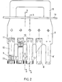
- Fig. 2 shows a plug-in unit for several brushes.
- the plug-in unit comprises a plate 8 with a plurality of finger-shaped extensions 8 'corresponding to the number of brushes.
- Roll band springs 9 are fastened to the plate 8 by means of rivets 11 with the interposition of spring support elements 10.
- the spring support elements 10 are provided on both sides with recesses 12 on the lower, ie contact part side, the ends of the spring support elements 10 are widened by riveting a stop plate 13. As can be seen from the sectional view of FIG. 4 and the view according to FIG.
- the brushes 14 have a head fitting 15 made of sheet copper, which is fastened to the brush 14 in an electrically conductive manner.
- the head fitting 15 has projections 16 on the side facing the spring support element 10, the ends of which are bent towards one another. These projections laterally encompass the spring support element 10. The width of the projections 16 is greater than the length of the recesses 12.
- the brush can be pushed onto (and pulled off) the spring support element 10 by being inserted obliquely.
- the electrical connection between the brush 14 and the brush support plate 8 is made by brush strands 17, which are on the one hand on the head fitting 15 and on the other hand on the brush support plate 8 are consolidated.
- the brush support plate 8 is formed at the upper end as an insulated handle 18 (Fig. 2).
- the insulated handle 18 is shielded from the rest of the brush support element by an insulating plate 19, which at the same time serves as protection against touching the brush wires and the brush rulers. In this way, a safe insertion or extension of the plug-in unit during operation and under voltage is made possible.
- the electrical connection between the brush support element 8 and the brush ruler 4 takes place, as illustrated in FIG. 4, by a plug contact arrangement.
- One contact part comprises resilient contact lamellae 20, which are attached to the brush support element 8 with the interposition of a conductive spacer 21.
- the other contact part is the brush ruler 4 itself.
- the plug-in unit is mechanically locked in the brush bridge by a pawl 23 (FIG. 5), which is mounted on the side of the brush-carrying element 8 facing away from the brushes and is preloaded by a leaf spring 22 (FIG. 5).
- the pawl has an insulated actuating lever 24 which extends through the insulating plate 19. The pawl engages in a recess 25 in the brush ruler 4. Depending on the axial length of the brush support elements. 8 two or more detents are provided.
- the subject of the invention is of course not limited to that shown in FIGS. 1 to 6.
- the spring support elements 10 can be omitted, and the springs 9 be directly on the brush support element 8 be consolidated.
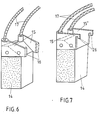
- Brushes with other head fittings 15 are also possible, e.g. those as shown in Figures 7 and 8, for example.
- 7 has a head fitting 15 'which is provided with hook-like projections 26.
- the projections are arranged on the side of the brush facing the brush support element 8 and point in the direction of the rotating contact part 1.
- the hook-like projections 26 engage parallel slots in the direction of the rotating contact part in the brush support element or (when using a spring support element) in the latter (in the Drawing not shown).
- the length of the slots corresponds to the maximum stroke of the brush. Additional slings are not necessary.
- a roller band spring can preferably be used as the spring for pressing the brush.
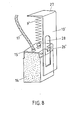
- a hook-like projection 26 ′ of the head fitting 15 ′′ of the brush 14 engages in a slot 28 that runs in the direction of the rotating contact part 1 and has a length that corresponds to the maximum stroke of the brush.
- the spring for pressing the brush against the rotating contact part is designed as a torsion spring 9 '. It is supported on the one hand on the head fitting 15 ′′ and on the other hand on the inwardly bent end 27 of the spring support element 10 ′.
- the brush is positioned on the brush support element so that the brush can be inserted into the brush pocket without tilting. Retracting the brushes is also facilitated by the rounded edges of the brush pockets.
- the brush is released when moving in at the moment of contact with the rotating contact part and when lifting off the end stop in such a way that the brush is no longer guided on the brush support element or spring support element but in the brush pocket.
- the handling of the brush connector unit is safe when the machine is running and live.
- the means for locking the plug-in unit in operation and unlocking it for inspection and replacement purposes are simple in structure. The same applies to the transmission of the current from the brush ruler to the brush support element.
- the subject of the invention does not require a completely new concept Brushed and / or head fittings, since practically only the head fittings of conventional brushes need to be slightly modified.
Landscapes
- Motor Or Generator Current Collectors (AREA)
Abstract
Description
- Die Erfindung bezieht sich auf eine Bürstenanordnung für dynamoelektrische Maschinen zur Uebertragung von Strom von einer feststehenden Bürstenbrücke über Bürsten auf einen rotierenden Kontaktteil, mit feststehenden und mit der Bürstenbrücke mechanisch und elektrisch verbundenen Bürstentaschen zur Aufnahme und radialen Führung der Bürsten, wobei die Bürsten zu Kontroll- und Erneuerungszwecken bei laufender Maschine und unter Spannung entfernbar sind. Eine Bürstenanordnung dieser Art ist beispielsweise aus der US-PS 3,387,155 bekannt.
- Mit immer grösser werdenden Maschineneinheiten, insbesondere bei Turbogeneratoren und Hydrogeneratoren, kommt dem ununterbrochenen Betrieb eine vorrangige Bedeutung zu. Besitzen solche Maschinen Bürstenapparate, dann ist ein Stillsetzen allein zum Zweck der Bürstenkontrolle oder zum Auswechseln abgelaufener Bürsten unerwünscht, da ein jeder Stillstand mit einem beträchtlichen Produktionsausfall verbunden ist. Aus diesem Grunde wurden in der jüngsten Vergangenheit verschiedene Bürstenhalteranordnungen geschaffen, die ein Auswechseln der Bürsten bei laufender und unter Spannung stehender Maschine ermöglichen.
- Bei einigen von diesen bekannten Anordnungen wird jeweils eine Bürste mit zugehöriger Führungstasche und dem Druckmechanismus, der die Bürste gegen den rotierenden Kontaktteil (Schleifring, Kommutator) presst, vom feststehenden Kontaktteil, der Bürstenbrücke oder den Bürstenlinealen abgetrennt. Mit der mechanischen Trennung wird auch die elektrische Verbindung unterbrochen. Steckbürstenhalter dieser Art sind beispielsweise in der US-PS 3,466,481 und der CH-PS 504 797 beschrieben und dargestellt. Während bei diesen Ausführungen jeweils nur einzelne Bürsten zusammen mit den zugehörigen Führungstaschen bzw. Druckmechanismen ausgewechselt werden können, sehen andere bekannte Anordnungen vor, mehrere Bürsten mit ihren Führungstaschen und Federanordnungen zu einer Baueinheit zusammenzufassen, die als Ganzes abnehmbar ist.
- Wesentliches Merkmal all dieser Ausführungen ist, dass nicht nur die Bürste, auf die es allein ankommt, sondern auch die Bürstenführungselemente (Bürstentaschen), der Druckapparat (Feder) und die Befestigungsmittel zu einer "Bürstenhalter-Steckeinheit" zusammengefasst werden, die bei laufender Maschine abziehbar ist. Ein Vorteil der Steckeinheiten mit mehreren Bürsten ist eine beträchtlich schnellere Kontrolle und ein schnellerer Austausch abgelaufener Kohlen, was insbesondere bei Grossmaschinen mit bis 100 und mehr Bürsten eine wesentliche Rolle spielt.
- Bei hochtourigen dynamoelektrischen Maschinen, insbesondere Turbogeneratoren, Turboerregern und Unipolarmaschinen, ist eine wesentliche Forderung an die Bürstenapparate, dass die die Bürste führende Bürstenhaltertasche sehr vibrationssteif ausgebildet und starr mit dem ruhenden Teil, der Bürstenbrücke verbunden sein muss. Dies erfordert bei den bekannten Steckeinheiten, insbesondere bei solchen mit mehreren Bürsten, eine extrem steife Konstruktion und eine kräftige Befestigungsmechanik. Die Steckeinheiten werden dadurch zwangsläufig voluminös, schwer und unbequem in der Handhabung. Zudem beschneidet der von ihnen eingenommene Raum die für die Kühlluftführung notwendigen Strömungsquerschnitte. Besonders gravierend fällt der Raumbedarf solcher Steckeinheiten bei grossen Turbogeneratoren ins Gewicht, wo sich die erforderliche Anzahl Bürsten auf den durch andere Rahmenbedingungen begrenzten Schleifringen kaum mehr unterbringen lassen.
- Es ist Aufgabe der Erfindung, eine Bürstenanordnung zu schaffen, die sich durch geringen Platzbedarf bei hoher Steifigkeit auszeichnet und bequem handhabbar ist.
- Diese Aufgabe wird bei einer Bürstenanordnung der eingangs genannten Gattung dadurch gelöst, dass erfindungsgemäss die Bürstentaschen ein integraler Bestandteil der feststehenden Bürstenbrücke sind, die das Bürstenlineal bilden, während die Bürsten auf Bürstentragelementen, die gleichzeitig Träger der Federn zum Anpressen der Bürsten an den rotierenden Kontaktteil sind, in radialer Richtung beweglich angeordnet sind, und die aus Bürste(n) und dem Bürstentragelement bestehende Baugruppe in die feststehenden Bürstentaschen einschiebbar, in der eingeschobenen Betriebsstellung arretierbar und gleichzeitig über eine Kontaktanordnung mit den Bürstentaschen elektrisch verbindbar ist.
- Der Vorteil der Erfindung ist insbesondere darin zu sehen, dass nur das zu kontrollierende und/oder auszuwechselnde Bauteil, nämlich die Bürste, und möglichst wenig zusätzliche Bauteile von der Bürstenbrücke getrennt werden müssen, während diejenigen Bauteile, welche im wesentlichen die Steifigkeit der gesamten Bürstenanordnung bestimmen, in ihrer starren Verbindung mit der Maschine belassen werden. Damit reduzieren sich auch Gewicht und Dimension der während des Betriebes der Maschine und unter Spannung stehenden aus- bzw. einfahrbaren Bauteile, was deren Handhabung .bequemer und damit auch sicherer macht. Vorteilhaft ist ferner der gegenüber dem Bekannten geringere Platzbedarf, da die Bürstenbrücke als steifer Kastenträger ausgebildet werden kann. Dies ermöglicht einerseits die Unterbringung einer grösseren Anzahl von Bürsten, andererseits aber auch eine gezielte Führung der Kühlluft.
- Gemäss der Ausführungsform des Erfindungsgegenstandes nach Anspruch 2 weist das Bürstentragelement einen oder mehrere, mit der bzw. den Bürsten zusammenwirkende Anschläge zur Begrenzung der Radialbewegüng der Bürste sowohl in der eingefahrenen Betriebsstellung als auch in der ausgefahrenen Servicestellung auf.
- Die Anschläge sind dabei gemäss der im Anspruch 3 definierten' Weiterbildung derart angeordnet und ausgebildet, dass die Bürste in der ausgefahrenen Stellung so positioniert ist, dass diese mit dem Bürstentragelement in die Bürstentasche(n) eingeführt werden kann, und die Anschlag- bzw. Führungselemente die Bürste(n) nach dem Einfahren und dem Abheben vom Endanschlag so freigeben, dass die Bürste(n) nicht mehr am Bürstentragelement sondern in der Bürstentasche geführt wird.
- Nach Anspruch 4 sind die Bürstentragelemente plattenförmig ausgebildet und an dem dem rotierenden Kontaktteil zugewandten Ende mit einer den Bürsten entsprechenden Anzahl von fingerartigen Fortsätzen versehen, welche in die Bürstentaschen hineinreichen. Die Bürstentragelemente sind dabei in radial verlaufenden Schlitzen in den Bürstentaschen bzw. der Bürstenbrücke geführt (Anspruch 5).
- Gemäss Anspruch 6 sind zur Arretierung der Bürste(n) und Bürstentragelement umfassenden Baugruppe die Bürstentragelemente mit einer Sperrklinke versehen, die mit einem auf der Aussenseite der Bürstentasche angeordneten Nocken oder Ausnehmung so zusammenwirkt, dass diese in der eingefahrenen Betriebsstellung sicher und, nur durch gewollten äusseren Eingriff lösbar, festgehalten wird.
- Während die elektrische Verbindung zwischen Bürste und Bürstentragelement (in an sich bekannter Weise) durch flexible Verbindungsleitungen erfolgt, ist zur elektrischen Verbindung zwischen Bürstentragelement und Bürstentasche bzw. Bürstenlineal gemäss Anspruch 6 eine Steckkontaktanordnung vorgesehen, wobei das eine Kontaktteil auf dem Bürstentragelement, das andere Kontaktteil an der Bürstentasche angeordnet, vorzugsweise einstückig mit diesem ausgebildet ist.
- Nach Anspruch 8 weisen die Bürsten eine Kopfarmatur auf, die auf der dem Bürstentragelement zugewandten Seite mit einem oder mehreren Vorsprüngen versehen ist, welche in radial verlaufende Ausnehmungen im Bürstentragelement eingreifen. Der maximale radiale Hub der Bürste kann dabei durch die Länge der Ausnehmung (Anspruch 9) oder durch entsprechende Wahl der Länge der flexiblen Verbindungsleitung zwischen Bürste und Bürstentragelement (Anspruch 10) bestimmt werden.
- Bei einer im Anspruch 11 gekennzeichneten alternativen Ausführungsform sind die Bürsten gleichfalls mit einer Kopfarmatur versehen, die auf der dem Bürstentragelement zugewandten Seite mit Vorsprüngen versehen ist, welche Vorsprünge das Bürstentragelement vorzugsweise seitlich umfassen. Zur Begrenzung des radialen Hubes der Bürste sind entweder die kontaktteilseitigen Enden der Bürstentragelemente mit Anschlagkanten, die mit den den Vorsprüngen der Kopfarmatur zusammenwirken, versehen (Anspruch 12)., oder es bestimmt die Länge der flexiblen Verbindungsleitung zwischen Bürste und Bürstentragelement den maximalen radialen Hub der Bürste.
- Bei plattenförmigen Bürstentragelementen ist es vorteilhaft, wenn gemäss Anspruch 13 die Federn zur Anpressung der Bürste an den rotierenden Kontaktteil unter Zwischenschaltung einer Federtragplatte auf dem Bürstentragelement befestigt sind, wobei die Federtragplatte das kontaktteilseitige Ende des Bürstentragelements seitlich überragt und von den Vorsprüngen der Kopfarmatur umfasst wird. Dies vereinfacht die Bearbeitung des Bürstentragelements und ermöglicht die Verwendung unterschiedlicher Bürsten- und/oder Kopfarmaturtypen, indem allein die Federtragplatte den jeweiligen Verhältnissen angepasst werden muss.
- Bei einer weiteren vorteilhaften Weiterbildung des Erfindungsgegenstandes nach Anspruch 14 sind im kontaktteilseitigen Abschnitt seitliche Ausnehmungen mit einer Länge kleiner als die radiale Höhe der Vorsprünge der Kopfarmatur vorgesehen. Durch diese Ausnehmungen lässt sich die Bürste (im ausgebauten Zustand des Bürstentragelementes) schräg ein- bzw. ausfahren. Eine Verbreiterung am kontaktteilseitigen Ende der Federtragplatte begrenzt den radialen Hub der Bürste sowohl beim Einbau als auch während des Betriebes gegen Abnützung über ein maximal zulässiges Mass hinaus.
- Zur gefahrlosen Handhabung des Bürstentragelements ist nach Anspruch 15 dessen dem rotierenden Kontaktteil abgewandtes Ende mit einem isolierten Handgriff versehen oder als solcher ausgebildet. Der Handgriff ist zusätzlich durch eine Isolierplatte abgeschirmt. Auch das Betätigungsorgan für die Arretierung des Bürstentragelements ist elektrisch isoliert und reicht durch die Isolierplatte hindurch (Anspruch 16).
- Die Erfindung wird nachstehend anhand der Zeichnung, in der Ausführungsbeispiele des Erfindungsgegenstandes dargestellt sind, näher erläutert.
- In der Zeichnung zeigt
- Fig. 1 eine perspektive Darstellung einer Bürstenanordnung für dynamoelektrische Maschinen in stark vereinfachter Form,
- Fig. 2 eine Draufsicht auf ein Bürstentragelement,
- Fig. 3 einen Längsschnitt durch ein Bürstentragelement gemäss Fig. 2 längs deren Linien A-A,
- Fig. 4 einen Längsschnitt durch ein Bürstentragelement gemäss Fig. 2 längs deren Linien B-B,
- Fig. 5 einen Radialschnitt durch die Bürstenanordnung gemäss Fig. 1 mit eingesetztem Bürstentragelement,
- Fig. 6 eine perspektivische Ansicht einer Bürste mit Kopfarmatur, wobei die Kopfarmatur mit nach innen gebogenen Vorsprüngen versehen ist,
- Fig. 7 ein Ausführungsbeispiel einer Bürste mit einer Kopfarmatur, die paarig angeordnete, nach innen weisende hakenartige Vorsprünge aufweist,
- Fig. 8 ein weiteres Ausführungsbeispiel einer Bürste, deren Kopfarmatur einen mittig angeordneten, nach innen weisenden hakenartigen Vorsprung aufweist.
- In der vereinfachten Darstellung der Schleifringpartie einer dynamoelektrischen Maschine gemäss Fig. 1 ist mit 1 der rotierende Kontaktteil (Schleifring oder Kommutator) bezeichnet. Die Seitenwangen 2 der Bürstenbrücke sind auf einer Fundamentplatte 3 elektrisch isoliert verankert. Zwischen den Bürstenbrückenwangen 2 sind Bürstenlineale 4 starr befestigt. Das Bürstenlineal 4 ist als Kastenträger ausgebildet. Die axial verlaufenden Seitenwände sind durch Stege 5 distanziert, so dass Bürstentaschen 6 gebildet sind.
- Die Stege 5 weisen je einen Schlitz 7 auf, dessen Tiefe etwa der halben Steghöhe entspricht. Die nach aussen weisenden Kanten der Bürstentaschen sind zur Erleichterung des Einfahrens der Bürsten abgerundet (Fig. 4, Positionen 4' und 5').
- Fig. 2 zeigt eine Steckeinheit für mehrere Bürsten. Die Steckeinheit umfasst eine Platte 8 mit mehreren fingerförmigen Fortsätzen 8' entsprechend der Anzahl der Bürsten. Die Fortsätze 8' ragen in die Bürstentaschen 6 hinein und liegen an der in Drehrichtung des rotierenden Kontaktteils 1 gesehen auflaufenden Wandung der Bürstentasche 6 an (Fig. 4). Auf der Platte 8 sind Rollbandfedern 9 unter Zwischenschaltung von Federtragelementen 10 mittels Nieten 11 befestigt. Am unteren, d.h. kontaktteilseitigen Abschnitt sind die Federtragelemente 10 beidseitig mit Ausnehmungen 12 versehen, die Enden der Federtragelemente 10 sind durch Mitaufnieten eines Anschlagplättchens 13 verbreitert. Wie aus der Schnittdarstellung der Fig. 4 und der Ansicht nach Fig. 6 hervorgeht, besitzen die Bürsten 14 eine Kopfarmatur 15 aus Kupferblech, die an der Bürste 14 elektrisch leitend befestigt ist. Die Kopfarmatur 15 weist auf der dem Federtragelement 10 zugewandten Seite Vorsprünge 16 auf, deren Enden aufeinanderzugebogen sind. Diese Vorsprünge umfassen das Federtragelement 10 seitlich. Die Breite der Vorsprünge 16 ist grösser als die Länge der Ausnehmungen 12. Durch schräges Einführen lässt sich die Bürste auf das Federtragelement 10 aufschieben (und wieder abziehen). Die elektrische Verbindung zwischen Bürste 14 und der Bürstentragplatte 8 erfolgt durch Bürstenlitzen 17, die einerseits an der Kopfarmatur 15, andererseits an der Bürstentragplatte 8 befestigt sind. Die Bürstentragplatte 8 ist am oberen Ende als isolierter Handgriff 18 ausgebildet (Fig. 2). Zusätzlich ist der isolierte Handgriff 18 vom restlichen Bürstentragelement durch eine Isolierplatte 19 abgeschirmt, die gleichzeitig als Schutz gegen Berührung der Bürstenlitzen und die Bürstenlineale dient. Auf diese Weise wird ein gefahrloses Einführen bzw. Ausfahren der Steckeinheit im Betrieb und unter Spannung ermöglicht.
- Die elektrische Verbindung zwischen dem Bürstentragelement 8 und dem Bürstenlineal 4 erfolgt,wie in Fig. 4 veranschaulicht, durch eine Steckkontaktanordnung. Der eine Kontaktteil umfasst federnde Kontaktlamellen 20, die unter Zwischenschaltung eines leitenden Distanzstückes 21 auf dem Bürstentragelement 8 befestigt sind. Den anderen Kontaktteil bildet das Bürstenlineal 4 selbst.
- Die mechanische Arretierung der Steckeinheit in der Bürstenbrücke erfolgt durch eine auf der den Bürsten abgewandten Seite des Bürstentragelements 8 gelagerte, durch eine Blattfeder 22 vorgespannte Sperrklinke 23 (Fig. 5). Die Sperrklinke weist einen isolierten, durch die Isolierplatte 19 hindurchreichenden Betätigungshebel 24 auf. Die Klinke greift in eine Ausnehmung 25 im Bürstenlineal 4 ein. In Abhängigkeit von der axialen Länge der Bürstentragelemente . 8 sind zwei oder mehrere Arretierungen vorgesehen.
- Der Erfindungsgegenstand ist selbstverständlich nicht auf das in den Figuren 1 bis 6 Dargestellte beschränkt. So können beispielsweise die Federtragelemente 10 entfallen, und die Federn 9 direkt auf dem Bürstentragelement 8 befestigt werden.
- Auch sind Bürsten mit anderen Kopfarmaturen 15 möglich, z.B. solche, wie sie in den Figuren 7 und 8 beispielsweise dargestellt sind. So weist die Bürste nach Fig. 7 eine Kopfarmatur 15' auf, die mit hakenartigen Vorsprüngen 26 versehen ist. Die Vorsprünge sind auf der dem Bürstentragelement 8 zugewandten Seite der Bürste angeordnet und weisen in Richtung des rotierenden Kontaktteils 1. Die hakenartigen Vorsprünge 26 greifen in Richtung des rotierenden Kontaktteils verlaufende parallele Schlitze im Bürstentragelement oder (bei Verwendung eines Federtragelements) im letzteren ein (in der Zeichnung nicht dargestellt). Die Länge der Schlitze entspricht dabei dem maximalen Hub der Bürste. Zusätzliche Anschlagmittel sind dabei entbehrlich. Als Feder für die Anpressung der Bürste kann vorzugsweise eine Rollbandfeder Verwendung finden.
- Auch bei der in Fig. 8 dargestellten Variante greift ein hakenartiger Vorsprung 26' der Kopfarmatur 15" der Bürste 14 in einen in Richtung des rotierenden Kontaktteils 1 verlaufenden Schlitz 28 mit einer Länge, die dem maximalen Hub der Bürste entspricht, ein.
- In Abwandlung zu den bisher beschriebenen Ausführungen ist in Fig. 8 die Feder für die Anpressung der Bürste an den rotierenden Kontaktteil als Drehfeder 9' ausgebildet. Sie stützt sich einerseits an der Kopfarmatur 15", andererseits an dem nach innen umgebogenen Ende 27 des Federtragelements 10' ab.
- Allen vorstehend beschriebenen Ausführungsformen gemeinsam sind folgende Eigenschaften:
- Die Verbindung zwischen Bürste und Bürstentragelement ist so beschaffen, dass die Bürste in Radialrichtung, und zwar auch im ausgefahrenen Zustand, sich nicht über eine Endstellung hinaus bewegen kann. Diese Endstellung entspricht im eingefahrenen Zustand der maximal zulässigen Bürstenabnützung.
- Die Bürste ist am Bürstentragelement so positioniert, dass die Bürste ohne zu verkanten in die Bürstentasche eingefahren werden kann. Erleichtert wird das Einfahren der Bürsten ferner durch die abgerundeten Kanten der Bürstentaschen.
- Die Bürste wird beim Einfahren im Moment des Kontaktes mit dem rotierenden Kontaktteil und beim Abheben vom Endanschlag so freigegeben, dass die Bürste nicht mehr am Bürstentragelement bzw. Federtragelement sondern in der Bürstentasche geführt wird.
- .Darüber hinaus ist die Handhabung der Bürstensteckeinheit bei laufender und unter Spannung stehender Maschine gefahrlos. Die Mittel zur Arretierung der Steckeinheit im Betrieb und deren Deblockierung zu Inspektions- und Erneuerungszwecken sind einfach im Aufbau. Gleiches gilt für die Uebertragung des Stromes vom Bürstenlineal zum Bürstentragelement.
- Der Erfindungsgegenstand erfordert keine gänzlich neukonzipierte Bürsten- und/oder Kopfarmaturen, da praktisch nur die Kopfarmatur herkömmlicher Bürsten geringfügig modifiziert werden muss.
-
- 1 rotierender Kontaktteil (Schleifring, Kommutator)
- 2 Bürstenbrückenwange
- '3 Fundamentplatte
- 4 Bürstenlineal
- 5 Steg
- 6 Bürstentasche
- 7 Schlitz in den Stegen 5
- 8 Bürstentragelement
- 8' fingerförmiger Fortsatz des Bürstentragelements 8
- 9 Rollbandfeder
- 9' Drehfeder
- 10 Federtragelement
- 10' Federtragelement mit abgewinkeltem Ende
- 11 .Nieten
- 12 Ausnehmung im Federtragelement 10
- 13 Anschlagplättchen
- 14 Bürste
- 15 15' Kopfarmaturen der Bürste 14 15"
- 16 nach innen umgebogene Vorsprünge der Kopfarmatur 15
- 17 Bürstenlitze
- 18 isolierter Handgriff
- 19 Isolierplatte
- 20 federnde Kontaktlamellen
- 21 Distanzstück
- 22 Blattfeder
- 23 Sperrklinke
- 24 Betätigungshebel
- 25 Ausnehmung im Bürstenlineal 4
- 26 hakenartiger Vorsprung der Kopfarmatur 15'
- 26' hakenartiger Vorsprung der Kopfarmatur 15"
- 27 oberes umgebogenes Ende des Federtragelements 10'
- 28 Schlitz im Federtragelement 10'
Claims (16)
Priority Applications (5)
| Application Number | Priority Date | Filing Date | Title |
|---|---|---|---|
| EP80200257A EP0036452B1 (de) | 1980-03-21 | 1980-03-21 | Bürstenanordnung für dynamoelektrische Maschinen |
| DE8080200257T DE3063251D1 (en) | 1980-03-21 | 1980-03-21 | Brush arrangement for dynamoelectric machines |
| US06/242,290 US4366404A (en) | 1980-03-21 | 1981-03-10 | Brush assembly for dynamoelectric machines |
| ES500521A ES8201772A1 (es) | 1980-03-21 | 1981-03-18 | Perfeccionamientos en una disposicion de escobillas para ma-quinas dinamoelectricas |
| PL1981230229A PL126675B1 (en) | 1980-03-21 | 1981-03-19 | Brush holder for self-excited generators |
Applications Claiming Priority (1)
| Application Number | Priority Date | Filing Date | Title |
|---|---|---|---|
| EP80200257A EP0036452B1 (de) | 1980-03-21 | 1980-03-21 | Bürstenanordnung für dynamoelektrische Maschinen |
Publications (2)
| Publication Number | Publication Date |
|---|---|
| EP0036452A1 true EP0036452A1 (de) | 1981-09-30 |
| EP0036452B1 EP0036452B1 (de) | 1983-05-18 |
Family
ID=8186978
Family Applications (1)
| Application Number | Title | Priority Date | Filing Date |
|---|---|---|---|
| EP80200257A Expired EP0036452B1 (de) | 1980-03-21 | 1980-03-21 | Bürstenanordnung für dynamoelektrische Maschinen |
Country Status (5)
| Country | Link |
|---|---|
| US (1) | US4366404A (de) |
| EP (1) | EP0036452B1 (de) |
| DE (1) | DE3063251D1 (de) |
| ES (1) | ES8201772A1 (de) |
| PL (1) | PL126675B1 (de) |
Cited By (2)
| Publication number | Priority date | Publication date | Assignee | Title |
|---|---|---|---|---|
| WO2014009431A1 (de) * | 2012-07-11 | 2014-01-16 | Robert Bosch Gmbh | Elektrisches bauteil |
| DE102024127766A1 (de) * | 2024-09-25 | 2026-03-26 | Schaeffler Technologies AG & Co. KG | Schleifbürste für eine elektrische Maschine, Elektromotor und Verfahren zur Herstellung einer Schleifbürste |
Families Citing this family (30)
| Publication number | Priority date | Publication date | Assignee | Title |
|---|---|---|---|---|
| US4580333A (en) * | 1982-05-17 | 1986-04-08 | General Electric Company | Process for preventing film stripping and grooving of a commutator |
| US4698540A (en) * | 1986-09-29 | 1987-10-06 | Westinghouse Electric Corp. | Brush assembly for a homopolar generator |
| JPH0640462Y2 (ja) * | 1987-03-04 | 1994-10-19 | 三菱電機株式会社 | ブラシ装置 |
| US4918348A (en) * | 1988-12-14 | 1990-04-17 | Prestolite Electric Incorporated | Brush wear indicator |
| US4950933A (en) * | 1989-08-03 | 1990-08-21 | Westinghouse Electric Corp. | Carbon brush holder utilizing a worn brush detector |
| US5043619A (en) * | 1990-03-26 | 1991-08-27 | Helwig Carbon Products, Inc. | Brush holder assembly |
| US5248910A (en) * | 1992-08-13 | 1993-09-28 | Ford Motor Company | Regulator and brush holder assembly |
| US5689148A (en) * | 1994-04-28 | 1997-11-18 | Siemens Electric Limited | Multi-pole, two-speed brush holder assembly |
| CN1046603C (zh) * | 1994-04-28 | 1999-11-17 | 西门子加拿大有限公司 | 电刷支架组件 |
| DE69600844T2 (de) * | 1995-03-07 | 1999-04-29 | The Whitaker Corp., Wilmington, Del. | Elektromotor-zusammenbau und elektrokontakt zur verwendung dafuer |
| US5949175A (en) * | 1998-02-05 | 1999-09-07 | Rexair, Inc. | Brush holder for electric motor |
| EP2128964A3 (de) | 2001-12-18 | 2017-05-17 | Cutsforth Products Inc. | Kohlebürstenhalter, der ausgetauscht werden kann ohne die Maschine zu stoppen |
| US20050029896A1 (en) * | 2003-07-11 | 2005-02-10 | Jan Stewart | Brush holder assembly |
| US6949861B1 (en) * | 2004-04-13 | 2005-09-27 | Su-Chen Liao | Carbon brush holder |
| US7218028B2 (en) * | 2004-12-03 | 2007-05-15 | General Electric Company | Brush holder assembly for dynamoelectric machines |
| US7466056B2 (en) | 2006-10-06 | 2008-12-16 | Remi International, Inc | Dynamoelectric machine brush holder assembly and method |
| US7705512B2 (en) | 2006-10-06 | 2010-04-27 | Remy International, Inc. | Dynamoelectric machine conductor |
| US7696666B2 (en) | 2006-10-06 | 2010-04-13 | Remy Technologies, L.L.C. | Dynamoelectric machine grommet |
| DE102007050803A1 (de) * | 2007-10-24 | 2009-04-30 | Robert Bosch Gmbh | Bürstenvorrichtung mit einer Feder für eine Elektromaschine |
| US7880362B2 (en) * | 2008-03-14 | 2011-02-01 | Cutsforth Products, Inc. | Brush holder assembly with spring clip |
| US9515443B2 (en) * | 2010-06-08 | 2016-12-06 | Single Buoy Moorings Inc. | Brush holder for an electrical swivel |
| US8922092B2 (en) | 2011-03-07 | 2014-12-30 | Cutsforth, Inc. | Brush holder assembly with quick disconnect terminal |
| US9178327B2 (en) * | 2012-03-14 | 2015-11-03 | Cutsforth, Inc. | Brush lead guide for a brush holder assembly |
| US10658806B2 (en) * | 2017-04-13 | 2020-05-19 | General Electric Company | Brush holder apparatus having brush wear indicator |
| US10840781B2 (en) | 2018-09-25 | 2020-11-17 | Dennis J. Mancl | Commutator brush and rolled-up spring assembly |
| CA3250674A1 (en) | 2018-10-04 | 2025-10-30 | Cutsforth, Inc. | System and method for monitoring the status of one or more components of an electrical machine |
| US11296471B2 (en) * | 2019-08-22 | 2022-04-05 | Ati Industrial Automation, Inc. | Motor brush quick change assembly |
| US12015229B2 (en) | 2020-11-04 | 2024-06-18 | Cutsforth, Inc. | Brush holder assembly |
| CA3198779A1 (en) | 2020-12-01 | 2022-06-09 | Robert S. Cutsforth | Brush assembly |
| CN116608896B (zh) * | 2023-06-30 | 2023-09-19 | 常州华旋传感技术有限公司 | 电机一体式旋转变压器模拟设备及其模拟方法 |
Citations (5)
| Publication number | Priority date | Publication date | Assignee | Title |
|---|---|---|---|---|
| US1693319A (en) * | 1926-12-01 | 1928-11-27 | Gen Electric | Tension indicator for brush holders |
| US3387155A (en) * | 1965-08-11 | 1968-06-04 | Gen Electric | Removable brush magazine arrangement |
| DE1900032A1 (de) * | 1969-01-02 | 1970-08-06 | Bohnenblust & Dietrich Inh G D | Buerstenhalter fuer elektrische Maschinen,insbesondere fuer Turbogeneratoren |
| US3968391A (en) * | 1973-10-08 | 1976-07-06 | Bbc Brown Boveri & Company Limited | Brush holder for electrical apparatus |
| DE2607828A1 (de) * | 1976-02-26 | 1977-09-01 | Azarov | Buerstenbruecke elektrischer maschinen |
Family Cites Families (5)
| Publication number | Priority date | Publication date | Assignee | Title |
|---|---|---|---|---|
| US3127533A (en) * | 1961-02-24 | 1964-03-31 | Gen Motors Corp | Brush lead connection for dynamoelectric machine |
| US3423618A (en) * | 1966-04-25 | 1969-01-21 | Harnischfeger Corp | Electrical machinery brush holder |
| US4082975A (en) * | 1976-03-11 | 1978-04-04 | Evgeny Mikhailovich Azarov | Brush mounting device for dynamoelectric machine |
| US4095131A (en) * | 1976-06-17 | 1978-06-13 | Torque Systems, Inc. | Brush holder for motor or generator |
| JPS5942547B2 (ja) * | 1978-11-29 | 1984-10-16 | 株式会社日立製作所 | 回転電機のブラシ保持装置 |
-
1980
- 1980-03-21 EP EP80200257A patent/EP0036452B1/de not_active Expired
- 1980-03-21 DE DE8080200257T patent/DE3063251D1/de not_active Expired
-
1981
- 1981-03-10 US US06/242,290 patent/US4366404A/en not_active Expired - Lifetime
- 1981-03-18 ES ES500521A patent/ES8201772A1/es not_active Expired
- 1981-03-19 PL PL1981230229A patent/PL126675B1/pl unknown
Patent Citations (5)
| Publication number | Priority date | Publication date | Assignee | Title |
|---|---|---|---|---|
| US1693319A (en) * | 1926-12-01 | 1928-11-27 | Gen Electric | Tension indicator for brush holders |
| US3387155A (en) * | 1965-08-11 | 1968-06-04 | Gen Electric | Removable brush magazine arrangement |
| DE1900032A1 (de) * | 1969-01-02 | 1970-08-06 | Bohnenblust & Dietrich Inh G D | Buerstenhalter fuer elektrische Maschinen,insbesondere fuer Turbogeneratoren |
| US3968391A (en) * | 1973-10-08 | 1976-07-06 | Bbc Brown Boveri & Company Limited | Brush holder for electrical apparatus |
| DE2607828A1 (de) * | 1976-02-26 | 1977-09-01 | Azarov | Buerstenbruecke elektrischer maschinen |
Cited By (3)
| Publication number | Priority date | Publication date | Assignee | Title |
|---|---|---|---|---|
| WO2014009431A1 (de) * | 2012-07-11 | 2014-01-16 | Robert Bosch Gmbh | Elektrisches bauteil |
| DE102012212161B4 (de) | 2012-07-11 | 2025-02-27 | Seg Automotive Germany Gmbh | Elektrisches Bauteil |
| DE102024127766A1 (de) * | 2024-09-25 | 2026-03-26 | Schaeffler Technologies AG & Co. KG | Schleifbürste für eine elektrische Maschine, Elektromotor und Verfahren zur Herstellung einer Schleifbürste |
Also Published As
| Publication number | Publication date |
|---|---|
| PL230229A1 (de) | 1981-11-27 |
| US4366404A (en) | 1982-12-28 |
| ES500521A0 (es) | 1981-12-16 |
| ES8201772A1 (es) | 1981-12-16 |
| EP0036452B1 (de) | 1983-05-18 |
| PL126675B1 (en) | 1983-08-31 |
| DE3063251D1 (en) | 1983-07-07 |
Similar Documents
| Publication | Publication Date | Title |
|---|---|---|
| EP0036452B1 (de) | Bürstenanordnung für dynamoelektrische Maschinen | |
| DE1238534B (de) | Schaltvorrichtung fuer Kontaktfederleisten | |
| DE2350456A1 (de) | Buerstenhalter | |
| WO2005047052A1 (de) | System zur elektrischen verbindung eines sitzes, insbesondere eines fahrzeugsitzes | |
| DE2232714A1 (de) | Geraet zum trennen und abisolieren der zusammenhaengenden isolierten adern mehradriger elektrischer bandkabel | |
| DE2331360C3 (de) | Schiebeumsteller für Transformatoren | |
| DE3215110C2 (de) | Kontaktvorrichtung für Schalter | |
| DE2833497C2 (de) | Elektrischer Lastschalter für Niederspannungsanlagen | |
| EP0236776A2 (de) | Farbbandeinrichtung für Drucker, insbesondere für Matrixdrucker | |
| DE2621979C3 (de) | Vielfachsteckverbinder | |
| DE2400750C3 (de) | Elektrischer Drehschalter mit einer Isolierstoffplatte und zwei Rotoren | |
| DE2607828C2 (de) | Bürstenbrücke elektrischer Maschinen | |
| DE1127459B (de) | Buerstenhalter fuer dynamoelektrische Maschinen | |
| DE1613079C (de) | Bürstenhalter mit Rollfeder fur ar maturlose Bürsten und dazu geeignete Bur ste | |
| DE4330734C2 (de) | Rollenkontaktvorrichtung | |
| DE234142C (de) | ||
| DE2644118A1 (de) | Buerstenhalter fuer elektrische maschinen | |
| DE2213508C3 (de) | Rollenkontaktanordnung für Hochspannungsschalter | |
| DE541484C (de) | Fliehkraftvorrichtung zum Abheben der Buersten bei Repulsionsmotoren | |
| DE865470C (de) | Kontaktbank fuer Waehler | |
| DE199322C (de) | ||
| DE922539C (de) | Gruppenumschalter | |
| DE525662C (de) | Elketrischer Schalter mit einer aus mehreren nebeneinander angeordneten messerartigen Kontaktlamellen bestehenden Kontaktbruecke | |
| DE1265817B (de) | Drehschalter mit Mehrfachkontaktteilen | |
| DE2304868C3 (de) | Kontakteinrichtung in der Läuferwelle einer Synchronmaschine |
Legal Events
| Date | Code | Title | Description |
|---|---|---|---|
| PUAI | Public reference made under article 153(3) epc to a published international application that has entered the european phase |
Free format text: ORIGINAL CODE: 0009012 |
|
| AK | Designated contracting states |
Designated state(s): CH DE FR GB IT SE |
|
| RBV | Designated contracting states (corrected) |
Designated state(s): CH DE FR GB IT SE |
|
| RAP1 | Party data changed (applicant data changed or rights of an application transferred) |
Owner name: BBC AKTIENGESELLSCHAFT BROWN, BOVERI & CIE. |
|
| 17P | Request for examination filed |
Effective date: 19811012 |
|
| ITF | It: translation for a ep patent filed | ||
| GRAA | (expected) grant |
Free format text: ORIGINAL CODE: 0009210 |
|
| AK | Designated contracting states |
Designated state(s): CH DE FR GB IT SE |
|
| REF | Corresponds to: |
Ref document number: 3063251 Country of ref document: DE Date of ref document: 19830707 |
|
| ET | Fr: translation filed | ||
| PLBE | No opposition filed within time limit |
Free format text: ORIGINAL CODE: 0009261 |
|
| STAA | Information on the status of an ep patent application or granted ep patent |
Free format text: STATUS: NO OPPOSITION FILED WITHIN TIME LIMIT |
|
| PGFP | Annual fee paid to national office [announced via postgrant information from national office to epo] |
Ref country code: CH Payment date: 19840417 Year of fee payment: 5 |
|
| 26N | No opposition filed | ||
| PG25 | Lapsed in a contracting state [announced via postgrant information from national office to epo] |
Ref country code: CH Effective date: 19860331 |
|
| REG | Reference to a national code |
Ref country code: CH Ref legal event code: PL |
|
| ITTA | It: last paid annual fee | ||
| EAL | Se: european patent in force in sweden |
Ref document number: 80200257.6 |
|
| PGFP | Annual fee paid to national office [announced via postgrant information from national office to epo] |
Ref country code: DE Payment date: 19960320 Year of fee payment: 17 |
|
| PGFP | Annual fee paid to national office [announced via postgrant information from national office to epo] |
Ref country code: GB Payment date: 19970213 Year of fee payment: 18 |
|
| PGFP | Annual fee paid to national office [announced via postgrant information from national office to epo] |
Ref country code: FR Payment date: 19970214 Year of fee payment: 18 |
|
| PGFP | Annual fee paid to national office [announced via postgrant information from national office to epo] |
Ref country code: SE Payment date: 19970221 Year of fee payment: 18 |
|
| PG25 | Lapsed in a contracting state [announced via postgrant information from national office to epo] |
Ref country code: DE Effective date: 19971202 |
|
| PG25 | Lapsed in a contracting state [announced via postgrant information from national office to epo] |
Ref country code: GB Free format text: LAPSE BECAUSE OF NON-PAYMENT OF DUE FEES Effective date: 19980321 |
|
| PG25 | Lapsed in a contracting state [announced via postgrant information from national office to epo] |
Ref country code: SE Free format text: LAPSE BECAUSE OF NON-PAYMENT OF DUE FEES Effective date: 19980322 |
|
| PG25 | Lapsed in a contracting state [announced via postgrant information from national office to epo] |
Ref country code: FR Free format text: THE PATENT HAS BEEN ANNULLED BY A DECISION OF A NATIONAL AUTHORITY Effective date: 19980331 |
|
| GBPC | Gb: european patent ceased through non-payment of renewal fee |
Effective date: 19980321 |
|
| EUG | Se: european patent has lapsed |
Ref document number: 80200257.6 |
|
| REG | Reference to a national code |
Ref country code: FR Ref legal event code: ST |