EP0036496A1 - Dispositif pour un ajustage latéral de feuilles amenées automatiquement pour machines à imprimer - Google Patents
Dispositif pour un ajustage latéral de feuilles amenées automatiquement pour machines à imprimer Download PDFInfo
- Publication number
- EP0036496A1 EP0036496A1 EP81101332A EP81101332A EP0036496A1 EP 0036496 A1 EP0036496 A1 EP 0036496A1 EP 81101332 A EP81101332 A EP 81101332A EP 81101332 A EP81101332 A EP 81101332A EP 0036496 A1 EP0036496 A1 EP 0036496A1
- Authority
- EP
- European Patent Office
- Prior art keywords
- sheet
- suction air
- roller
- swab
- stop
- Prior art date
- Legal status (The legal status is an assumption and is not a legal conclusion. Google has not performed a legal analysis and makes no representation as to the accuracy of the status listed.)
- Granted
Links
- 230000001133 acceleration Effects 0.000 claims abstract description 12
- 230000001360 synchronised effect Effects 0.000 claims abstract description 5
- 238000000034 method Methods 0.000 claims description 14
- 230000008569 process Effects 0.000 claims description 14
- 230000000694 effects Effects 0.000 claims description 2
- 230000006835 compression Effects 0.000 description 5
- 238000007906 compression Methods 0.000 description 5
- 230000006978 adaptation Effects 0.000 description 3
- 241000549194 Euonymus europaeus Species 0.000 description 1
- 230000009471 action Effects 0.000 description 1
- 230000008901 benefit Effects 0.000 description 1
- 230000000903 blocking effect Effects 0.000 description 1
- 230000008859 change Effects 0.000 description 1
- 238000011161 development Methods 0.000 description 1
- 230000018109 developmental process Effects 0.000 description 1
- 238000006073 displacement reaction Methods 0.000 description 1
- 230000036316 preload Effects 0.000 description 1
- 230000009467 reduction Effects 0.000 description 1
- 230000000284 resting effect Effects 0.000 description 1
- 230000033764 rhythmic process Effects 0.000 description 1
- 230000003068 static effect Effects 0.000 description 1
Images
Classifications
-
- B—PERFORMING OPERATIONS; TRANSPORTING
- B65—CONVEYING; PACKING; STORING; HANDLING THIN OR FILAMENTARY MATERIAL
- B65H—HANDLING THIN OR FILAMENTARY MATERIAL, e.g. SHEETS, WEBS, CABLES
- B65H9/00—Registering, e.g. orientating, articles; Devices therefor
- B65H9/10—Pusher and like movable registers; Pusher or gripper devices which move articles into registered position
- B65H9/103—Pusher and like movable registers; Pusher or gripper devices which move articles into registered position acting by friction or suction on the article for pushing or pulling it into registered position, e.g. against a stop
- B65H9/105—Pusher and like movable registers; Pusher or gripper devices which move articles into registered position acting by friction or suction on the article for pushing or pulling it into registered position, e.g. against a stop using suction means
Definitions
- the invention relates to a device for the lateral alignment of automatically supplied sheets on printing presses, in particular high-speed offset machines, in which the sheet is pressed by a swab roll or segment which is arranged in a swinging manner on a stationary drawing mark housing and is pressed back and forth on a sliding plate serving as a pulling shoe through this against the stop of the side mark is draggable.
- Draw marks on sheet-fed printing machines are known to have the task of precisely aligning the sheet arriving from the feeder laterally. This alignment must be carried out with the utmost precision, since alignment differences can cause color differences between the specimens. In order to achieve an optimal alignment, the sheet must therefore be able to be pulled exactly against a stop, avoiding compression at the stop. The result of this is that the pulling force is differentiated according to the size of the sheet, its thickness, its weight and the friction depending on the surface condition.
- a device for the lateral alignment of automatically supplied sheets on printing presses is already known from DE patent specification 1 015 009, which operates purely mechanically, a swab roller pressing the sheet onto a slide that can be moved back and forth transversely to the transport direction of the sheet.
- This slide also called drawing paper
- the swab roller contact pressure on the sliding plate can optionally be changed in this known device by changing the spring preload or by exchanging a spring.
- the object of the invention is therefore to improve the initially defined device for Lateral alignment of automatically fed sheets in order to enable both an individual force setting and a high initial acceleration of the sheet to be aligned, wherein an exchange of mechanical parts should no longer be necessary.
- the swab roller ensures that the sheet to be aligned is pressed onto the suction openings in the sliding plate and that these can thus be closed exactly.
- An essential advantage of the device according to the invention lies in the possibility of having the vacuum supporting the acceleration process act in a time-defined manner, so that the relatively high static friction or the moment of adhesion can be overcome quickly in the sheet resting state and that by timely switching off the suction air a compression of the sheet at the stop can be avoided. It is also possible to lift the swab roll before it reaches the stop.
- the vacuum support in the first phase of the pulling process also enables a reduction in the mechanical adjustment forces, which additionally suppresses or reduces the risk of bow compression at the stop. In the device according to the invention, it is no longer necessary to coordinate the contact pressure of the swab roller and the roughness of the surface of the sliding plate so sensitively, since the end of the drawing process can be carried out with a significantly lower tensile force.
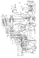
- a side pull mark 1 is shown on the right side of a feed table, not shown.
- a sheet to be aligned is transported approximately perpendicular to the plane 23 of the drawing against a front mark, not shown.
- the right edge of the sheet passes below a swab roller 3 which extends through a shell 2.
- the swab roller 3 is rotatably mounted on a swab roller lever 4 which can be pivoted about an axis 5.
- the pressure exerted by the swab roll 3 on a sheet to be aligned can be preset.
- a by means of an adjusting screw 7 Adaptation to the sheet thickness to be processed in each case shown adjustable shell 2.
- the contact pressure of the swab roller 3 can be varied by turning a threaded sleeve 19.
- a nut 20, which is rotatably arranged on the threaded sleeve 19, is counter-countered.
- a spring rod 18 is guided, on which the compression spring 6 is arranged.
- a curve 15 is fixed so that it rotates with the spindle 25.
- a roller 14 runs on the curved path of curve 15, which causes a swiveling movement of the swab roller lever 4 according to the curve shape about the axis 5 via a guide lever 16 when the spindle 25 rotates.
- the swab roll 3, which is supported in the swab roll lever on a head pin 21, is pressed in the same rhythm against an arc located between the shell 2 and the sliding plate 8.
- the spindle 25 also carries a further curve 22, which is connected to the curve 17 via a guide bush 17 and can be fastened to the sloted guide bush 17 by screws 27.
- the curve stroke and the length of the curve stroke of curve 22 define the control range for the drawing operation, which can be shifted by turning curve 22.
- a roller 11 runs in curve 22,
- the sliding plate 8 is fixed on the slide 29 by at least one fastening screw 9.
- the shape of the curve regions makes it possible to coordinate the time at which the swab roller 3 touches the sliding plate 8 with the pulling movement of the sliding plate 8, so that the sheet located with its right edge between the swab roller 3 and the sliding plate 8 can be pulled against a right stop 28.
- the setting of the curve 22 by twisting on the guide bushing 17 is facilitated by the use of a setting mark 26, the screws 27 connecting the curve 22 to the guide bushing 17 having to be loosened for the setting process.
- the sliding plate 8 has suction openings 30 which can be acted upon by suction air via a vacuum chamber 31. Air is sucked out of the vacuum chamber 31 via a connecting piece 32 and a flexible line 33.
- the flexible line 33 is connected to a control valve 34, with the aid of which the vacuum conducted via a line 35 can be timed.
- the strength of the vacuum can be adjusted by a pressure reducing device 36.
- the vacuum is generated via a suction line 37 with a vacuum source, not shown.
- At least one clock disk 38 is arranged on the spindle 25 or another single-turn shaft. By loosening the fastening screws 39 and 40, the clock disk 38 can be brought into the desired circumferential position and then fixed.
- the clock disc 38 has a circumferential direction extending recess between the control edges 41 and 42. This recess extends over the area during which the suction air is to take effect.
- a sensing element in the form of an electrical sensor switch 43 is shown schematically, which can be fixed at a suitable point on the system table.
- the switch 43 engages with its legs 44 and 45 the clock disc 38 and generates when the first control edge occurs, for. B. 41, until the appearance of the second control edge, for. B. 42, an electrical signal through which the suction air supply to the suction openings 30 in the slide plate 8 in the control valve 34 is released.
- the control valve 34 blocks the suction air supply to the suction openings 30. This blocking can be effected in a known manner by interrupting the supply path or by establishing a connection to the atmosphere, through which the vacuum breaks down.
- the vacuum supply via the control valve 34 to the suction openings 30 coincides with the initial pulling movement of the sliding plate 8 interacting with the swab roller 3, so that the sheet to be pulled against the stop 28 is accelerated very quickly, with the swab roller 3 the sheet in each case against the Suction openings 30 is pressed so that they can be completely covered and no incorrect air can arise.
- the force of the suction air exerted on the pressure carrier supports the pulling movement of the swab roller 3 and the sliding plate 8, so that despite the existing one relatively Great liability of the sheet at the beginning of the drawing process, which can be accelerated quickly.
- the vacuum is switched off again after the recess 41, 42 has overrun and the swab roller 3 and the sliding plate 8 pull the sheet to be aligned against the stop 28 with reduced tensile force As a result, the risk of upsetting and rebounding against the stop 28 is substantially reduced or eliminated. Due to the suction air support during the acceleration phase, it is possible to reduce the presettable pressure of the swab roller 3 against the sliding plate 8, so that in the last phase of the drawing process it is possible to switch to a sliding movement. This in turn prevents the arch from forming waves after it reaches the stop 28.
- the suction air can thus support the drawing movement at a specific time and for a specific duration.
- the intensity with which the suction air acts on the sheet to be aligned can be set by the pressure reducing device 36.
- control valve 34 can be controlled by means of an adjustable timer by means of electronic means when the recess is detected, ie when the first control edge occurs.
- a further clock disk 46 in this case, to be arranged next to the clock disc 38 on the spindle 25.
- the dimension of the recess extending in the circumferential direction can thus be changed by relative rotation between the clock disk 38 and the clock disk 46 shown in broken lines.
Landscapes
- Engineering & Computer Science (AREA)
- Mechanical Engineering (AREA)
- Sheets, Magazines, And Separation Thereof (AREA)
- Registering Or Overturning Sheets (AREA)
Applications Claiming Priority (2)
| Application Number | Priority Date | Filing Date | Title |
|---|---|---|---|
| DE3011626 | 1980-03-26 | ||
| DE19803011626 DE3011626A1 (de) | 1980-03-26 | 1980-03-26 | Vorrichtung zum seitlichen ausrichten von selbsttaetig zugefuehrten bogen an druckmaschinen |
Publications (2)
| Publication Number | Publication Date |
|---|---|
| EP0036496A1 true EP0036496A1 (fr) | 1981-09-30 |
| EP0036496B1 EP0036496B1 (fr) | 1984-05-09 |
Family
ID=6098353
Family Applications (1)
| Application Number | Title | Priority Date | Filing Date |
|---|---|---|---|
| EP81101332A Expired EP0036496B1 (fr) | 1980-03-26 | 1981-02-25 | Dispositif pour un ajustage latéral de feuilles amenées automatiquement pour machines à imprimer |
Country Status (3)
| Country | Link |
|---|---|
| EP (1) | EP0036496B1 (fr) |
| JP (1) | JPS56150552A (fr) |
| DE (2) | DE3011626A1 (fr) |
Cited By (2)
| Publication number | Priority date | Publication date | Assignee | Title |
|---|---|---|---|---|
| EP0161507A1 (fr) * | 1984-05-12 | 1985-11-21 | Heidelberger Druckmaschinen Aktiengesellschaft | Dispositif d'alimentation pour machines traitant des feuilles, notamment machines à imprimer |
| KR101138325B1 (ko) * | 2004-10-06 | 2012-04-25 | 어시스트 메디칼 시스템즈, 인크. | 의료 촬영 과정의 일부로서 조영제를 투여하기 전에 환자의 신장 기능을 평가하기 위한 의료 촬영 시스템 및 컴퓨터 프로그램 제품 |
Families Citing this family (7)
| Publication number | Priority date | Publication date | Assignee | Title |
|---|---|---|---|---|
| DE3219653C1 (de) * | 1982-05-26 | 1984-01-26 | Heidelberger Druckmaschinen Ag, 6900 Heidelberg | Vorrichtung zur Kontrolle der seitlichen Bogenanlage sowie zur Unterbrechung der Bogenzufuehrung bei fehlerhafter seitlicher Bogenanlage |
| DE4118174C2 (de) * | 1991-06-03 | 2001-05-10 | Koenig & Bauer Ag | Vorrichtung zum seitlichen Ausrichten von Bogen |
| DE4242731A1 (de) * | 1992-12-17 | 1994-06-23 | Heidelberger Druckmasch Ag | Vorrichtung zum seitlichen Ausrichten von Bogen in Druckmaschinen |
| JP4723053B2 (ja) * | 1999-03-19 | 2011-07-13 | ハイデルベルガー ドルツクマシーネン アクチエンゲゼルシヤフト | 横引き寄せ装置の負圧レベルを制御する方法および装置 |
| DE10233148A1 (de) | 2001-08-30 | 2003-03-20 | Heidelberger Druckmasch Ag | Vorrichtung zum seitlichen Ausrichten von Bogen an bogenverarbeitenden Maschinen, insbesondere Druckmaschinen |
| JP4435554B2 (ja) | 2003-12-17 | 2010-03-17 | リョービ株式会社 | 印刷機の給紙部における紙位置決め装置 |
| CN110271270B (zh) * | 2019-07-11 | 2023-08-15 | 江苏华宇印涂设备集团有限公司 | 一种涂布印刷机侧规装置 |
Citations (1)
| Publication number | Priority date | Publication date | Assignee | Title |
|---|---|---|---|---|
| DE2901188A1 (de) * | 1978-04-19 | 1979-10-31 | Polygraph Leipzig | Einrichtung zum ausrichten von bogen in bogenverarbeitenden maschinen |
-
1980
- 1980-03-26 DE DE19803011626 patent/DE3011626A1/de not_active Withdrawn
-
1981
- 1981-02-25 DE DE8181101332T patent/DE3163453D1/de not_active Expired
- 1981-02-25 EP EP81101332A patent/EP0036496B1/fr not_active Expired
- 1981-03-26 JP JP4327681A patent/JPS56150552A/ja active Granted
Patent Citations (1)
| Publication number | Priority date | Publication date | Assignee | Title |
|---|---|---|---|---|
| DE2901188A1 (de) * | 1978-04-19 | 1979-10-31 | Polygraph Leipzig | Einrichtung zum ausrichten von bogen in bogenverarbeitenden maschinen |
Cited By (2)
| Publication number | Priority date | Publication date | Assignee | Title |
|---|---|---|---|---|
| EP0161507A1 (fr) * | 1984-05-12 | 1985-11-21 | Heidelberger Druckmaschinen Aktiengesellschaft | Dispositif d'alimentation pour machines traitant des feuilles, notamment machines à imprimer |
| KR101138325B1 (ko) * | 2004-10-06 | 2012-04-25 | 어시스트 메디칼 시스템즈, 인크. | 의료 촬영 과정의 일부로서 조영제를 투여하기 전에 환자의 신장 기능을 평가하기 위한 의료 촬영 시스템 및 컴퓨터 프로그램 제품 |
Also Published As
| Publication number | Publication date |
|---|---|
| EP0036496B1 (fr) | 1984-05-09 |
| DE3163453D1 (en) | 1984-06-14 |
| JPH025652B2 (fr) | 1990-02-05 |
| JPS56150552A (en) | 1981-11-21 |
| DE3011626A1 (de) | 1981-10-01 |
Similar Documents
| Publication | Publication Date | Title |
|---|---|---|
| DE3215804C2 (de) | Bogenanlegetisch für eine Bogenrotationsdruckmaschine | |
| EP1055622B2 (fr) | Dispositif de contrôle pour feuilles superposées | |
| DE4011286C2 (fr) | ||
| EP0213397B1 (fr) | Pince à ressort pour rotatives à feuille | |
| EP0036496B1 (fr) | Dispositif pour un ajustage latéral de feuilles amenées automatiquement pour machines à imprimer | |
| DE19600793C2 (de) | Vorrichtung zum Ausrichten von Bogen auf dem Anlegetisch einer Bogendruckmaschine | |
| DE4340858A1 (de) | Zylinder | |
| DE4230218C2 (de) | Vorgreifer einer Bogendruckmaschine | |
| EP0309815B1 (fr) | Dispositif pour amener des feuilles à une machine de traitement de feuilles, notamment à une imprimeuse | |
| DE3114581C2 (de) | Fördervorrichtung für eine Bogen-Rotationsdruckmaschine | |
| DE19804039A1 (de) | Sauggreifer zur Übergabe der Hinterkante eines Bogens in einer Wendeeinrichtung einer Bogenrotationsdruckmaschine | |
| DE19962116A1 (de) | Leitvorrichtung zum Führen von Bogen und Verfahren zum Betreiben einer Leitvorrichtung | |
| DE2127757B2 (de) | Fehlbogen-Abtast- und Steuervorrichtung | |
| EP0679593B1 (fr) | Rouleau à mouvement cadencé pour transporter des feuilles dans un machine d'impression | |
| EP0161507B1 (fr) | Dispositif d'alimentation pour machines traitant des feuilles, notamment machines à imprimer | |
| DE2836098A1 (de) | Umstellbare schoen- und widerdruck - bogenoffset-rotationsmaschine mit gummiauf-gummi - druckwerk und vorrichtung zum passgenauen einfuehren der bogen in das druckwerk | |
| DE1786196A1 (de) | Verfahren und Vorrichtung zur Papierblatteinstellung bei Druckmaschinen | |
| DE10244219B4 (de) | Vorrichtung und Verfahren zur Bogenzufuhr an eine Bogenverarbeitende Maschine, insbesondere Druckmaschine | |
| DE2929583C2 (de) | Zieh- und Schiebemarke | |
| EP0282828A1 (fr) | Lissoir pour feuilles dans la zone d'alimentation d'une machine à traitement de feuilles | |
| EP1935817A2 (fr) | Dispositif de guidage destiné à l'introduction de feuilles dans une machine d'imprimerie | |
| DE10024018B4 (de) | Vorrichtung zum Bilden eines Bogenstroms von sich schuppenartig teilweise überdeckenden Bogen | |
| EP1334828B1 (fr) | Dispositif pour aligner latéralement des feuilles | |
| DE4407505C2 (de) | Einrichtung zur Bogenausrichtung und -vereinzelung an der Oberseite eines Bogenstapels | |
| DE19642483A1 (de) | Druckmaschine mit Bogenanlager |
Legal Events
| Date | Code | Title | Description |
|---|---|---|---|
| PUAI | Public reference made under article 153(3) epc to a published international application that has entered the european phase |
Free format text: ORIGINAL CODE: 0009012 |
|
| AK | Designated contracting states |
Designated state(s): CH DE FR GB IT |
|
| 17P | Request for examination filed |
Effective date: 19811014 |
|
| ITF | It: translation for a ep patent filed | ||
| GRAA | (expected) grant |
Free format text: ORIGINAL CODE: 0009210 |
|
| AK | Designated contracting states |
Designated state(s): CH DE FR GB IT LI |
|
| REF | Corresponds to: |
Ref document number: 3163453 Country of ref document: DE Date of ref document: 19840614 |
|
| ET | Fr: translation filed | ||
| PLBE | No opposition filed within time limit |
Free format text: ORIGINAL CODE: 0009261 |
|
| STAA | Information on the status of an ep patent application or granted ep patent |
Free format text: STATUS: NO OPPOSITION FILED WITHIN TIME LIMIT |
|
| 26N | No opposition filed | ||
| PG25 | Lapsed in a contracting state [announced via postgrant information from national office to epo] |
Ref country code: LI Effective date: 19860228 Ref country code: CH Effective date: 19860228 |
|
| REG | Reference to a national code |
Ref country code: CH Ref legal event code: PL |
|
| PGFP | Annual fee paid to national office [announced via postgrant information from national office to epo] |
Ref country code: FR Payment date: 19910116 Year of fee payment: 11 |
|
| PGFP | Annual fee paid to national office [announced via postgrant information from national office to epo] |
Ref country code: GB Payment date: 19910117 Year of fee payment: 11 Ref country code: DE Payment date: 19910117 Year of fee payment: 11 |
|
| ITTA | It: last paid annual fee | ||
| PG25 | Lapsed in a contracting state [announced via postgrant information from national office to epo] |
Ref country code: GB Effective date: 19920225 |
|
| GBPC | Gb: european patent ceased through non-payment of renewal fee | ||
| PG25 | Lapsed in a contracting state [announced via postgrant information from national office to epo] |
Ref country code: FR Effective date: 19921030 |
|
| PG25 | Lapsed in a contracting state [announced via postgrant information from national office to epo] |
Ref country code: DE Effective date: 19921103 |
|
| REG | Reference to a national code |
Ref country code: FR Ref legal event code: ST |