EP0036610B1 - Procédé de fonctionnement d'une source de chaleur chauffée par combustible - Google Patents
Procédé de fonctionnement d'une source de chaleur chauffée par combustible Download PDFInfo
- Publication number
- EP0036610B1 EP0036610B1 EP81101963A EP81101963A EP0036610B1 EP 0036610 B1 EP0036610 B1 EP 0036610B1 EP 81101963 A EP81101963 A EP 81101963A EP 81101963 A EP81101963 A EP 81101963A EP 0036610 B1 EP0036610 B1 EP 0036610B1
- Authority
- EP
- European Patent Office
- Prior art keywords
- valve
- fuel
- shut
- heat source
- pressure
- Prior art date
- Legal status (The legal status is an assumption and is not a legal conclusion. Google has not performed a legal analysis and makes no representation as to the accuracy of the status listed.)
- Expired
Links
Images

Classifications
-
- F—MECHANICAL ENGINEERING; LIGHTING; HEATING; WEAPONS; BLASTING
- F23—COMBUSTION APPARATUS; COMBUSTION PROCESSES
- F23N—REGULATING OR CONTROLLING COMBUSTION
- F23N1/00—Regulating fuel supply
- F23N1/06—Regulating fuel supply conjointly with draught
- F23N1/067—Regulating fuel supply conjointly with draught using mechanical means
-
- F—MECHANICAL ENGINEERING; LIGHTING; HEATING; WEAPONS; BLASTING
- F23—COMBUSTION APPARATUS; COMBUSTION PROCESSES
- F23N—REGULATING OR CONTROLLING COMBUSTION
- F23N2235/00—Valves, nozzles or pumps
- F23N2235/02—Air or combustion gas valves or dampers
- F23N2235/04—Air or combustion gas valves or dampers in stacks
-
- F—MECHANICAL ENGINEERING; LIGHTING; HEATING; WEAPONS; BLASTING
- F23—COMBUSTION APPARATUS; COMBUSTION PROCESSES
- F23N—REGULATING OR CONTROLLING COMBUSTION
- F23N2235/00—Valves, nozzles or pumps
- F23N2235/12—Fuel valves
- F23N2235/14—Fuel valves electromagnetically operated
-
- F—MECHANICAL ENGINEERING; LIGHTING; HEATING; WEAPONS; BLASTING
- F23—COMBUSTION APPARATUS; COMBUSTION PROCESSES
- F23N—REGULATING OR CONTROLLING COMBUSTION
- F23N2235/00—Valves, nozzles or pumps
- F23N2235/12—Fuel valves
- F23N2235/18—Groups of two or more valves
-
- F—MECHANICAL ENGINEERING; LIGHTING; HEATING; WEAPONS; BLASTING
- F23—COMBUSTION APPARATUS; COMBUSTION PROCESSES
- F23N—REGULATING OR CONTROLLING COMBUSTION
- F23N2235/00—Valves, nozzles or pumps
- F23N2235/12—Fuel valves
- F23N2235/20—Membrane valves
-
- F—MECHANICAL ENGINEERING; LIGHTING; HEATING; WEAPONS; BLASTING
- F23—COMBUSTION APPARATUS; COMBUSTION PROCESSES
- F23N—REGULATING OR CONTROLLING COMBUSTION
- F23N2235/00—Valves, nozzles or pumps
- F23N2235/12—Fuel valves
- F23N2235/24—Valve details
Definitions
- the present invention relates to a method for operating a fuel-heated heat source according to the preamble of the claim.
- DE-A-3 007 214 which is not part of the prior art, has disclosed a fitting for controlling the operating behavior of a fuel-heated heat source, in which a servo pressure is specified via a diaphragm pump, which acts on a regulator diaphragm which is directly connected to a fuel valve is.
- the greater the variable servo pressure applied to the diaphragm pump the greater the degree of opening of the fuel valve.
- the fuel-heated heat source according to the older patent application, however, it is now not intended to shut off the heat source itself on the supply or exhaust side by means of a shut-off device, and it is also not intended to monitor the position of this shut-off device.
- the present invention is therefore based on the object of keeping the ratio of supplied air and fuel constant from the ignition process to full load.
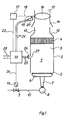
- a heat source 1 has a housing 2, in the interior 3 of which a lamella heat exchanger 4 is provided.
- the housing 2 has at its lower end 5 an inlet air opening, in the area of which a gas burner 6 is arranged, which has a plurality of injectors 7, which is fed by a corresponding plurality of gas nozzles 8 from a gas line 10 provided with a gas valve 9.
- the gas valve 9 is actuated by an actuator 11, the gas valve can assume a closed position and a maximum opening position as well as any possible intermediate position.
- the housing merges into an exhaust duct 13, which is provided with a flow safety device 14, which is followed by an exhaust pipe 15, in which there is a shut-off element 16, which can be rotated by a motor 17 via an actuating shaft 18 from a closed position over a possible variety of opening positions up to a maximum opening position.
- a cam 19 is attached to the shaft 18, which is adjusted relative to the shut-off element 16 in such a way that in an over-ignition position of the cams 19 actuates a contact of a microswitch 20 which is connected to a control device 22 via lines 21.
- the over-ignition position is to be understood as the position of the shut-off element of the gas valve 9 in which so much gas reaches the burner that the burner generates flames at all combustion slots.
- the associated position of the exhaust flap must cause the combustion gas generated to be removed after passing through the heat exchanger, without too much air being sucked in at the lower end 5 of the housing 2 by the suction effect in the exhaust duct 15 and being transported through the heat exchanger.
- the control device 22 is connected via a control line 23 to the motor 17 and via a control line 24 to the servomotor 11.
- Measuring lines 25 lead to a temperature sensor 26, which is arranged in a recess 27 on the side casing of the housing 2 approximately halfway between the burner and the heat exchanger. The sensor 26 is at a distance from the opening.
- Connections 28 serve to supply the control device from a power supply unit.
- the control device 22 is the individual subject of FIG. 2: It has a housing 30 which has an inlet chamber 31 and an outlet chamber 32 in the course of the gas line 10. Between the inlet and outlet chamber there is a valve seat 33 which can be closed in the idle state by a valve body 9 which is articulated by a rod 34 and which is under the restoring force of a compression spring 36, the continuous rod 34 with a diaphragm plate 37 being a rule Membrane 11 is connected, which is clamped pressure-tight in the housing 30 in the region of the outlet chamber 32 at its edge.
- the inlet and outlet chambers are thus separated from one another in the idle state via the closed valve 33, 9.
- the membrane divides a further chamber 39, which leads via a channel 40 to a valve center space 41.
- the valve center space 41 is delimited by two valve seats 42 and 43 and an outflow opening 44.
- a pilot gas line 35 branches off from the gas line 10 and leads to a pilot burner (not shown). Furthermore, in the course of the gas line 10, also upstream of the inlet chamber 31, a valve seat 38 is provided which is controlled by a valve body 100. This valve body is controlled by a compression spring 101, which is supported with respect to the housing 30. An actuating rod 102 engages on the valve body 100 and leads to a water switch 103, the housing of which is firmly connected to the housing 30. The inside of the water switch has a membrane 104 which is engaged by a membrane plate 105 which is connected to the rod 102.
- the two pressure chambers divided by the membrane 104 in the interior of the water switch are connected to a flow pressure sensor in the circulation circuit of the water heater or in the tap water path of the water heater, the water switch 103 forms, together with the valve 100/38, a lack of water protection.
- a channel 45 leads from the valve seat 43 to a branching point 46, from which a further channel 47 leads to the outlet chamber 32.
- Another channel 48 leads to a membrane chamber 49, which is connected to the outflow opening 44 via a line 50, in which a valve seat 51 is provided.
- a valve body 52 corresponds to the valve seat 51, which can be moved in the open position by a compression spring 53 which is supported with respect to the housing 30.
- the valve body 52 is applied to a membrane 54 which is under the action of a compression spring 55 which is actuated by an adjusting screw 56 Is adjustable, which in turn is gastight in a thread in the housing 30.
- a further membrane chamber 57 is formed, which is connected via an opening 58 to a further membrane chamber 59.
- this membrane chamber is delimited by a membrane 60, which forms a further membrane chamber 61 on the side facing away from the membrane chamber 59, in which a compression spring 62 is mounted, which is supported against an adjusting screw 63, which is gas-tight in one in the housing Thread is guided.
- the membrane chamber 61 is connected to the atmosphere via a calibrated bore 64.
- a valve body 74 which corresponds to a valve seat 75 arranged in the housing 30, is applied to the membrane 60.
- the valve seat 75 is connected to the membrane chamber 59 via a line 76.
- the valve body 74 is under the action of a compression spring 77, which is supported with respect to the housing 30 and tends to lift the valve body 74 from its valve seat 75.
- the valve seat 75 is adjoined by a chamber 78, which is connected to the membrane chamber 59 via a bore 79 of relatively small cross-section and via an air filter bore 80 to the atmosphere via an air filter 81.
- the chamber 78 Via a suction line 82, the chamber 78 is connected to the suction port of a diaphragm pump 83, which is driven by a motor 73, not shown, via a shaft 84.
- the motor in turn, can be supplied with voltage or electrical power by an actuator in order to ensure a certain drive behavior of the motor.
- the diaphragm pump has a pressure line 85 from which the actuating line 23 branches off.
- the pressure line 85 is connected to the diaphragm chamber 59 via a throttle bore 86.
- the valve seat 42 is controlled by a valve body 65 which is connected to an actuating rod 66.
- a two-armed lever 67 which is rotatably mounted about a pivot point 68 in the housing, engages on the adjusting rod 66.
- a return spring 69 brings the lever into the rest position shown and ensures that the valve body 65 rests on the valve seat 42 in the idle state.
- An electromagnet 70 which cooperates with an armature 71, which is part of the two-armed lever 67, is fastened to the housing 30.
- the electromagnet 70 can be supplied with electrical energy via a line 72.
- the line 23 leads to a housing 87 in which the servomotor 17 and a further servomotor 88 with a membrane 109 and an actuating pin 110 acting on the lever 94 are arranged.
- the servomotor 17 has two pressure chambers 89 and 90 within the housing 87, which are separated by a diaphragm 91 which is connected to a diaphragm plate 92 to which an actuating rod 93 engages, which is connected to a two-armed lever 94 which is connected to one Pivot 95 is rotatable.
- a compression spring 96 is used for resetting, it is supported against the housing 30.
- the pivot point 95 can be located on the housing 30.
- the lever 94 has on one end a toothing 97 which cooperates with a gear 98, the gear 98 being fixed on the shaft 18.
- the toothing 97 thus forms the one lever arm 99 of the lever 94.
- the other lever arm 106 is connected to the adjusting rod 93 and has the cam 19 at its end.
- the electromagnet 70 is arranged in a space 107 which is connected to the inlet chamber 31 via a bore 108.
- the control device just described has the following function: starting from the idle state shown in the drawing, the valve seat 33 is ver through the valve body 9 under the expansion effect of the compression spring 36 closed, that is, the connection between the gas inlet and gas outlet is interrupted.
- the diaphragm pump 83 is in the rest position, pressure and suction lines 85 and 82 do not have any differential pressure with respect to one another.
- the valves 42/65, 52/51 and 74/75 are closed, the electromagnet 70 is de-energized.
- the gas supply to the burner 6 is interrupted.
- the electromagnet 70 is supplied with electrical voltage via the line 72. This leads to a lifting of the valve body 65 from the valve seat 42.
- the pressure is also present via the opened valve 65/42 and the channel 40 in the chamber 39, so that the membrane 11 rises against the restoring force of the spring 36 and thus raises the valve body 9 from the valve seat 33.
- This lifting position of the valve body 9 leads to the so-called over-ignition position, here so much gas is passed through the gas line 10 that the connected burner of the heat source forms flames at all combustion slots. Due to the backflow effect of the combustion slots, the gas pressure of the chamber 32 is present via the line 10 in the membrane chamber 89, so that the membrane 91 is lifted against the restoring force of the spring 96 and the lever 94 is pivoted about the pivot point 95. This pivoting movement leads to a deflection of the shut-off valve 16, which changes from its closed position to the over-ignition position. This ignition position is exclusively dependent on the gas pressure behind the fitting 22.
- the cam 19 acts on the microswitch 20, so that the motor 73 of the diaphragm pump can only be energized after the ignition position has been reached.
- the actuation of the microswitch 20 also has the consequence that the heating element of a bimetallic safety switch (both not shown), which was also switched on when heat was requested, is again disconnected from the voltage.
- the bimetallic safety switch controls the power supply to the magnet 70 and to the diaphragm pump motor 73, so that the associated opening position of the shut-off device 16 is also monitored.
- the pressure supplied by the diaphragm pump is limited by the diaphragm 60, which is movable against the restoring force of the spring 62. If the pressure in the diaphragm chamber 59 exceeds the limit value, the diaphragm 60 pulls the valve body 74 off its seat 75 and short-circuits the suction and pressure side of the diaphragm pump. This valve 74/75 acts in conjunction with the membrane 60 as a maximum pressure limiter.
- the pressure in the membrane chamber 59 is also present in the membrane chamber 57. An increasing air pressure there leads to a throttling of the valve 52/51.
- valve body 65 Since the valve body 65 already rests on the valve seat 43, closing the valve body 52 causes a load on the membrane chamber 39, so that the valve body 9 moves in the direction of opening the valve seat 33.
- the valve 52/51 thus acts in conjunction with the membrane 54 as a continuous setpoint generator for the gas throughput.
- the tracking of the exhaust flap in a gas throughput mode between the maximum output and the overfiring output is monitored by the temperature sensor 26: If the shut-off element has an opening position that is smaller than the corresponding gas throughput to achieve optimal combustion or an optimal air excess, the interior sinks 3 of the heat source 1 of the exhaust gas level and exhaust gas escaping causes the temperature sensor 26 to respond. A response of the temperature sensor 26 leads to a lockout via the control device 22.
- the motor 73 of the diaphragm pump 83 is de-energized. This leads to the pressure line 85 becoming depressurized and the shut-off valve 16 turning back until the over-ignition position is reached. Furthermore, this leads to the fact that only the over-ignition gas throughput reaches the burner through the valve 9/33. If the device is now to be shut down completely, the operating voltage is removed from line 72. As a result, the electromagnet 70 is de-energized, so that the valve body 65 lifts off the valve seat 43 and closes the valve seat 42. As a result, the diaphragm chamber 39 is depressurized, so that the spring 36 pulls the valve body fully into the closed position on the seat 33.
- the gas supply is thus interrupted, the depressurization of the gas line 10 behind the armature 22 leads to a resetting of the diaphragm 91 due to the restoring force of the spring 96.
- the cam 19 thus leaves the microswitch 20 and the exhaust flap 16 goes into the closed position. The device has gone out.
Landscapes
- Engineering & Computer Science (AREA)
- Chemical & Material Sciences (AREA)
- Combustion & Propulsion (AREA)
- Mechanical Engineering (AREA)
- General Engineering & Computer Science (AREA)
- Feeding And Controlling Fuel (AREA)
- Control Of Combustion (AREA)
- Air-Conditioning For Vehicles (AREA)
Claims (1)
- Mode de fonctionnement commandant la marche d'une source calorifique (1) avec un brûleur (6) alimenté par une soupape (9), un échangeur de chaleur (4) ainsi qu'un organe de fermeture (16) commandé par un dispositif de commande et de réglage (22) et réglant le flux d'air et de gaz de combustion traversant la source calorifique, caractérisé par le fait que le passage de l'organe de fermeture (16) depuis la position de fermeture dans la position d'allumage du brûleur est commandé par la pression du combustible et que dans cette position de cet organe, la soupape de combustible (9) est ouverte plus largement et que les variations de la position de l'organe de fermeture depuis la position d'allumage jusqu'à la position d'ouverture maximale sont commandées par une servo-pression (83, 85) qui en même temps détermine la position de la soupape de combustible (9), et que la position d'ouverture maximale de l'organe de fermeture est contrôlée par une sonde thermométrique (26) qui réagit aux niveaux des gaz de combustion dans la source calorifique (1 ).
Priority Applications (1)
| Application Number | Priority Date | Filing Date | Title |
|---|---|---|---|
| AT81101963T ATE12828T1 (de) | 1980-03-25 | 1981-03-17 | Verfahren zum betreiben einer brennstoffbeheizten waermequelle. |
Applications Claiming Priority (2)
| Application Number | Priority Date | Filing Date | Title |
|---|---|---|---|
| DE8008123 | 1980-03-25 | ||
| DE8008123U | 1980-03-25 |
Publications (3)
| Publication Number | Publication Date |
|---|---|
| EP0036610A2 EP0036610A2 (fr) | 1981-09-30 |
| EP0036610A3 EP0036610A3 (en) | 1981-11-25 |
| EP0036610B1 true EP0036610B1 (fr) | 1985-04-17 |
Family
ID=6714112
Family Applications (1)
| Application Number | Title | Priority Date | Filing Date |
|---|---|---|---|
| EP81101963A Expired EP0036610B1 (fr) | 1980-03-25 | 1981-03-17 | Procédé de fonctionnement d'une source de chaleur chauffée par combustible |
Country Status (2)
| Country | Link |
|---|---|
| EP (1) | EP0036610B1 (fr) |
| AT (1) | ATE12828T1 (fr) |
Families Citing this family (3)
| Publication number | Priority date | Publication date | Assignee | Title |
|---|---|---|---|---|
| EP0103303A3 (fr) * | 1982-09-15 | 1984-06-06 | Joh. Vaillant GmbH u. Co. | Source de chaleur chauffée au combustible |
| HU230446B1 (hu) * | 2010-04-15 | 2016-06-28 | Lajos Tamás Pólya | Gázfogyasztást csökkentő szerkezet, egyedi gázfűtő készülékekhez, elsősorban gázkonvektorokhoz és gázkandallókhoz |
| IT1403351B1 (it) * | 2010-12-21 | 2013-10-17 | Sit La Precisa Spa Con Socio Unico | Dispositivo per il controllo dell'erogazione di un gas combustibile verso un bruciatore, particolarmente per apparecchi riscaldatori di acqua |
Family Cites Families (5)
| Publication number | Priority date | Publication date | Assignee | Title |
|---|---|---|---|---|
| US4084743A (en) * | 1976-09-27 | 1978-04-18 | Johnson Controls, Inc. | Interlock arrangement for a stack damper control |
| US4164936A (en) * | 1977-08-18 | 1979-08-21 | Dottore Jr Nicholas J | Damper |
| US4185769A (en) * | 1977-09-12 | 1980-01-29 | Nezworski James E | Exhaust flue damper and control system therefor |
| US4189296A (en) * | 1978-03-13 | 1980-02-19 | Johnson Controls, Inc. | Method and apparatus for controlling furnace |
| DE3007214C2 (de) * | 1979-03-10 | 1983-11-10 | Joh. Vaillant Gmbh U. Co, 5630 Remscheid | Gasdruckregler für einen gasbeheizten Umlaufwasserheizer mit einem Gebrauchswasserbereiter |
-
1981
- 1981-03-17 EP EP81101963A patent/EP0036610B1/fr not_active Expired
- 1981-03-17 AT AT81101963T patent/ATE12828T1/de not_active IP Right Cessation
Also Published As
| Publication number | Publication date |
|---|---|
| ATE12828T1 (de) | 1985-05-15 |
| EP0036610A3 (en) | 1981-11-25 |
| EP0036610A2 (fr) | 1981-09-30 |
Similar Documents
| Publication | Publication Date | Title |
|---|---|---|
| DE19722600C2 (de) | Servoregler | |
| EP0957314B1 (fr) | Dispositif de commande pour des brûleurs à gaz | |
| DE2749252C3 (de) | Betätigungsvorrichtung für die Verstellung des Verschlußstücks eines Ventils | |
| EP0390964B1 (fr) | Dispositif de commande pour brûleur à gaz | |
| EP0036610B1 (fr) | Procédé de fonctionnement d'une source de chaleur chauffée par combustible | |
| DE1802413A1 (de) | Stroemungsmittel-Steuereinrichtung | |
| DE1628228B2 (de) | Regelvorrichtung fuer einen verdichter | |
| EP0035147B1 (fr) | Régulateur de pression à gaz | |
| EP0016326B1 (fr) | Régulateur de pression du gaz | |
| DE4440492A1 (de) | Durchlauf-Wassererhitzer | |
| DE3011374C2 (fr) | ||
| EP0103303A2 (fr) | Source de chaleur chauffée au combustible | |
| DE2723178C2 (de) | Sicherheits- und Steuersystem für die Luftzufuhr zur Verbrennungskammer eines Gasbrenners mit Zwangsabzug | |
| DE3007214C2 (de) | Gasdruckregler für einen gasbeheizten Umlaufwasserheizer mit einem Gebrauchswasserbereiter | |
| DE3114942A1 (de) | Regeleinrichtung fuer den gasbefeuerten heizkessel einer warmwasser-heizungsanlage | |
| DE3333606A1 (de) | Brennstoffbeheizte waermequelle | |
| DE3000669C2 (de) | Gasdruckregler | |
| DE3007215C2 (de) | Gasdruckregler für einen gasbeheizten Umlaufwasserheizer mit einem Brauchwasserbereiter | |
| DE3339518C2 (de) | Gasbeheizte Wärmequelle | |
| EP0036613A1 (fr) | Dispositif de régulation pour un échauffeur à eau ou air à combustion gazeuse pouvant être commandé par un capteur de température | |
| DE1075896B (de) | Regler fuer Gasturbinen | |
| EP0013993B1 (fr) | Régulateur de pression | |
| EP0108349A2 (fr) | Source de chaleur chauffée au gaz | |
| DE2630414A1 (de) | Einrichtung zum steuern der luftzufuhr zu einer geschlossenen feuerstelle | |
| DE3010737A1 (de) | Gasregelgeraet fuer brenner |
Legal Events
| Date | Code | Title | Description |
|---|---|---|---|
| PUAI | Public reference made under article 153(3) epc to a published international application that has entered the european phase |
Free format text: ORIGINAL CODE: 0009012 |
|
| PUAL | Search report despatched |
Free format text: ORIGINAL CODE: 0009013 |
|
| AK | Designated contracting states |
Designated state(s): AT BE CH FR GB IT LI LU NL SE |
|
| AK | Designated contracting states |
Designated state(s): AT BE CH FR GB IT LI LU NL SE |
|
| 17P | Request for examination filed |
Effective date: 19811102 |
|
| RAP1 | Party data changed (applicant data changed or rights of an application transferred) |
Owner name: VAILLANT GMBH Owner name: SCHONEWELLE B.V. Owner name: VAILLANT LIMITED Owner name: VAILLANT GES.M.B.H Owner name: COFRABEL N.V. Owner name: JOH. VAILLANT GMBH U. CO |
|
| RAP1 | Party data changed (applicant data changed or rights of an application transferred) |
Owner name: VAILLANT GMBH Owner name: SCHONEWELLE B.V. Owner name: VAILLANT LIMITED Owner name: VAILLANT GES.M.B.H Owner name: VAILLANT S.A.R.L Owner name: COFRABEL N.V. Owner name: JOH. VAILLANT GMBH U. CO |
|
| RAP1 | Party data changed (applicant data changed or rights of an application transferred) |
Owner name: VAILLANT GMBH Owner name: SCHONEWELLE B.V. Owner name: VAILLANT LTD. Owner name: VAILLANT GES.M.B.H Owner name: VAILLANT S.A.R.L Owner name: COFRABEL N.V. Owner name: JOH. VAILLANT GMBH U. CO |
|
| ITF | It: translation for a ep patent filed | ||
| GRAA | (expected) grant |
Free format text: ORIGINAL CODE: 0009210 |
|
| AK | Designated contracting states |
Designated state(s): AT BE CH FR GB IT LI LU NL SE |
|
| REF | Corresponds to: |
Ref document number: 12828 Country of ref document: AT Date of ref document: 19850515 Kind code of ref document: T |
|
| ET | Fr: translation filed | ||
| PLBE | No opposition filed within time limit |
Free format text: ORIGINAL CODE: 0009261 |
|
| STAA | Information on the status of an ep patent application or granted ep patent |
Free format text: STATUS: NO OPPOSITION FILED WITHIN TIME LIMIT |
|
| PGFP | Annual fee paid to national office [announced via postgrant information from national office to epo] |
Ref country code: AT Payment date: 19860326 Year of fee payment: 6 |
|
| 26N | No opposition filed | ||
| PG25 | Lapsed in a contracting state [announced via postgrant information from national office to epo] |
Ref country code: AT Effective date: 19870317 |
|
| ITTA | It: last paid annual fee | ||
| PGFP | Annual fee paid to national office [announced via postgrant information from national office to epo] |
Ref country code: SE Payment date: 19921207 Year of fee payment: 13 Ref country code: FR Payment date: 19921207 Year of fee payment: 13 |
|
| PGFP | Annual fee paid to national office [announced via postgrant information from national office to epo] |
Ref country code: LU Payment date: 19921209 Year of fee payment: 13 |
|
| PGFP | Annual fee paid to national office [announced via postgrant information from national office to epo] |
Ref country code: GB Payment date: 19921217 Year of fee payment: 13 |
|
| PGFP | Annual fee paid to national office [announced via postgrant information from national office to epo] |
Ref country code: BE Payment date: 19930208 Year of fee payment: 13 |
|
| EPTA | Lu: last paid annual fee | ||
| PGFP | Annual fee paid to national office [announced via postgrant information from national office to epo] |
Ref country code: CH Payment date: 19930324 Year of fee payment: 13 |
|
| PGFP | Annual fee paid to national office [announced via postgrant information from national office to epo] |
Ref country code: NL Payment date: 19930331 Year of fee payment: 13 |
|
| NLT1 | Nl: modifications of names registered in virtue of documents presented to the patent office pursuant to art. 16 a, paragraph 1 |
Owner name: VAILLANT B.V. TE AMSTERDAM. |
|
| PG25 | Lapsed in a contracting state [announced via postgrant information from national office to epo] |
Ref country code: LU Free format text: LAPSE BECAUSE OF NON-PAYMENT OF DUE FEES Effective date: 19940317 Ref country code: GB Effective date: 19940317 |
|
| PG25 | Lapsed in a contracting state [announced via postgrant information from national office to epo] |
Ref country code: SE Free format text: LAPSE BECAUSE OF NON-PAYMENT OF DUE FEES Effective date: 19940318 |
|
| PG25 | Lapsed in a contracting state [announced via postgrant information from national office to epo] |
Ref country code: LI Effective date: 19940331 Ref country code: CH Effective date: 19940331 Ref country code: BE Effective date: 19940331 |
|
| BERE | Be: lapsed |
Owner name: S.A. VAILLANT N.V. Effective date: 19940331 |
|
| PG25 | Lapsed in a contracting state [announced via postgrant information from national office to epo] |
Ref country code: NL Effective date: 19941001 |
|
| GBPC | Gb: european patent ceased through non-payment of renewal fee |
Effective date: 19940317 |
|
| NLV4 | Nl: lapsed or anulled due to non-payment of the annual fee | ||
| PG25 | Lapsed in a contracting state [announced via postgrant information from national office to epo] |
Ref country code: FR Effective date: 19941130 |
|
| REG | Reference to a national code |
Ref country code: CH Ref legal event code: PL |
|
| REG | Reference to a national code |
Ref country code: FR Ref legal event code: ST |
|
| EUG | Se: european patent has lapsed |
Ref document number: 81101963.7 Effective date: 19941010 |