EP0036614A1 - Bobine d'allumage pour moteurs à combustion, en particulier pour moteurs à allumage électronique, et procédé pour sa fabrication - Google Patents
Bobine d'allumage pour moteurs à combustion, en particulier pour moteurs à allumage électronique, et procédé pour sa fabrication Download PDFInfo
- Publication number
- EP0036614A1 EP0036614A1 EP81101976A EP81101976A EP0036614A1 EP 0036614 A1 EP0036614 A1 EP 0036614A1 EP 81101976 A EP81101976 A EP 81101976A EP 81101976 A EP81101976 A EP 81101976A EP 0036614 A1 EP0036614 A1 EP 0036614A1
- Authority
- EP
- European Patent Office
- Prior art keywords
- fuse
- primary winding
- ignition coil
- winding
- ignition
- Prior art date
- Legal status (The legal status is an assumption and is not a legal conclusion. Google has not performed a legal analysis and makes no representation as to the accuracy of the status listed.)
- Withdrawn
Links
Images


Classifications
-
- F—MECHANICAL ENGINEERING; LIGHTING; HEATING; WEAPONS; BLASTING
- F02—COMBUSTION ENGINES; HOT-GAS OR COMBUSTION-PRODUCT ENGINE PLANTS
- F02P—IGNITION, OTHER THAN COMPRESSION IGNITION, FOR INTERNAL-COMBUSTION ENGINES; TESTING OF IGNITION TIMING IN COMPRESSION-IGNITION ENGINES
- F02P11/00—Safety means for electric spark ignition, not otherwise provided for
- F02P11/02—Preventing damage to engines or engine-driven gearing
-
- H—ELECTRICITY
- H01—ELECTRIC ELEMENTS
- H01F—MAGNETS; INDUCTANCES; TRANSFORMERS; SELECTION OF MATERIALS FOR THEIR MAGNETIC PROPERTIES
- H01F27/00—Details of transformers or inductances, in general
- H01F27/40—Structural association with built-in electric component, e.g. fuse
- H01F27/402—Association of measuring or protective means
- H01F2027/406—Temperature sensor or protection
-
- H—ELECTRICITY
- H01—ELECTRIC ELEMENTS
- H01H—ELECTRIC SWITCHES; RELAYS; SELECTORS; EMERGENCY PROTECTIVE DEVICES
- H01H37/00—Thermally-actuated switches
- H01H37/74—Switches in which only the opening movement or only the closing movement of a contact is effected by heating or cooling
- H01H37/76—Contact member actuated by melting of fusible material, actuated due to burning of combustible material or due to explosion of explosive material
- H01H37/761—Contact member actuated by melting of fusible material, actuated due to burning of combustible material or due to explosion of explosive material with a fusible element forming part of the switched circuit
- H01H2037/762—Contact member actuated by melting of fusible material, actuated due to burning of combustible material or due to explosion of explosive material with a fusible element forming part of the switched circuit using a spring for opening the circuit when the fusible element melts
- H01H2037/763—Contact member actuated by melting of fusible material, actuated due to burning of combustible material or due to explosion of explosive material with a fusible element forming part of the switched circuit using a spring for opening the circuit when the fusible element melts the spring being a blade spring
-
- H—ELECTRICITY
- H01—ELECTRIC ELEMENTS
- H01H—ELECTRIC SWITCHES; RELAYS; SELECTORS; EMERGENCY PROTECTIVE DEVICES
- H01H37/00—Thermally-actuated switches
- H01H37/74—Switches in which only the opening movement or only the closing movement of a contact is effected by heating or cooling
- H01H37/76—Contact member actuated by melting of fusible material, actuated due to burning of combustible material or due to explosion of explosive material
- H01H2037/768—Contact member actuated by melting of fusible material, actuated due to burning of combustible material or due to explosion of explosive material characterised by the composition of the fusible material
-
- H—ELECTRICITY
- H01—ELECTRIC ELEMENTS
- H01H—ELECTRIC SWITCHES; RELAYS; SELECTORS; EMERGENCY PROTECTIVE DEVICES
- H01H37/00—Thermally-actuated switches
- H01H37/74—Switches in which only the opening movement or only the closing movement of a contact is effected by heating or cooling
- H01H37/76—Contact member actuated by melting of fusible material, actuated due to burning of combustible material or due to explosion of explosive material
- H01H37/761—Contact member actuated by melting of fusible material, actuated due to burning of combustible material or due to explosion of explosive material with a fusible element forming part of the switched circuit
Definitions
- the invention relates to an ignition coil for internal combustion engines, in particular an ignition coil with a reduced effective resistance of the primary winding, which is intended for work in an electronic ignition system, and to a method for producing such a coil.
- a protective device of the ignition coil against an excessive rise in temperature of its windings is known by means of a thermal switch built into its interior, which is connected in series with the primary winding.
- the task of this thermal switch is to interrupt a long-lasting current flow leading to the failure of the ignition coil via its primary winding through the contact opening in the event of an excessive temperature rise inside the ignition coil.
- a manufacturing method for the discussed ignition coil is also known, which is based on the fact that the primary winding is wound directly onto the secondary winding wound on the core insulating tube, the so-called winding support. The complete winding created in this way is provided with the magnetically designed core fitted.
- the primary winding is connected in series with the thermal switch and then the free ends of the primary winding and the thermal switch output are connected to the terminals of the low voltage and the free ends of the secondary winding to the terminals of the high voltage in the ignition coil head.
- the assembled complete winding is then fastened together with the magnetic cores, the thermal switch and the ignition coil head in the coil housing, filled with oil and sealed.
- thermal switch cannot be located between the secondary and primary winding of the ignition coil, i.e. where the temperature is highest.
- the thermal switch is usually housed outside the ignition coil windings in the oil-filled interior of the coil so that it takes effect with a certain delay, and in view of this, there may be cases where thermal damage to the coil insulation of the ignition coil occurs before the thermal switch responds.
- Another disadvantage of the thermal switch is the need for its special attachment in the ignition coil housing, which ensures vibration protection for the thermal switch.
- the relatively high cost of the thermal switch results in a corresponding increase in the price of the ignition coil.
- the starter ignition switch did not flow any current through the primary winding of the ignition coil.
- the current only flows through the primary winding when the transmitter control signal causes the ignition system to be brought into the permanent conduction state. In principle, such a signal can only occur when the engine is working.
- the element subject to secondary disturbance in one Damage to the electronic ignition control circuit is the ignition coil. Since, as already mentioned, the damage to the control circuit mentioned above occurs occasionally, the use of an explosion protection device for the ignition coil is appropriate and economically justified, but this need not be a multi-acting protection device, for example the thermal switch described above. A one-time protective device can be completely sufficient, which nevertheless entails the need to change the ignition coil after an ignition system fault.
- the object of the invention is to provide an ignition coil with a one-time explosion protection device, which also has the advantage that it becomes effective immediately after a temperature rise in the ignition coil windings over a permissible limit.
- This object is achieved according to the invention in that it is equipped with a fuse connected in series with the primary winding, which forms an integral part of this primary winding, has contact with this winding at least on one side and is made of a low-melting material, advantageously from an alloy of about 37 % Lead and about 63% tin.
- the ignition coil is equipped with a fuse connected in series with the primary winding, which is made of a low-melting material and forms an integral part of this winding and has contact with the primary winding at least on one side.
- the production of the melting element from a tin-lead alloy has proven to be particularly favorable, for example Contains 37% lead and about 63% tin.
- the fuse is advantageously in the form of a thin tube filled with rosin, preferably with a diameter of 0.5 to 1.0 mm, and is flattened to a thickness which approximates the thickness of the primary winding conductor of the ignition coil connected to it.
- the fuse in one of the embodiments consists of two resilient metal flakes made of phosphor bronze, which are attached to a flake made of an oil and heat-resistant material, the resilient parts of the metal flakes being accommodated in the opening of the flake and in the tensioned state with Schnellot von the composition of about 37% lead and about 63% tin soldered above.
- the fuse according to the invention is expediently accommodated in the space between the secondary winding and the primary winding of the ignition coil, between the turns of the primary winding or between the turns of the primary winding and the insulating tube, the so-called winding support of this winding.
- the invention also includes a method according to the invention for producing the ignition coil, which consists in that the fuse is attached to the secondary winding of the ignition coil wound in a known manner, according to one of the embodiments of the invention, the connections of the fuse being directed in the same direction as the connections of the primary winding, the fuse is coated with an insulating layer and then the primary winding is wound onto the fuse fastened in this way, after which one of the primary winding ends with one of the fuse The ends and the remaining free end of the primary winding and the free fuse end are connected to the low-voltage terminals in the ignition coil head.
- the fuse arrangement between the turns of the primary winding with the only difference that the fuse is fastened between the turns of this winding by interrupting further winding after the winding of some layers of winding, the fuse in the manner mentioned above attached and then winding continues.
- the primary winding of the ignition coil is wound onto a separate insulating tube (winding support), the fuse is attached to this insulating tube.
- the current limited only by the effective resistance of this winding flows through the primary winding of the ignition coil according to the invention, which causes a temperature rise in this winding which is immediately passed on to the fuse adjacent to the primary winding.
- the fuse is melted under the influence of the temperature rise, thereby preventing an explosive loss of tightness of the ignition coil, which is dangerous for the vehicle and the operator.
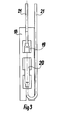
- the primary winding 1 of the ignition coil is connected at one end to the low-voltage terminal 27 and at the other end to the fuse 3.
- the fuse 3 is connected together with the one connection of the secondary winding 4 to the second low-voltage terminal 2.
- the start of the secondary winding 4 is connected to the magnetic core 5 and led out to the outside as an ignition cable connection 6.
- the ignition coil head 8 there is also the connection of the high-voltage circuit in the form of the ignition cable connection 9.
- the high-voltage circuit is brought out to the outside via the inside of the secondary winding 4 attached magnetic core 5, the contact spring 10 and the self-tapping screw 28, which has contact with the ignition cable connection 9 and is screwed into the contact spring 10.
- the magnetic jacket 11 is arranged, which is separated from the primary winding 1 with an insulating cardboard intermediate layer 12.
- the complete winding is separated from the bottom of the ignition coil housing 7 via the insulator 13 made of dielectric material.
- the ignition coil parts located inside the ignition coil housing 7 are immersed in transformer oil 14. The tightness of the ignition coil is ensured by the seals 15 and 16, which are located at the joint of the ignition coil housing 7 with the ignition coil head 8 and at the oil fill opening 17.
- the fuse 3 is shown in the form of a hard tissue plate 18 with three openings 19.
- the alloy wire 20 is made of tin and lead. braided, which consists of 37% lead and 63% tin, is hollow on the inside and filled with rosin.
- the alloy wire 20 is flattened to the thickness of the conductor 21 connected to it.
- the fuse 3 is fastened in the ignition coil between the layers of the primary winding 1.
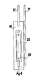
- FIG. 4 An example of another construction of the fuse 3 is shown in FIG. 4.
- An elongated opening 22 is made in the hard tissue plate 18, in the middle of which the fuse 3 is fastened in the form of a flattened alloy wire 20, as was described in the previous example shown in FIG. 3.
- the fuse 3 is in the ignition coil between the insulating tube (winding support) of the primary winding 1 and the primary winding itself arranged.
- FIG. 5 Another example of the fuse 3 according to another variant of the invention is shown in FIG. 5.
- two resilient metal plates 23 and 24 made of phosphor bronze are attached to the hard tissue plate 18.
- the metal leaflets 23 and 24 are soldered together in the tension state using Schnellot 25, which contains 37% lead and 63% tin.
- Resilient parts of the metal plates 23 and 24 are arranged in the opening 26 made in the hard tissue plate 18.
- the ignition coil according to the invention is manufactured in such a way that the fusible link 3 manufactured according to one of the variants of the invention is attached to the secondary winding 4 with adhesive tape in two places. Then the beginning of the primary winding 1 is fastened to the secondary winding 4 with cotton tape and the primary winding 1 is wound onto the fuse 3 covered with an insulating paper layer. After winding the primary winding 1, the beginning of the primary winding 1 is connected to an output of the fuse 3 by twisting and soldering: - The connection point is stripped with cable paper. The connections led outwards - the free end of the primary winding 1 and the output of the fuse 3 - are connected to the low-voltage terminals 2 and 27. Furthermore, the ignition coil is manufactured in a known manner.
- the current which is limited only by the effective resistance of this winding 1 flows through the primary winding 1 of the ignition coil.
- the current flow causes a temperature rise in the primary winding 1 and the fuse 3 applied to the primary winding 1. After a few minutes of such a condition there is a melting of the fuse 3 and an interruption of the primary circuit. In this way, an excessive pressure explosion within the ignition coil housing, which leads to an explosion, is avoided. After an interruption in the coil primary circuit, the ignition coil can only be replaced together with the electronic part of the ignition system.
- the invention can be used in ignition coils which cooperate with an electronically controlled ignition system.
Landscapes
- Engineering & Computer Science (AREA)
- Power Engineering (AREA)
- Chemical & Material Sciences (AREA)
- Combustion & Propulsion (AREA)
- Mechanical Engineering (AREA)
- General Engineering & Computer Science (AREA)
- Fuses (AREA)
- Ignition Installations For Internal Combustion Engines (AREA)
Applications Claiming Priority (2)
| Application Number | Priority Date | Filing Date | Title |
|---|---|---|---|
| PL22297680A PL127550B1 (en) | 1980-03-24 | 1980-03-24 | Ignition coil for internal combustion engines in particular those with electronic ignition system and method of manufacturing the same |
| PL222976 | 1980-03-24 |
Publications (1)
| Publication Number | Publication Date |
|---|---|
| EP0036614A1 true EP0036614A1 (fr) | 1981-09-30 |
Family
ID=20002093
Family Applications (1)
| Application Number | Title | Priority Date | Filing Date |
|---|---|---|---|
| EP81101976A Withdrawn EP0036614A1 (fr) | 1980-03-24 | 1981-03-17 | Bobine d'allumage pour moteurs à combustion, en particulier pour moteurs à allumage électronique, et procédé pour sa fabrication |
Country Status (3)
| Country | Link |
|---|---|
| EP (1) | EP0036614A1 (fr) |
| ES (1) | ES8207280A1 (fr) |
| PL (1) | PL127550B1 (fr) |
Citations (2)
| Publication number | Priority date | Publication date | Assignee | Title |
|---|---|---|---|---|
| DE2733600A1 (de) * | 1977-07-26 | 1979-02-08 | Bosch Gmbh Robert | Zuendspule fuer zuendanlagen von brennkraftmaschinen |
| DE2741558A1 (de) * | 1977-09-15 | 1979-03-22 | Bosch Gmbh Robert | Zuendspule fuer die zu einer brennkraftmaschine gehoerende zuendanlage |
-
1980
- 1980-03-24 PL PL22297680A patent/PL127550B1/pl unknown
-
1981
- 1981-03-17 EP EP81101976A patent/EP0036614A1/fr not_active Withdrawn
- 1981-03-24 ES ES500656A patent/ES8207280A1/es not_active Expired
Patent Citations (2)
| Publication number | Priority date | Publication date | Assignee | Title |
|---|---|---|---|---|
| DE2733600A1 (de) * | 1977-07-26 | 1979-02-08 | Bosch Gmbh Robert | Zuendspule fuer zuendanlagen von brennkraftmaschinen |
| DE2741558A1 (de) * | 1977-09-15 | 1979-03-22 | Bosch Gmbh Robert | Zuendspule fuer die zu einer brennkraftmaschine gehoerende zuendanlage |
Also Published As
| Publication number | Publication date |
|---|---|
| ES500656A0 (es) | 1982-09-01 |
| ES8207280A1 (es) | 1982-09-01 |
| PL222976A1 (fr) | 1981-10-02 |
| PL127550B1 (en) | 1983-11-30 |
Similar Documents
| Publication | Publication Date | Title |
|---|---|---|
| EP2025049B1 (fr) | Dispositif de protection contre la surintensite de courant destine a etre utilise dans des appareils de protection contre la surtension avec declencheur mecanique supplementaire, de preference conçu comme percuteur | |
| EP0889804B1 (fr) | Dispositif pour interrompre le flux de courant dans un cable | |
| EP1334505B1 (fr) | Protection contre les surcharges pour machines electriques | |
| EP3245661B1 (fr) | Composant de coupe-circuit à fusible | |
| EP0729209B1 (fr) | Dispositif d'indication d'un état défectueux d'un appareil électrique, en particulier un dérivateur de surtensions | |
| DE60027610T2 (de) | Zuendvorrichtung fuer eine entladungslampe | |
| DE102017105680A1 (de) | Oberflächenmontierter Widerstand | |
| DE2350271C3 (fr) | ||
| DE2350271B2 (de) | Elektrischer kondensator mit einer auf ueberdruck ansprechenden abschaltvorrichtung | |
| DE19548126C2 (de) | Kondensator | |
| DE4411134C3 (de) | Zündspule für Brennkraftmaschine | |
| DE10113733A1 (de) | Schraubkontaktvorrichtung insbesondere für Kraftfahrzeug-Starter | |
| DE3638042C2 (de) | Träge elektrische Schmelzsicherung | |
| EP0036614A1 (fr) | Bobine d'allumage pour moteurs à combustion, en particulier pour moteurs à allumage électronique, et procédé pour sa fabrication | |
| DE974715C (de) | Abschaltvorrichtung fuer in Gehaeuse eingebaute Kondensatoren | |
| DE3035542A1 (de) | Gluehstiftkerze fuer brennkraftmaschinen | |
| DE69415043T2 (de) | Schutzvorrichtung für geöffneten kreis | |
| EP1064665A1 (fr) | Conducteur electrique a dispositif d'allumage | |
| DE4014392C2 (de) | Hochspannungshochleistungssicherung | |
| DE2137285A1 (de) | Selbsttaetige sicherheitsschaltung zur ueberwachung des leistungsschaltgliedes eines elektrischen stromverbrauchers | |
| EP0051715B1 (fr) | Dispositif de sécurité pour traversées à haute tension de condensateurs | |
| DE69031520T2 (de) | Hochspannungskabel | |
| DE8025215U1 (de) | Niederspannungs-Ventilableiter | |
| DE951734C (de) | Entstoer-Widerstandskabel | |
| DE2542724A1 (de) | Ueberstromschalter |
Legal Events
| Date | Code | Title | Description |
|---|---|---|---|
| PUAI | Public reference made under article 153(3) epc to a published international application that has entered the european phase |
Free format text: ORIGINAL CODE: 0009012 |
|
| AK | Designated contracting states |
Designated state(s): AT BE CH DE FR GB IT NL SE |
|
| 17P | Request for examination filed |
Effective date: 19810917 |
|
| STAA | Information on the status of an ep patent application or granted ep patent |
Free format text: STATUS: THE APPLICATION HAS BEEN WITHDRAWN |
|
| 18W | Application withdrawn |
Withdrawal date: 19830204 |
|
| RIN1 | Information on inventor provided before grant (corrected) |
Inventor name: LASIEWICKI, SLAWOMIR Inventor name: JURCZAK, KAROL Inventor name: RYBINSKI, EUGENIUSZ Inventor name: DEMIDOWICZ, RYSZARD Inventor name: NIEBUDA, JERZY Inventor name: WOJTANOWSKI, STANISLAW Inventor name: WIERZEJSKI, RYSZARD |