EP0036674A2 - Méthode de fabrication à tuyaux en matière plastique - Google Patents
Méthode de fabrication à tuyaux en matière plastique Download PDFInfo
- Publication number
- EP0036674A2 EP0036674A2 EP81200111A EP81200111A EP0036674A2 EP 0036674 A2 EP0036674 A2 EP 0036674A2 EP 81200111 A EP81200111 A EP 81200111A EP 81200111 A EP81200111 A EP 81200111A EP 0036674 A2 EP0036674 A2 EP 0036674A2
- Authority
- EP
- European Patent Office
- Prior art keywords
- tube
- tubing
- reinforcing material
- series
- ridges
- Prior art date
- Legal status (The legal status is an assumption and is not a legal conclusion. Google has not performed a legal analysis and makes no representation as to the accuracy of the status listed.)
- Granted
Links
Images
Classifications
-
- F—MECHANICAL ENGINEERING; LIGHTING; HEATING; WEAPONS; BLASTING
- F16—ENGINEERING ELEMENTS AND UNITS; GENERAL MEASURES FOR PRODUCING AND MAINTAINING EFFECTIVE FUNCTIONING OF MACHINES OR INSTALLATIONS; THERMAL INSULATION IN GENERAL
- F16L—PIPES; JOINTS OR FITTINGS FOR PIPES; SUPPORTS FOR PIPES, CABLES OR PROTECTIVE TUBING; MEANS FOR THERMAL INSULATION IN GENERAL
- F16L11/00—Hoses, i.e. flexible pipes
- F16L11/04—Hoses, i.e. flexible pipes made of rubber or flexible plastics
- F16L11/08—Hoses, i.e. flexible pipes made of rubber or flexible plastics with reinforcements embedded in the wall
- F16L11/081—Hoses, i.e. flexible pipes made of rubber or flexible plastics with reinforcements embedded in the wall comprising one or more layers of a helically wound cord or wire
- F16L11/082—Hoses, i.e. flexible pipes made of rubber or flexible plastics with reinforcements embedded in the wall comprising one or more layers of a helically wound cord or wire two layers
-
- B—PERFORMING OPERATIONS; TRANSPORTING
- B29—WORKING OF PLASTICS; WORKING OF SUBSTANCES IN A PLASTIC STATE IN GENERAL
- B29C—SHAPING OR JOINING OF PLASTICS; SHAPING OF MATERIAL IN A PLASTIC STATE, NOT OTHERWISE PROVIDED FOR; AFTER-TREATMENT OF THE SHAPED PRODUCTS, e.g. REPAIRING
- B29C48/00—Extrusion moulding, i.e. expressing the moulding material through a die or nozzle which imparts the desired form; Apparatus therefor
- B29C48/15—Extrusion moulding, i.e. expressing the moulding material through a die or nozzle which imparts the desired form; Apparatus therefor incorporating preformed parts or layers, e.g. extrusion moulding around inserts
- B29C48/151—Coating hollow articles
-
- B—PERFORMING OPERATIONS; TRANSPORTING
- B29—WORKING OF PLASTICS; WORKING OF SUBSTANCES IN A PLASTIC STATE IN GENERAL
- B29C—SHAPING OR JOINING OF PLASTICS; SHAPING OF MATERIAL IN A PLASTIC STATE, NOT OTHERWISE PROVIDED FOR; AFTER-TREATMENT OF THE SHAPED PRODUCTS, e.g. REPAIRING
- B29C48/00—Extrusion moulding, i.e. expressing the moulding material through a die or nozzle which imparts the desired form; Apparatus therefor
- B29C48/03—Extrusion moulding, i.e. expressing the moulding material through a die or nozzle which imparts the desired form; Apparatus therefor characterised by the shape of the extruded material at extrusion
- B29C48/09—Articles with cross-sections having partially or fully enclosed cavities, e.g. pipes or channels
Definitions
- the present invention relates to plastics tubing and more particularly relates to plastics tubing including an inner and an outer tube made of plastics such as, for example, polyvinylchloride (P.V.C.), polyurethane, polyolefins or polyamides.
- plastics such as, for example, polyvinylchloride (P.V.C.), polyurethane, polyolefins or polyamides.
- a plastics tube for example by extrusion through a circular die, to reinforce that tube by applying a reinforcing material such as a textile or a metallic material, normally in braid or lap form, over the exterior surface thereof, and to apply a second (outer)eube, generally by extrusion over the inner tube and the reinforcing material, preferably, the outer tube is applied over the inner tube and the reinforcing material whilst the inner tube is still warm from its own formation, which is generally by extrusion, so that the materials of the inner and outer tubes can blend together and entrap the reinforcing material therebetween.
- a reinforcing material such as a textile or a metallic material, normally in braid or lap form
- the present invention provides plastics tubing including a first tube having a series of formations on the outer surface thereof, reinforcing material applied on said outer surface, and a second tube applied over the first tube and the reinforcing material so as to entrap the reinforcing material between the first and second tubes.
- the formations provided on the outer surface of the first tube comprise a series of ridges, ribs or undulations.
- the formations comprise a series of ridges or ribs defining valleys therebetween, and most preferably the formations comprise a series of ridges which run longitudinally of the inner tube so that the ridges are parallel to the main central axis of the inner tube.
- the valleys defined therebetween it is convenient for the valleys defined therebetween to be V-shaped in cross-section, the ribs or ridges thus being correspondingly tapered from their base.
- the first tube and its formations are preferably formed by extrusion, for example through a die, and after formation thereof, the reinforcing material is applied on the outer surface thereof.
- the reinforcing material which may be a metallic or a textile material, but which is preferably a polyamide or textile yarn, can be lapped or brwided, for example in criss-cross fashion, over the outer surface of the inner tube.
- the reinforcing material may also be conventiently placed along the length of the valleys defined thereby, thus increasing the longitudinal as well as hoop strength.
- the second tube is applied thereover by, for example, shrinkage or extrusion.
- the material used for the second tube is generally similar to or compatible with that used for the first tube and preferably is the same material, such as P.V.C. Conveniently, when P.V.C. is used to form the first and the second tube, it is such that the finished tube is usable over at least a temperature range of from -200C to 65°C.
- the second tube prefferably be extruded under pressure over the first tube and its reinforcing material in order to ensure that the material of the second tube flows into or is forced into the spaces, for example the valleys, on the first tube and to entrap securely the reinforcing material therebetween.
- the present invention generally enables a reduction of up to 30% of the material used to form the second tube in comparison with prior art composite tubing and still achieve the same resistance to bursting.
- the flexibility of the tubing of the present invention is high due to the need for less material for a given strength.
- the second (outer tube) of the tubing of the present invention does not have a smooth surface, this being particularly so if the material of the second tube is extruded under pressure, and in general the outer surface of the second tube will follow the contours of the formations on the first tube and/or of the reinforcing material.
- Tubing of the present invention having an outer surface which is not smooth affords advantages in the coiling thereof. This is because tubing having a smooth outer surface tends to stick to itself, especially smooth P.V.C. surfaces, and this causes problems in automatic coiling which do not occur with tubing of the present invention having a non-smooth surface.
- reinforcing material may be applied on the outer surface of the second tube, and a third tube applied thereover, thus forming tubing including a first tube having the aforementioned formations, reinforcing material on the outer surface of the first tube, a second tube applied over the first tube and its reinforcing material, reinforcing material on the outer surface of the second tube, and a third tube applied over the second tube and its associated reinforcing material.
- the second and third tubes are applied so as to entrap the reinforcing materials between the first and second, and second and third tubes respectively.
- this third tube may be smooth or non-smooth, although any tube produced in the aforementioned manner greatly reduces the interface bond stresses since the flexing shear load on the interface between the substrate and the subsequent layers is spread over a large percentage of the resultant wall thickness of the whole tubing thereby reducing the necessity for high artificial bond strength.
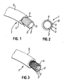
- the tubing generally designated 1 has a first P.V.C. (preferably black P.V.C.) tube 2 having a series of longitudinally oriented ridges 3.
- the tapered ridges 3 define valleys, each of which contains ( Figure 1) or is bridged by ( Figure 3) a reinforced polyamide yarn 4.
- Extruded over the first tube 2 and the reinforcing polyamide yarns is a second P.V.C. tube 5 having a smooth dimpled outer surface.
- the inner tubes 2 shown in Figures 1 and 2 have a varying number of ridges 3, dependent upon the diameter of the substrate, on the outer surface thereof. Normally, when longitudinal ridges are used as the formations on the inner tube, the ridges are conveniently equally spaced around the circumference of the outer surface thereof.
- each valley defined by the ridges 3 contains a reinforcing yarn, it will be appreciated that reinforcing yarn may be present in only some of the valleys if lesser strength is required.
- the present invention provides plastics tubing having many substantial advantages both as to its formation and to its qualities and characteristics when formed than hitherto known thermo-plastic tubing.
Landscapes
- Engineering & Computer Science (AREA)
- Mechanical Engineering (AREA)
- General Engineering & Computer Science (AREA)
- Extrusion Moulding Of Plastics Or The Like (AREA)
- Meat, Egg Or Seafood Products (AREA)
- Laminated Bodies (AREA)
Applications Claiming Priority (2)
| Application Number | Priority Date | Filing Date | Title |
|---|---|---|---|
| GB8009780 | 1980-03-22 | ||
| GB8009780 | 1980-03-22 |
Publications (3)
| Publication Number | Publication Date |
|---|---|
| EP0036674A2 true EP0036674A2 (fr) | 1981-09-30 |
| EP0036674A3 EP0036674A3 (en) | 1982-06-30 |
| EP0036674B1 EP0036674B1 (fr) | 1986-06-04 |
Family
ID=10512318
Family Applications (1)
| Application Number | Title | Priority Date | Filing Date |
|---|---|---|---|
| EP81200111A Expired EP0036674B1 (fr) | 1980-03-22 | 1981-01-30 | Méthode de fabrication à tuyaux en matière plastique |
Country Status (5)
| Country | Link |
|---|---|
| EP (1) | EP0036674B1 (fr) |
| DE (1) | DE3174751D1 (fr) |
| DK (1) | DK88181A (fr) |
| NO (1) | NO810097L (fr) |
| ZA (1) | ZA81247B (fr) |
Cited By (3)
| Publication number | Priority date | Publication date | Assignee | Title |
|---|---|---|---|---|
| EP0102422A1 (fr) * | 1981-08-31 | 1984-03-14 | David S. Sheridan | Fabrication de tubes médico-chirurgicaux renforcés |
| EP0445689A1 (fr) * | 1990-03-07 | 1991-09-11 | FILOTEX S.A. dite | Dispositif de renfort résistant à la traction pour une canalisation souple |
| EP2236888A3 (fr) * | 2009-04-02 | 2012-11-07 | Veritas Ag | Tuyau d'alimentation de milieux sur lesquels une pression est appliquée |
Families Citing this family (1)
| Publication number | Priority date | Publication date | Assignee | Title |
|---|---|---|---|---|
| US4201137A (en) * | 1978-04-03 | 1980-05-06 | American Zephyr Corporation | Sled and slide construction |
Family Cites Families (4)
| Publication number | Priority date | Publication date | Assignee | Title |
|---|---|---|---|---|
| GB1441573A (en) * | 1972-08-24 | 1976-07-07 | Alenco Hilyn Ltd | Flexible thermoplastic hose covers for roadway and like co |
| US3814138A (en) * | 1972-10-18 | 1974-06-04 | Weatherhead Co | Hose construction |
| US3860040A (en) * | 1973-03-07 | 1975-01-14 | Parker Hannifin Corp | Hose construction |
| US3866632A (en) * | 1973-07-02 | 1975-02-18 | Gates Rubber Co | Reinforced hose and method |
-
1981
- 1981-01-13 NO NO810097A patent/NO810097L/no unknown
- 1981-01-14 ZA ZA00810247A patent/ZA81247B/xx unknown
- 1981-01-30 EP EP81200111A patent/EP0036674B1/fr not_active Expired
- 1981-01-30 DE DE8181200111T patent/DE3174751D1/de not_active Expired
- 1981-02-27 DK DK88181A patent/DK88181A/da not_active Application Discontinuation
Cited By (4)
| Publication number | Priority date | Publication date | Assignee | Title |
|---|---|---|---|---|
| EP0102422A1 (fr) * | 1981-08-31 | 1984-03-14 | David S. Sheridan | Fabrication de tubes médico-chirurgicaux renforcés |
| EP0445689A1 (fr) * | 1990-03-07 | 1991-09-11 | FILOTEX S.A. dite | Dispositif de renfort résistant à la traction pour une canalisation souple |
| FR2659414A1 (fr) * | 1990-03-07 | 1991-09-13 | Filotex Sa | Dispositif de renfort resistant a la traction pour une canalisation souple. |
| EP2236888A3 (fr) * | 2009-04-02 | 2012-11-07 | Veritas Ag | Tuyau d'alimentation de milieux sur lesquels une pression est appliquée |
Also Published As
| Publication number | Publication date |
|---|---|
| DK88181A (da) | 1981-09-23 |
| EP0036674B1 (fr) | 1986-06-04 |
| DE3174751D1 (en) | 1986-07-10 |
| NO810097L (no) | 1981-09-23 |
| ZA81247B (en) | 1982-03-31 |
| EP0036674A3 (en) | 1982-06-30 |
Similar Documents
| Publication | Publication Date | Title |
|---|---|---|
| US3604461A (en) | Composite tubing | |
| US4306591A (en) | Hose with improved resistance to deformation, and method | |
| US2810424A (en) | Method and apparatus for making reinforced plastic tubing | |
| US4304266A (en) | Smooth bore flexible hose | |
| US4261390A (en) | Hose construction | |
| US4276908A (en) | Bonded thermoplastic hose | |
| US5901755A (en) | Flexible hose construction and method of making the same | |
| US4488577A (en) | Fire resistant hose | |
| US2969812A (en) | Pipe structure | |
| CA1089781A (fr) | Conduit flexible renforce avec chemisage moule integre et machine et methode de fabrication de ces conduits | |
| US4273160A (en) | High pressure hose | |
| US3866633A (en) | Hose structure | |
| US5690146A (en) | Hose and method for wear detection | |
| US5046531A (en) | Synthetic resin pipe for underground use | |
| CA2066257C (fr) | Tuyau souple et methode de fabrication | |
| US4813457A (en) | Flanged pipe part made of fiber-reinforced thermosetting synthetic resin with protective layer preventing crack formation in an angular intersection | |
| US3913624A (en) | Flexible reinforcing structures | |
| US3860040A (en) | Hose construction | |
| US3169552A (en) | Hose | |
| US4302266A (en) | Method for making high pressure hose | |
| US3011525A (en) | High pressure flexible hose | |
| US3755032A (en) | Method of making a high pressure hose of a single layer of untwisted textile reinforced rubber | |
| JPS60157580A (ja) | 補強ホ−スとその製造方法 | |
| JPH06169868A (ja) | 補強糸入りホースとその製造方法 | |
| HU183712B (en) | Coupling muff fitting and method for producing same |
Legal Events
| Date | Code | Title | Description |
|---|---|---|---|
| PUAI | Public reference made under article 153(3) epc to a published international application that has entered the european phase |
Free format text: ORIGINAL CODE: 0009012 |
|
| AK | Designated contracting states |
Designated state(s): DE FR GB IT NL SE |
|
| 17P | Request for examination filed |
Effective date: 19811009 |
|
| PUAL | Search report despatched |
Free format text: ORIGINAL CODE: 0009013 |
|
| AK | Designated contracting states |
Designated state(s): DE FR GB IT NL SE |
|
| ITF | It: translation for a ep patent filed | ||
| GRAA | (expected) grant |
Free format text: ORIGINAL CODE: 0009210 |
|
| AK | Designated contracting states |
Kind code of ref document: B1 Designated state(s): DE FR GB IT NL SE |
|
| REF | Corresponds to: |
Ref document number: 3174751 Country of ref document: DE Date of ref document: 19860710 |
|
| ET | Fr: translation filed | ||
| PLBI | Opposition filed |
Free format text: ORIGINAL CODE: 0009260 |
|
| 26 | Opposition filed |
Opponent name: SOLVAY & CIE, S.A. Effective date: 19861006 |
|
| NLR1 | Nl: opposition has been filed with the epo |
Opponent name: SOLVAY & CIE, S.A. |
|
| PLAB | Opposition data, opponent's data or that of the opponent's representative modified |
Free format text: ORIGINAL CODE: 0009299OPPO |
|
| PLAB | Opposition data, opponent's data or that of the opponent's representative modified |
Free format text: ORIGINAL CODE: 0009299OPPO |
|
| R26 | Opposition filed (corrected) |
Opponent name: SOLVAY & CIE, S.A., BRUXELLES Effective date: 19861006 |
|
| R26 | Opposition filed (corrected) |
Opponent name: SOLVAY & CIE, S.A., BRUXELLES Effective date: 19861006 |
|
| PLAB | Opposition data, opponent's data or that of the opponent's representative modified |
Free format text: ORIGINAL CODE: 0009299OPPO |
|
| PLAB | Opposition data, opponent's data or that of the opponent's representative modified |
Free format text: ORIGINAL CODE: 0009299OPPO |
|
| R26 | Opposition filed (corrected) |
Opponent name: SOLVAY & CIE, S.A., BRUXELLES Effective date: 19880811 |
|
| R26 | Opposition filed (corrected) |
Opponent name: SOLVAY & CIE, S.A., BRUXELLES Effective date: 19860610 |
|
| NLXE | Nl: other communications concerning ep-patents (part 3 heading xe) |
Free format text: IN PAT.BUL.02/87,PAGE 275:CORR.:860610 |
|
| ITTA | It: last paid annual fee | ||
| PLBN | Opposition rejected |
Free format text: ORIGINAL CODE: 0009273 |
|
| STAA | Information on the status of an ep patent application or granted ep patent |
Free format text: STATUS: OPPOSITION REJECTED |
|
| 27O | Opposition rejected |
Effective date: 19910702 |
|
| NLR2 | Nl: decision of opposition | ||
| EAL | Se: european patent in force in sweden |
Ref document number: 81200111.3 |
|
| PGFP | Annual fee paid to national office [announced via postgrant information from national office to epo] |
Ref country code: DE Payment date: 19991231 Year of fee payment: 20 |
|
| PGFP | Annual fee paid to national office [announced via postgrant information from national office to epo] |
Ref country code: SE Payment date: 20000107 Year of fee payment: 20 |
|
| PGFP | Annual fee paid to national office [announced via postgrant information from national office to epo] |
Ref country code: FR Payment date: 20000112 Year of fee payment: 20 |
|
| PGFP | Annual fee paid to national office [announced via postgrant information from national office to epo] |
Ref country code: GB Payment date: 20000126 Year of fee payment: 20 |
|
| PGFP | Annual fee paid to national office [announced via postgrant information from national office to epo] |
Ref country code: NL Payment date: 20000131 Year of fee payment: 20 |
|
| PG25 | Lapsed in a contracting state [announced via postgrant information from national office to epo] |
Ref country code: GB Free format text: LAPSE BECAUSE OF EXPIRATION OF PROTECTION Effective date: 20010129 |
|
| PG25 | Lapsed in a contracting state [announced via postgrant information from national office to epo] |
Ref country code: SE Free format text: THE PATENT HAS BEEN ANNULLED BY A DECISION OF A NATIONAL AUTHORITY Effective date: 20010130 Ref country code: NL Free format text: LAPSE BECAUSE OF EXPIRATION OF PROTECTION Effective date: 20010130 |
|
| REG | Reference to a national code |
Ref country code: GB Ref legal event code: PE20 Effective date: 20010129 |
|
| EUG | Se: european patent has lapsed |
Ref document number: 81200111.3 |
|
| NLV7 | Nl: ceased due to reaching the maximum lifetime of a patent |
Effective date: 20010130 |
|
| APAH | Appeal reference modified |
Free format text: ORIGINAL CODE: EPIDOSCREFNO |