EP0036717A1 - Milieu d'enregistrement magnétique - Google Patents
Milieu d'enregistrement magnétique Download PDFInfo
- Publication number
- EP0036717A1 EP0036717A1 EP81300905A EP81300905A EP0036717A1 EP 0036717 A1 EP0036717 A1 EP 0036717A1 EP 81300905 A EP81300905 A EP 81300905A EP 81300905 A EP81300905 A EP 81300905A EP 0036717 A1 EP0036717 A1 EP 0036717A1
- Authority
- EP
- European Patent Office
- Prior art keywords
- magnetic
- film
- recording medium
- vertical type
- magnetizable
- Prior art date
- Legal status (The legal status is an assumption and is not a legal conclusion. Google has not performed a legal analysis and makes no representation as to the accuracy of the status listed.)
- Withdrawn
Links
Images


Classifications
-
- G—PHYSICS
- G11—INFORMATION STORAGE
- G11B—INFORMATION STORAGE BASED ON RELATIVE MOVEMENT BETWEEN RECORD CARRIER AND TRANSDUCER
- G11B5/00—Recording by magnetisation or demagnetisation of a record carrier; Reproducing by magnetic means; Record carriers therefor
- G11B5/62—Record carriers characterised by the selection of the material
- G11B5/64—Record carriers characterised by the selection of the material comprising only the magnetic material without bonding agent
- G11B5/65—Record carriers characterised by the selection of the material comprising only the magnetic material without bonding agent characterised by its composition
- G11B5/656—Record carriers characterised by the selection of the material comprising only the magnetic material without bonding agent characterised by its composition containing Co
-
- Y—GENERAL TAGGING OF NEW TECHNOLOGICAL DEVELOPMENTS; GENERAL TAGGING OF CROSS-SECTIONAL TECHNOLOGIES SPANNING OVER SEVERAL SECTIONS OF THE IPC; TECHNICAL SUBJECTS COVERED BY FORMER USPC CROSS-REFERENCE ART COLLECTIONS [XRACs] AND DIGESTS
- Y10—TECHNICAL SUBJECTS COVERED BY FORMER USPC
- Y10S—TECHNICAL SUBJECTS COVERED BY FORMER USPC CROSS-REFERENCE ART COLLECTIONS [XRACs] AND DIGESTS
- Y10S428/00—Stock material or miscellaneous articles
- Y10S428/90—Magnetic feature
Definitions
- the present invention relates'to a magnetic recording medium particularly suitable for a magnetic record of vertical type having an improved short-wave recording characteristic by directing a residual magnetization in the direction of the normal to a medium.
- a magnetic recording medium has been used in which a magnetic film has an easily magnetizable axis parallel to the surface of said magnetic film.
- an antimagnetic field is strengthened for short-wave signals and a playing back output is remarkably decreased because a residual magnetization is directed in the direction parallel to the surface of said magnetic film.
- the requirement for a high density recording is remarkably strong in the recent magnetic recording field. This produces necessarily the requirement for short-wave recording signals more and more.
- the conventionally known magnetic film having said easily magnetizable axis parallel to the surface thereof can not satisfy the above mentioned requirement on account of the above mentioned reason.
- a method for recording and playing back (hereinafter referred to as a method for recording of vertical type), inwhich a residual magnetization is directed in the direction vertical to a medium, is proposed.
- This is a method for recording signals on a magnetic recording medium (hereinafter referred to as a recording medium of vertical type) provided with a thin magnetic film having an easily magnetizable axis in the direction vertical thereto (hereinafter referred to as a magnetizable film of vertical type) formed thereon by means of a magnetic head of vertical type consisting of a ferromagnetic thin film containing an exciting coil.
- a residual magnetization of a medium having signals recorded thereon is directed in the direction vertical to said medium and consequently an antimagnetic field is reduced and a playing back output is improved as the wave length of signals becomes shorter.
- the main components of the conventionally used magnetizable film of vertical type is Co and Cr.
- Said magnetizable film of vertical type has been manufactured by spattering.
- a spattered film containing Co.and Cr as its main components shows a compact-hexagonal crystalline construction within the limits of Cr content of about 30 or less'% by weight, being able to direct C-axis in the direction vertical to .the surface thereof, and being able to reduce a saturated magnetization until a crystalographically anisotropic magnetic field in the vertical direction becomes larger than an antimagnetic field.
- a magnetizable film of vertical type can be provided.
- An object of the present invention is to provide a magnetic recording medium of vertical type having an improved magnetic characteristic and corrosion resistance.
- FIG. 1 designates a magnetic recording medium consisting of a thin magnetic film 3 formed on a non-magnetic substrate 2 made of materials such as polyimide and the like. Said thin magnetic film 3 is constructed so as to have an easily magnetizable axis in the direction vertical thereto (in the direction of an arrow Shown in FIG. 1).
- 4 designates a head of vertical type consisting of a thin ferromagnetic film 6 containing exciting coils 5, said head 4 serving to record signals on said thin magnetic film 3 and play back recorded signals.
- a residual magnetization of a medium having signals recorded thereon is directed in the direction vertical to said medium and consequently an antimagnetic field is reduced and a playing back output is improved as the wave length of signals becomes shorter.
- Said thin magnetic film 3 has been manufactured by means of spattering. It is, however, difficult to manufacture a magnetizable film of vertical type at a low cost because the speed of forming a thin magnetic film is low in said spattering method.
- a magnetizable film of vertical type can be formed o at a speedy rate of several 100 to several 1,000 A/sec by adjusting.manufacturing conditions such as a temperature of a substrate and the like when forming a thin film.
- FIG. 2 is a graph showing.a relation between a content ratio of Co and Cr in a magnetic film formed by means of a vacuum deposition method and a coersive force vertical to said magnetic film. It is found from FIG. 2 that an improved magnetic characteristic can.be attained within the limits in which Cr is contained at the rate of 13 to 28% by weight based on a total of Co and Cr in said magnetic film. Although a relation between a coersive force vertical to said thin magnetic film and said content ratio of Co and Cr shows almost the same tendency as shown in"FIG. 2 when changing manufacturing conditions such as an atmosphere, a speed of forming a film, a temperature of a substrate and the like during vacuum deposition, its value and corrosion resistance are remarkably changed.
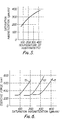
- FIG. 3 is a graph showing a relation between a Co content at % by weight of Co-Cr magnetizable film of vertical type obtained by a vacuum-deposition method and a saturated magnetization.
- the different values of a saturated magnetization for the same Cr content at % by weight are due to different conditions such as an atmosphere, a speed of forming a thin film, a temperature of a substrate and the like during vacuum deposition.
- a broken line 10 in FIG. 3 shows a relation between a Cr content of Co-Cr bulk and a saturated magnetization.
- FIG. 3 is a graph showing a relation between a Co content at % by weight of Co-Cr magnetizable film of vertical type obtained by a vacuum-deposition method and a saturated magnetization.
- FIG. 4 is a graph showing a relation between a pressure of Ar and a saturated magnetization for a magnetizable film of vertical type obtained by using Ar gas with a variety of pressures when vacuum deposition. But the Cr content of said thin film is held constant (20% by weight). Furthermore FIG 5 is a graph showing a relation between a saturated magnetization and a temperature of a substrate for Co-Cr magnetizable film of vertical type manufactured by vacuum deposition at a variety of temperature of a substrate. Also in this case the Cr content of said thin film is held constant (20% by weight). It is indicated from FIG. 4 that a saturated magnetization of said magnetizable film of vertical type is reduced as a pressure of Ar gas is increased in spite of the constant composition thereof while it is indicated from FIG. 5 that a saturated magnetization of said magnetizable film of vertical type is increased as a temperature of a substrate is lifted in spite of the constant composition thereof.
- FIG. 6 is a graph showing a relation between a saturated magnetization and a coersive force vertical to a surface of said film for a Co-Cr magnetizable film of vertical type obtained by a vacuum deposition method at a variety of manufacturing conditions.
- the curve 11, 12 and 13 shows the case in which the Cr content of said thin film is 18, 20 and 22% by weight, respectively.
- a coersive force is"hastily increased as the Cr content is increased, that is to say a saturated magnetization of said thin film is about 290 gausses or more, about 200 gausses or more and about 90 gausses or more for the Cr content of 18, 20 and 22% by weight, respectively.
- a saturated magnetization of 290, 200 and 90 gausses is equal to a saturated magnetization of the Co-Cr bulk containing Cr at the rate of 18, 20 and 22% by weight, respectively. Therefore, a magnetizable film showing a high coersive force can be obtained by increasing a saturated magnetization thereof larger than that of the Co-Cr bulk having the same composition.
- FIG. 7 is a graph showing a relation between a saturated magnetization and corrosion resistance for a Co-Cr magnetizable film of vertical type obtained by a vacuum deposition method at a variety of manufacturing conditions. But a corrosion resistance of said thin film is expressed by the ratio of a saturated magnetization thereof ater keeping thereof 2 months in an atmosphere having a temperature of 60°C and a humidity of 90% to that immediately after vacuum deposition. This value is left just as 1 if said thin film is not subjected to corrosion while this value is reduced as corrosion resistance is lowered.
- the curve 14, 15 and 16 shows the case in which the Cr content of said film is 18, 20 and 22% by weight, respectively.
- a saturated magnetization is about 290, 200 and 90 or more gausses for the Cr content of 18, 20 and 22% by weight, respectively and the value of the longitudinal axis is remarkably near to 1. It can be found from the above described that said thin film is hardly subjected to corrosion. Therefore also an improved corrosion resistance can be given to said Co-Cr magnetizable thin film by adjusting the Cr content thereof in the limits of 13 to 28% by weight and increasing a saturated magnetization thereof larger than that of the bulk having the same composition.
- Packing coefficient x is expressed by the quotient obtained by dividing a density of said magnetizable film (g/cm 3 ) by that of a single crystal (g/cm 3 ) having the same composition as said film.
- FIG. 8 is a graph showing a relation between a rate of vacuum deposition of a Co-Cr magnetizable film of vertical type and packing coefficient. But a temperature of a substrate and a degree of vacuum is 30°C and 4 x 10 -5 Torr, respectively. A Co-Cr ingot is heated by means of electron beams to evaporize. Packing coefficient becomes larger as a rate of vacuum deposition is increased.
- FIG. 9 is a graph showing a relation between a temperature of a substrate during vacuum deposition and packing coefficient for a Co-Cr magnetizable" film of vertical type obtained by means of a vacuum deposition method. But a degree of vacuum and a rate of vacuum deposition during vacuum deposition is 4 x 10 -5 Torr and 1,000 A/sec, respectively. A Co-Cr ingot was likewise heated by means of electron beams to evaporize. Packing coefficient is reduced as a temperature of a substrate is increased.
- FIG. 10 is a graph showing a relation between packing coefficient and a coersive force vertical to a surface of a Co-Cr magnetizable film of vertical type obtained by means of a vacuum deposition method at a variety of manufacturing conditions.
- a magnetizable film of vertical type having an improved short-wave recording characteristic can be obtained at packing coefficient of 0.95 or less which has a coersive force of 600 Oe or more while a coersive force of said film is remarkably reduced at packing.coefficient of 0.95 or more and as a result an electromagnetic conversion characteristic is.deteriorated so that said film is not suitable to a recording medium of vertical type.
- a magnetic thin film of this type can be provided for example by arranging two vacuum deposition sources, one of which is for depositing Cr and other is for depositing Co, parallel to the running direction of a non-magnetic substrate, arranging the former ahead of the running direction of said non-magnetic substrate while the latter is arranged in the rear of the running direction of said non-magnetic substrate.
- a magnetic thin film, in which the composition is changed along the thickness thereof, will be described below.
- a magnetic layer having the above described construction shows corrosion resistance of the same degree as that of the o superficial region of several 100 A thick.
- a magnetic layer of this type shows corrosion resistance of the same degree as that of the superficial layer thereof on the whole if an improved corrosion resistance is shown in the superficial o . layer of several 100 A thick even though a somewhat deteriorated corrosion resistance is shown in the deeper region.
- a magnetic layer of the above described construction shows almost the same recording and playing back efficiency as -.that of a magnetic layer having the same saturated magnetization as an average value of that for said magnetic layer of the above described construction. As shown for example by the curve 11 in FIG.
- Co-Cr magnetizable film of vertical type in which the content of Cr is 11% by weight in the boundary layer between said non-magnetic substrate and said magnetic layer, the content of Cr being increased toward the surface thereof, and the content of Cr being 18% by weight in the superficial layer thereof, said Co-Cr magnetizable film of vertical type can be sufficiently utilized as a magnetic recording medium in the natural circumstances (not oxidized in the usual operation) and shows a recording and playing back efficiency of the same degree as that of a Co-Cr magnetizable film of vertical type containing Cr at the rate of 14% by weight all over thereof (it goes without saying that the latter magnetizable film is somewhat inferior to the former one in corrosion resistance).
- the main point of the present invention is in that a thin film, in which the content of Cr is 13 to 28% by weight based on a total of Co and Cr, a saturated magnetization being larger than that of the bulk having the same composition, packing coefficient being in the limits of 0.75 to 0.95, and improved magnetic characteristics and corrosion resistance being given by the means such as increasing the content of Cr toward the surface thereof and the like, is used as a magnetic thin film for a magnetic recording medium.
- the magnetic recording medium according to the present invention will do much for a satisfaction of the requirement for a high-density record in the field of magnetic record and thus it is of industrial value.
Landscapes
- Magnetic Record Carriers (AREA)
- Manufacturing Of Magnetic Record Carriers (AREA)
Applications Claiming Priority (8)
| Application Number | Priority Date | Filing Date | Title |
|---|---|---|---|
| JP29622/80 | 1980-03-07 | ||
| JP2962280A JPS56127929A (en) | 1980-03-07 | 1980-03-07 | Magnetic recording medium |
| JP3061580A JPS56127930A (en) | 1980-03-10 | 1980-03-10 | Magnetic recording medium |
| JP30615/80 | 1980-03-10 | ||
| JP145166/80 | 1980-10-16 | ||
| JP55145166A JPS5771515A (en) | 1980-10-16 | 1980-10-16 | Magnetic recording medium |
| JP55159290A JPS5782227A (en) | 1980-11-11 | 1980-11-11 | Magnetic recording medium |
| JP159290/80 | 1980-11-11 |
Publications (1)
| Publication Number | Publication Date |
|---|---|
| EP0036717A1 true EP0036717A1 (fr) | 1981-09-30 |
Family
ID=27459097
Family Applications (1)
| Application Number | Title | Priority Date | Filing Date |
|---|---|---|---|
| EP81300905A Withdrawn EP0036717A1 (fr) | 1980-03-07 | 1981-03-04 | Milieu d'enregistrement magnétique |
Country Status (2)
| Country | Link |
|---|---|
| US (1) | US4429016A (fr) |
| EP (1) | EP0036717A1 (fr) |
Cited By (2)
| Publication number | Priority date | Publication date | Assignee | Title |
|---|---|---|---|---|
| FR2529366A1 (fr) * | 1982-06-28 | 1983-12-30 | Philips Nv | Milieu d'enregistrement magnetique |
| EP0089609A3 (en) * | 1982-03-16 | 1986-01-29 | Matsushita Electric Industrial Co., Ltd. | Magnetic recording medium and method of manufacturing a magnetic recording medium |
Families Citing this family (8)
| Publication number | Priority date | Publication date | Assignee | Title |
|---|---|---|---|---|
| JPS5961105A (ja) * | 1982-09-30 | 1984-04-07 | Fuji Photo Film Co Ltd | 磁気記録媒体 |
| US4599280A (en) * | 1983-04-25 | 1986-07-08 | Tdk Corporation | Magnetic recording medium |
| US4745005A (en) * | 1983-05-24 | 1988-05-17 | Matsushita Electric Industrial Co., Ltd. | Magnetic recording medium and method for making the same |
| US4587176A (en) * | 1985-01-14 | 1986-05-06 | E. I. Du Pont De Nemours And Company | Layered coherent structures for magnetic recording |
| DE3644823A1 (de) * | 1986-12-31 | 1988-07-14 | Basf Ag | Magnetische aufzeichnungstraeger |
| DE3831484A1 (de) * | 1988-09-16 | 1990-03-29 | Basf Ag | Verfahren zur herstellung von magnetischen aufzeichnungstraegern fuer die vertikalaufzeichnung |
| US5091253A (en) * | 1990-05-18 | 1992-02-25 | Allied-Signal Inc. | Magnetic cores utilizing metallic glass ribbons and mica paper interlaminar insulation |
| JPH04102223A (ja) * | 1990-08-20 | 1992-04-03 | Hitachi Ltd | 磁気記録媒体及びその製造方法並びに磁気記録装置 |
Citations (3)
| Publication number | Priority date | Publication date | Assignee | Title |
|---|---|---|---|---|
| FR1511664A (fr) * | 1966-12-23 | 1968-02-02 | Commissariat Energie Atomique | Couches minces à fort champ coercitif |
| GB2006508A (en) * | 1977-09-30 | 1979-05-02 | Iwasaki S | Magtenic recording media |
| EP0015692A1 (fr) * | 1979-02-23 | 1980-09-17 | Sekisui Kagaku Kogyo Kabushiki Kaisha | Procédé pour la fabrication d'un milieu d'enregistrement magnétique |
Family Cites Families (2)
| Publication number | Priority date | Publication date | Assignee | Title |
|---|---|---|---|---|
| GB1297936A (fr) | 1969-02-22 | 1972-11-29 | ||
| US4277809A (en) | 1979-09-26 | 1981-07-07 | Memorex Corporation | Apparatus for recording magnetic impulses perpendicular to the surface of a recording medium |
-
1981
- 1981-03-04 US US06/240,368 patent/US4429016A/en not_active Expired - Lifetime
- 1981-03-04 EP EP81300905A patent/EP0036717A1/fr not_active Withdrawn
Patent Citations (4)
| Publication number | Priority date | Publication date | Assignee | Title |
|---|---|---|---|---|
| FR1511664A (fr) * | 1966-12-23 | 1968-02-02 | Commissariat Energie Atomique | Couches minces à fort champ coercitif |
| US3787237A (en) * | 1966-12-23 | 1974-01-22 | Commissariat Energie Atomique | Method of making a thin film having a high coercive field |
| GB2006508A (en) * | 1977-09-30 | 1979-05-02 | Iwasaki S | Magtenic recording media |
| EP0015692A1 (fr) * | 1979-02-23 | 1980-09-17 | Sekisui Kagaku Kogyo Kabushiki Kaisha | Procédé pour la fabrication d'un milieu d'enregistrement magnétique |
Non-Patent Citations (1)
| Title |
|---|
| IEEE Transactions on Magnetics, Vol. Mag-14, No. 5, September 1978 SHUN-ICHI IWASAKI et al.: "CO-Cr Recording Films with Perpendicular Magnetic Anisotropy" pages 849-851 * figure 1, page 849 * * |
Cited By (2)
| Publication number | Priority date | Publication date | Assignee | Title |
|---|---|---|---|---|
| EP0089609A3 (en) * | 1982-03-16 | 1986-01-29 | Matsushita Electric Industrial Co., Ltd. | Magnetic recording medium and method of manufacturing a magnetic recording medium |
| FR2529366A1 (fr) * | 1982-06-28 | 1983-12-30 | Philips Nv | Milieu d'enregistrement magnetique |
Also Published As
| Publication number | Publication date |
|---|---|
| US4429016A (en) | 1984-01-31 |
Similar Documents
| Publication | Publication Date | Title |
|---|---|---|
| EP0053811B1 (fr) | Matériaux d'enregistrement magnétique | |
| US4661418A (en) | Magnetic recording medium | |
| US4578728A (en) | Magnetic head | |
| US4664976A (en) | Magnetic recording medium comprising a protective carbon nitride layer on the surface thereof | |
| EP0099124B1 (fr) | Système d'enregistrement ou de reproduction magnétique | |
| KR910007774B1 (ko) | 자기 기록 매체 | |
| EP0036717A1 (fr) | Milieu d'enregistrement magnétique | |
| US4362767A (en) | Magnetic thin film and method of making it | |
| US5858548A (en) | Soft magnetic thin film, and magnetic head and magnetic recording device using the same | |
| US5478416A (en) | Magnetic alloy | |
| US4786553A (en) | Magnetic recording medium | |
| EP0234879A2 (fr) | Film mince ferromagnétique et tête magnétique utilisant celui-ci | |
| US5304258A (en) | Magnetic alloy consisting of a specified FeTaN Ag or FeTaNCu composition | |
| EP0168825A2 (fr) | Film mince comportant un alliage magnétique | |
| US5413868A (en) | Perpendicular magnetic recording medium comprising a magnetic thin film of cobalt, palladium, chromium and oxygen | |
| JPH0647722B2 (ja) | 磁気記録媒体の製造方法 | |
| US5013616A (en) | Magnetic recording medium of thin metal film type | |
| US5082750A (en) | Magnetic recording medium of thin metal film type | |
| JP2552546B2 (ja) | 金属薄膜型磁気記録媒体 | |
| JPS6153769B2 (fr) | ||
| JPH0612568B2 (ja) | 磁気記録媒体 | |
| JPS6313256B2 (fr) | ||
| US4619720A (en) | Magnetic amorphous alloys comprising Co, Fe, Zr, and Nb | |
| JPS59157828A (ja) | 磁気記録媒体 | |
| US20040166369A1 (en) | High saturation flux density soft magnetic film |
Legal Events
| Date | Code | Title | Description |
|---|---|---|---|
| PUAI | Public reference made under article 153(3) epc to a published international application that has entered the european phase |
Free format text: ORIGINAL CODE: 0009012 |
|
| AK | Designated contracting states |
Designated state(s): DE FR GB |
|
| 17P | Request for examination filed |
Effective date: 19811026 |
|
| STAA | Information on the status of an ep patent application or granted ep patent |
Free format text: STATUS: THE APPLICATION IS DEEMED TO BE WITHDRAWN |
|
| 18D | Application deemed to be withdrawn |
Effective date: 19841002 |
|
| RIN1 | Information on inventor provided before grant (corrected) |
Inventor name: SUGITA, RYUJI |