EP0036937B1 - Bogentransporttrommel in Rotationsdruckmaschinen - Google Patents
Bogentransporttrommel in Rotationsdruckmaschinen Download PDFInfo
- Publication number
- EP0036937B1 EP0036937B1 EP81101102A EP81101102A EP0036937B1 EP 0036937 B1 EP0036937 B1 EP 0036937B1 EP 81101102 A EP81101102 A EP 81101102A EP 81101102 A EP81101102 A EP 81101102A EP 0036937 B1 EP0036937 B1 EP 0036937B1
- Authority
- EP
- European Patent Office
- Prior art keywords
- per
- sheet transport
- warp
- transport drum
- tex
- Prior art date
- Legal status (The legal status is an assumption and is not a legal conclusion. Google has not performed a legal analysis and makes no representation as to the accuracy of the status listed.)
- Expired
Links
- 238000007639 printing Methods 0.000 title claims description 10
- 229920000742 Cotton Polymers 0.000 claims description 23
- 239000004744 fabric Substances 0.000 claims description 22
- 239000004753 textile Substances 0.000 claims description 16
- 239000000203 mixture Substances 0.000 claims description 2
- 235000020004 porter Nutrition 0.000 claims 7
- 229920000297 Rayon Polymers 0.000 claims 1
- 230000032258 transport Effects 0.000 description 18
- 239000000463 material Substances 0.000 description 15
- 239000011521 glass Substances 0.000 description 9
- 239000011324 bead Substances 0.000 description 8
- 239000011148 porous material Substances 0.000 description 5
- 238000006748 scratching Methods 0.000 description 4
- 230000002393 scratching effect Effects 0.000 description 4
- 239000000853 adhesive Substances 0.000 description 3
- 230000001070 adhesive effect Effects 0.000 description 3
- 239000002313 adhesive film Substances 0.000 description 3
- 238000004140 cleaning Methods 0.000 description 3
- 239000000835 fiber Substances 0.000 description 3
- 230000000694 effects Effects 0.000 description 2
- 238000004519 manufacturing process Methods 0.000 description 2
- 238000000034 method Methods 0.000 description 2
- 230000000717 retained effect Effects 0.000 description 2
- 239000004677 Nylon Substances 0.000 description 1
- 230000002411 adverse Effects 0.000 description 1
- 239000012876 carrier material Substances 0.000 description 1
- 238000001816 cooling Methods 0.000 description 1
- 230000007423 decrease Effects 0.000 description 1
- 239000003599 detergent Substances 0.000 description 1
- 230000006866 deterioration Effects 0.000 description 1
- 238000006073 displacement reaction Methods 0.000 description 1
- 230000003670 easy-to-clean Effects 0.000 description 1
- 238000010438 heat treatment Methods 0.000 description 1
- 230000007774 longterm Effects 0.000 description 1
- 229920001778 nylon Polymers 0.000 description 1
- 238000007645 offset printing Methods 0.000 description 1
- 229920000728 polyester Polymers 0.000 description 1
- 238000003825 pressing Methods 0.000 description 1
- 238000003860 storage Methods 0.000 description 1
Images


Classifications
-
- B—PERFORMING OPERATIONS; TRANSPORTING
- B41—PRINTING; LINING MACHINES; TYPEWRITERS; STAMPS
- B41F—PRINTING MACHINES OR PRESSES
- B41F22/00—Means preventing smudging of machine parts or printed articles
Definitions
- the invention relates to an elevator of a sheet transport drum in the form of a textile covering for preventing the freshly printed underside of the sheet from smearing during the transport of the sheet.
- a sheet laying drum known from DE-B 1 561 043 is double-walled and has a cover made of porous and air-permeable material. Air is blown into the cavity between the double wall. This emerges through the air-permeable cover and creates an air cushion between the outer surface of the sheet delivery drum and the freshly printed underside of the sheet to be transported. The air cushion prevents the printed image from smearing.
- the known sheet delivery drum has the disadvantage that it is expensive to manufacture. Large amounts of blown air are required to generate the air cushion. In addition to the cost of the facility itself, there is a high energy requirement. In addition, the indoor climate of the print shop is adversely affected. With the large amount of air required, there is also an undesirable supply of heat to the machine, which can lead to paper warping.
- the use of this known sheet delivery drum therefore often requires additional cooling and dampening devices for the blown air, which has a cost-increasing effect.
- an elevator for a sheet transport drum which is designed as a glass bead cloth.
- the glass beads are e.g. glued on a rubber blanket and form a closed, non-porous surface with the adhesive.
- the surface of this well-known elevator shows different ink delivery behavior. While the load-bearing glass bead domes willingly return the color they have accepted to the arch, the valleys made of adhesive or rubber solution tend to build up color. The result is that such glass bead cloths have to be washed frequently, the individual glass beads very easily detaching from their adhesive connection. In the long run, glass bead cloths do not show satisfactory results in terms of preventing smearing.
- the known glass bead cloths can only be used to a limited extent on sheet delivery drums, because when the chain gripper passes from the circular path of the chain wheel into the straight chain track, the transported sheet is forced to have a slightly different speed than the surface speed of the outer surface of the sheet delivery drum. The resulting displacement of the freshly printed underside of the sheet relative to the elevator, namely to the glass bead cloth, causes the printed image to be smeared.
- DE-B 1 471 728 shows a textile carrier with a smooth surface and fiber inclusions, for example made of nylon, which protrude radially from the carrier material and are arranged symmetrically.
- These supporting fibers are designed, for example, as loops or loops. They can be subjected to heat treatment in order to achieve greater rigidity.
- the object of the invention is to provide an elevator for a sheet transport drum which can be produced with little resources and is easy to clamp and which prevents smearing and scratching of the printed image even when the freshly printed underside of the sheet moves relative to the elevator of the sheet transport drum.
- the elevator should allow trouble-free printing of runs of at least 500,000 prints without a deterioration in the printed image being ascertainable.
- the elevator should be easy to clean on the sheet transport drum.
- Dry rubbing is usually sufficient to clean these cloth-like elevators. Color residues that adhere to the tips of the fabric parts protruding from the load-bearing elevator surface can be rubbed off effortlessly. At larger intervals, wet cleaning using the usual rollers and mold detergents is also possible. However, tests have shown that such a wet cleaning of the elevator according to the invention is not necessary under 1,000,000 prints.
- the effect according to the invention on two supporting processes.
- the freshly printed underside of the sheet first meets a multitude of resilient support points of the rough surface structure of the textile material, in contrast to the glass beaded cloths, in which the support tips are unyielding in this regard.
- the flexibility of the supporting points of the textile material inevitably creates an air cushion because the structure of the textile material makes it difficult for the air to escape in any lateral direction.
- the impression cylinder 1 of the last printing unit of a multicolour sheet-fed offset printing machine transfers the printed sheet 2 to the gripper bridge 3 of a chain delivery 4.
- a sheet delivery drum 5 provided on the sprocket shaft 6 closest to the impression cylinder 1 guides the sheet 2 during the transfer process its freshly printed sheet side.
- the gripper bridge 3 transports the transferred sheets 2 to the sheet delivery stack 7.
- the outer surface 8 of the sheet delivery drum 5 is spanned by an elevator 9, which consists of a textile material with a rough surface structure that is compressible due to the presence of air pockets. It is an elevator made of a brushed, twill cotton (brushed denim material).
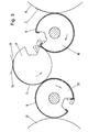
- FIG. 3 illustrates the mode of operation of an elevator according to the invention.
- the textile-like elevator 9 is compressed slightly due to the tension in the sheet 2. This is caused, among other things, by the fact that the sheet sticks to the rubber cylinder of the last printing unit, not shown, and has to be removed from its surface with the application of a certain force.
- Firmly nestling the sheet 2 gripped by the gripper bridges 3 onto the elevator 9 does two things. First of all, the freshly printed underside of the arch hugs the resilient supporting parts of the rough surface structure of the elevator material. Due to the tension in the arch mentioned above, these resilient supporting parts of the surface structure of the elevator 9 are pressed in.
- the fabric-like elevator 9 can be attached to the side walls 10 of the channel 11 of the sheet delivery drum 5 in a simple manner by means of Velcro fasteners 12.
- Velcro fasteners 12 consist on the one hand of an adhesive film provided with hooks and on the other hand of an adhesive film equipped with eyelets.
- One of these adhesive films is attached to the material elevator, the other to the wall 10 of the drum channel 11.
- the elevator 9 is stretched tightly by pressing one of the Velcro fasteners onto the other.
- the Velcro fastener thus enables the elevator 9 to be clamped and removed in a simple manner by hand. i.e. without the use of tools.
- the attachment of the ends of the elevator 9 by means of Velcro fasteners can also be carried out on other parts of the wall of the sheet laying drum 5 than just on the side walls 10 of the channel 11. Likewise, there is the possibility of providing a Velcro fastener part on the sheet laying drum 5, on which the textile-like elevator 9 directly is liable.
- the use of the elevator 9 according to the invention is not limited to the sheet delivery drum. Rather, such elevators 9, as shown in FIG. 5, can also be used in sheet transfer drums.
- a storage drum 15 transfers the already printed sheet 2 to the sheet transfer drum 16. Since the latter has to transport the sheet 2 on its printed side, it is provided with a textile-like elevator 9 according to the invention.
- the impression cylinder 17 takes over the sheet 2 from the sheet transfer drum 16 and guides it through the printing gap 18, which is formed between the blanket cylinder 19 and the impression cylinder 17. After printing again, the sheet 2 is taken over by a further sheet transfer drum 20, in which the freshly printed sheet side also comes to rest on the outer surface of the drum. Therefore, it is also provided with an elevator 9 according to the invention.
- the sheet is fed to the Spei chertrommel 21 passed on. Since this transports the sheet on the non-printed sheet side, it does not require an elevator 9 according to the invention, unless it is a perfecting machine. Because of the smudge-free transport of the sheets, their low manufacturing costs and their simple clamping and cleaning options, textile-type lifts according to the invention can be used with great advantage on all sheet transport drums. A particular advantage is also that the elevator can start right near the start of printing, which is not achievable in all known embodiments of sheet transport drums.
- the textile material which so far has retained the non-color-smearing and print-protecting properties even with long runs as the most suitable drum winder, was determined as a twill fabric with the K 3 S weave, the warp thread count of 33.4 per cm and the weft thread count of 19 per cm.
- the yarn count in the warp is 47.4 tex and in the weft 48.1 tex. This corresponds to a converted thread number in the warp of 21.1 and in the weft of 20.8.
- the number of warp lifts per cm 2 is 158.7.
- the warp and weft threads are made of pure cotton.
- the weight per unit area of this textile material is 293 g per m 2 , with a bulk density of 0.314 g per cm 3 and a pore fraction of 79.6 percent by volume.
- Another textile that has shown very good results has a twill weave with the weave S, whose warp thread count is 50.4 per cm and its weft thread count is 22.7 per cm.
- the yarn count in the warp is 27.4 tex, which corresponds to a yarn number of 36.5 and in the weft to 43.1 tex, which corresponds to a converted yarn number of 23.2.
- the number of warp raises is 286 per cm 2.
- the warp and weft threads are made of pure cotton.
- the weight per unit area of this textile material is 261 g per m 2 , with a bulk density of 0.381 g / cm 3 and a pore fraction of 79.6 volume percent.
- Another very suitable material is a twill weave with the bond which, however, has a warp thread count of 32.5 per cm and a weft thread count of 19.4 per cm.
- the yarn count in the normal state is 47.3 tex corresponding to a yarn number of 21.1 in the warp and 64.1 tex in the weft, which corresponds to a yarn number of 15.6.
- the number of warp raises amounts to 157.6 per cm 2.
- the warp and weft threads are made of pure cotton.
- the weight per unit area of this textile material is 315 g / M 2 , with a bulk density of 0.422 g / cm 3 and a pore fraction of 72.6 percent by volume.
- the two textiles listed below are less suitable for solving the task and represent actual borderline cases, of which the first dealt with has a very rough profile and the second described has a very smooth working surface.
- the textile with the largest profile of all the fabric samples listed here is a twill fabric with the weave , which has a warp thread count of 24.7 and a weft thread count of 15.0 per cm.
- the yarn count in the warp is 94.8 tex, which corresponds to a converted yarn number of 10.5, and the weft 68.6 tex, which corresponds to a converted yarn number of 14.6.
- the number of warp raises amounts to 92.6, whereby the warp is made of pure cotton, but the weft is made of a mixture of polyester and cotton.
- the weight per unit area of this textile material is 368 g / m 2.
- the bulk density is 0.335 g / cm 3 and the pore fraction is 77.7 percent by volume.
- This very smooth, ie with a low profile, is a cross twill with the binding , which has a warp thread count of 25 and a weft thread count of 14.5 per cm.
- the yarn count in the warp is 87.7 tex corresponding to the converted yarn number of 11.4 and in the weft 75.2 tex, which corresponds to a converted yarn number of 13.3.
- the number of warp raises amounts to 90.6 per cm 2 , both warp and weft threads made of pure cotton.
- the weight per unit area of this textile fabric is 366 g / m 2 .
- the bulk density is 0.352 g / cm 3 and the pore fraction is 77.1 percent by volume.
Landscapes
- Treatment Of Fiber Materials (AREA)
- Feeding Of Articles By Means Other Than Belts Or Rollers (AREA)
- Yarns And Mechanical Finishing Of Yarns Or Ropes (AREA)
- Machines For Manufacturing Corrugated Board In Mechanical Paper-Making Processes (AREA)
- Rolls And Other Rotary Bodies (AREA)
- Supply, Installation And Extraction Of Printed Sheets Or Plates (AREA)
- Sheets, Magazines, And Separation Thereof (AREA)
Priority Applications (1)
| Application Number | Priority Date | Filing Date | Title |
|---|---|---|---|
| AT81101102T ATE7674T1 (de) | 1980-03-31 | 1981-02-17 | Bogentransporttrommel in rotationsdruckmaschinen. |
Applications Claiming Priority (4)
| Application Number | Priority Date | Filing Date | Title |
|---|---|---|---|
| US13544680A | 1980-03-31 | 1980-03-31 | |
| US135446 | 1980-03-31 | ||
| US21511780A | 1980-12-10 | 1980-12-10 | |
| US215117 | 1998-12-18 |
Publications (2)
| Publication Number | Publication Date |
|---|---|
| EP0036937A1 EP0036937A1 (de) | 1981-10-07 |
| EP0036937B1 true EP0036937B1 (de) | 1984-05-30 |
Family
ID=26833327
Family Applications (1)
| Application Number | Title | Priority Date | Filing Date |
|---|---|---|---|
| EP81101102A Expired EP0036937B1 (de) | 1980-03-31 | 1981-02-17 | Bogentransporttrommel in Rotationsdruckmaschinen |
Country Status (11)
| Country | Link |
|---|---|
| EP (1) | EP0036937B1 (da) |
| JP (1) | JPS56151565A (da) |
| AU (1) | AU538331B2 (da) |
| BE (1) | BE887975A (da) |
| BR (1) | BR8101843A (da) |
| CA (1) | CA1154304A (da) |
| DE (2) | DE3163807D1 (da) |
| DK (1) | DK40181A (da) |
| ES (1) | ES267117Y (da) |
| IT (1) | IT1135456B (da) |
| NO (1) | NO811087L (da) |
Families Citing this family (14)
| Publication number | Priority date | Publication date | Assignee | Title |
|---|---|---|---|---|
| US4402267A (en) * | 1981-03-11 | 1983-09-06 | Printing Research Corporation | Method and apparatus for handling printed sheet material |
| DE3347886A1 (de) * | 1983-08-06 | 1985-05-30 | Heidelberger Druckmaschinen Ag, 6900 Heidelberg | Abschmierfreie umfuehrtrommel fuer bogenrotationsdruckmaschinen |
| DE3328451A1 (de) | 1983-08-06 | 1985-02-21 | Heidelberger Druckmaschinen Ag, 6900 Heidelberg | Abschmierfreie umfuehrtrommel fuer bogentotationsdruckmaschinen |
| DE3507925A1 (de) * | 1985-03-06 | 1986-09-11 | M.A.N.- Roland Druckmaschinen AG, 6050 Offenbach | Bogentransporttrommel fuer rotationsdruckmaschinen |
| US4691632A (en) * | 1986-07-08 | 1987-09-08 | Demoore Howard W | Method and apparatus for attaching anti-smear net to printing press transfer cylinder |
| JPS6323035U (da) * | 1986-07-30 | 1988-02-16 | ||
| US5042384A (en) * | 1990-04-30 | 1991-08-27 | Howard W. DeMoore | Anti-marking method and apparatus for use with perfector cylinders of rotary sheet-fed printing presses |
| DE4204254C2 (de) * | 1992-02-13 | 1995-03-16 | Koenig & Bauer Ag | Einrichtung zum Längsfalzen mehrerer gleichbreiter Papierbahnen in einer Rollenrotationsdruckmaschine |
| US5415098A (en) * | 1994-01-18 | 1995-05-16 | Ward; Donald A. | Method and apparatus for handling sheet material using ridged netting |
| DE4436583A1 (de) * | 1994-10-13 | 1996-04-18 | Heidelberger Druckmasch Ag | Vorrichtung zur Qualitätskontrolle von bedrucktem Papier in einer Rotationsdruckmaschine |
| US5907998A (en) * | 1995-12-29 | 1999-06-01 | Howard W. Demoore | Anti-static, anti-smearing pre-stretched and pressed flat, precision-cut striped flexible coverings for transfer cylinders |
| US5979322A (en) * | 1996-05-07 | 1999-11-09 | Demoore; Howard Warren | Environmentally safe, ink repellent, anti-marking flexible jacket covering having alignment stripes, centering marks and pre-fabricated reinforcement strips for attachment onto transfer cylinders in a printing press |
| US5842412A (en) * | 1997-03-07 | 1998-12-01 | Bba Nonwovens Simpsonville, Inc. | Anti-marking covering for printing press transfer cylinder |
| DE19745763A1 (de) * | 1997-10-16 | 1999-04-22 | Heidelberger Druckmasch Ag | Transporttrommel in Rotationsdruckmaschinen |
Family Cites Families (5)
| Publication number | Priority date | Publication date | Assignee | Title |
|---|---|---|---|---|
| US3126826A (en) * | 1964-03-31 | Transfer cylinder for rotary multi-color printing presses | ||
| US1336995A (en) * | 1919-07-31 | 1920-04-13 | Allen B Beck | Device for preventing offset in printing-presses |
| US3308522A (en) * | 1962-12-14 | 1967-03-14 | Velcro Corp | Anti-offset roll |
| AT341550B (de) * | 1975-05-10 | 1978-02-10 | Heidelberger Druckmasch Ag | Bogenuberfuhrtrommel fur druckmaschinen |
| GB1505623A (en) * | 1975-07-11 | 1978-03-30 | Heidelberger Druckmasch Ag | Transfer drum and drum blanket for sheet-fed rotary printing presses |
-
1981
- 1981-01-29 DK DK40181A patent/DK40181A/da not_active Application Discontinuation
- 1981-02-13 IT IT19719/81A patent/IT1135456B/it active
- 1981-02-17 DE DE8181101102T patent/DE3163807D1/de not_active Expired
- 1981-02-17 DE DE3105683A patent/DE3105683C2/de not_active Expired
- 1981-02-17 EP EP81101102A patent/EP0036937B1/de not_active Expired
- 1981-02-20 CA CA000371341A patent/CA1154304A/en not_active Expired
- 1981-02-27 AU AU67937/81A patent/AU538331B2/en not_active Ceased
- 1981-03-16 BE BE0/204146A patent/BE887975A/fr not_active IP Right Cessation
- 1981-03-18 ES ES1981267117U patent/ES267117Y/es not_active Expired
- 1981-03-27 BR BR8101843A patent/BR8101843A/pt unknown
- 1981-03-30 NO NO811087A patent/NO811087L/no unknown
- 1981-03-31 JP JP4656481A patent/JPS56151565A/ja active Pending
Also Published As
| Publication number | Publication date |
|---|---|
| DE3105683C2 (de) | 1985-03-28 |
| EP0036937A1 (de) | 1981-10-07 |
| DE3105683A1 (de) | 1982-03-04 |
| ES267117Y (es) | 1983-08-16 |
| NO811087L (no) | 1981-11-30 |
| AU6793781A (en) | 1981-10-08 |
| ES267117U (es) | 1983-02-16 |
| JPS56151565A (en) | 1981-11-24 |
| AU538331B2 (en) | 1984-08-09 |
| DE3163807D1 (en) | 1984-07-05 |
| DK40181A (da) | 1981-10-01 |
| BR8101843A (pt) | 1981-10-06 |
| IT1135456B (it) | 1986-08-20 |
| CA1154304A (en) | 1983-09-27 |
| IT8119719A0 (it) | 1981-02-13 |
| BE887975A (fr) | 1981-07-16 |
Similar Documents
| Publication | Publication Date | Title |
|---|---|---|
| EP0189876B1 (de) | Flocktransferfolien-Zuschnitt | |
| DE69117642T2 (de) | Hochelongiertes Gewebe enthaltendes Drucktuch | |
| DE3105683C2 (de) | Textiler Aufzug für eine Bogenauslegetrommel | |
| EP2349722B1 (de) | Vorrichtung und verfahren zur reinigung von gummitüchern auf gummituchzylindern | |
| DE3841260A1 (de) | Vorrichtung und verfahren zur reinigung einer druckerpressendecke | |
| DE69627974T2 (de) | Flexibler, vorgestreckter, flachgepresster, präzisionsgeschnittener, nichtschmierender Überzug für eine Bogentransporttrommel mit Streifenmuster | |
| DE3422443A1 (de) | Aufzug fuer bogenfuehrende zylinder und trommeln in rotationsoffsetdruckmaschinen | |
| DE69325103T2 (de) | Druchtuch mit verbesserter dickenstabilität bei gebrauch | |
| DE19648494C2 (de) | Drucktuch für Offsetdruck | |
| DE69314987T2 (de) | Endlosband für den Gebrauch als Drucktuch | |
| DE1258873B (da) | ||
| EP0022459B1 (de) | Farbkasten für Offset- oder Hochdruckmaschinen | |
| DE2249195A1 (de) | Zusammengesetzte druckplatte zum anbringen auf dem plattenzylinder einer offsetdruckmaschine | |
| DE4111469C2 (de) | Überzug für eine Walze einer Anfeuchtvorrichtung einer Offsetdruckmaschine | |
| EP0424716B1 (de) | Tampondruckmaschine mit Tamponreinigungsvorrichtung und Verfahren zu dessen Betrieb | |
| DE69500899T2 (de) | Rotationsschablonendruckmaschine | |
| DE3419599A1 (de) | Ueberzug | |
| DE3326003C2 (de) | Überzugsgewebe für Feuchtwalzen für Offset-Maschinen | |
| DE3901174C2 (de) | Verfahren zum Bedrucken eines Druckbogens nach dem Bildtransportprinzip und eine Bildtransportdruckmaschine | |
| DD293548A5 (de) | Anordnung eines textilen aufzuges auf uebergabetrommeln von druckmaschinen | |
| DE68926788T2 (de) | Verdichtbare kautschukdecke für offsetdruck | |
| DE3015519A1 (de) | Bogenrotationsdruckmaschine mit mindestens einem druckwert | |
| DE29706932U1 (de) | Feuchtwerk für eine Offsetdruckmaschine | |
| DE10115876A1 (de) | Farbabweisende Beschichtung für ein einen Bedruckstoff kontaktierendes Element | |
| DE3901176C2 (de) | Druckmaschine |
Legal Events
| Date | Code | Title | Description |
|---|---|---|---|
| PUAI | Public reference made under article 153(3) epc to a published international application that has entered the european phase |
Free format text: ORIGINAL CODE: 0009012 |
|
| AK | Designated contracting states |
Designated state(s): AT CH DE FR GB IT LU NL SE |
|
| 17P | Request for examination filed |
Effective date: 19811114 |
|
| ITF | It: translation for a ep patent filed | ||
| GRAA | (expected) grant |
Free format text: ORIGINAL CODE: 0009210 |
|
| AK | Designated contracting states |
Designated state(s): AT CH DE FR GB IT LI LU NL SE |
|
| REF | Corresponds to: |
Ref document number: 7674 Country of ref document: AT Date of ref document: 19840615 Kind code of ref document: T |
|
| REF | Corresponds to: |
Ref document number: 3163807 Country of ref document: DE Date of ref document: 19840705 |
|
| ET | Fr: translation filed | ||
| PGFP | Annual fee paid to national office [announced via postgrant information from national office to epo] |
Ref country code: AT Payment date: 19841228 Year of fee payment: 5 |
|
| PG25 | Lapsed in a contracting state [announced via postgrant information from national office to epo] |
Ref country code: LU Free format text: LAPSE BECAUSE OF NON-PAYMENT OF DUE FEES Effective date: 19850228 |
|
| PGFP | Annual fee paid to national office [announced via postgrant information from national office to epo] |
Ref country code: NL Payment date: 19850228 Year of fee payment: 5 |
|
| PLBE | No opposition filed within time limit |
Free format text: ORIGINAL CODE: 0009261 |
|
| STAA | Information on the status of an ep patent application or granted ep patent |
Free format text: STATUS: NO OPPOSITION FILED WITHIN TIME LIMIT |
|
| 26N | No opposition filed | ||
| PG25 | Lapsed in a contracting state [announced via postgrant information from national office to epo] |
Ref country code: AT Effective date: 19860217 |
|
| PG25 | Lapsed in a contracting state [announced via postgrant information from national office to epo] |
Ref country code: LI Effective date: 19860228 Ref country code: CH Effective date: 19860228 |
|
| PG25 | Lapsed in a contracting state [announced via postgrant information from national office to epo] |
Ref country code: NL Effective date: 19860901 |
|
| NLV4 | Nl: lapsed or anulled due to non-payment of the annual fee | ||
| REG | Reference to a national code |
Ref country code: CH Ref legal event code: PL |
|
| PG25 | Lapsed in a contracting state [announced via postgrant information from national office to epo] |
Ref country code: SE Effective date: 19870218 |
|
| GBPC | Gb: european patent ceased through non-payment of renewal fee | ||
| PG25 | Lapsed in a contracting state [announced via postgrant information from national office to epo] |
Ref country code: FR Free format text: LAPSE BECAUSE OF NON-PAYMENT OF DUE FEES Effective date: 19871030 |
|
| PG25 | Lapsed in a contracting state [announced via postgrant information from national office to epo] |
Ref country code: DE Effective date: 19871201 |
|
| REG | Reference to a national code |
Ref country code: FR Ref legal event code: ST |
|
| PG25 | Lapsed in a contracting state [announced via postgrant information from national office to epo] |
Ref country code: GB Effective date: 19881118 |
|
| EUG | Se: european patent has lapsed |
Ref document number: 81101102.2 Effective date: 19880215 |