EP0036996A2 - Dispositif d'estimation à résistances pour capteur de température de radiateurs - Google Patents
Dispositif d'estimation à résistances pour capteur de température de radiateurs Download PDFInfo
- Publication number
- EP0036996A2 EP0036996A2 EP81101923A EP81101923A EP0036996A2 EP 0036996 A2 EP0036996 A2 EP 0036996A2 EP 81101923 A EP81101923 A EP 81101923A EP 81101923 A EP81101923 A EP 81101923A EP 0036996 A2 EP0036996 A2 EP 0036996A2
- Authority
- EP
- European Patent Office
- Prior art keywords
- resistors
- circuit board
- short
- resistor arrangement
- resistance values
- Prior art date
- Legal status (The legal status is an assumption and is not a legal conclusion. Google has not performed a legal analysis and makes no representation as to the accuracy of the status listed.)
- Withdrawn
Links
Images
Classifications
-
- H—ELECTRICITY
- H01—ELECTRIC ELEMENTS
- H01C—RESISTORS
- H01C17/00—Apparatus or processes specially adapted for manufacturing resistors
- H01C17/22—Apparatus or processes specially adapted for manufacturing resistors adapted for trimming
- H01C17/23—Apparatus or processes specially adapted for manufacturing resistors adapted for trimming by opening or closing resistor geometric tracks of predetermined resistive values, e.g. snapistors
-
- G—PHYSICS
- G01—MEASURING; TESTING
- G01K—MEASURING TEMPERATURE; MEASURING QUANTITY OF HEAT; THERMALLY-SENSITIVE ELEMENTS NOT OTHERWISE PROVIDED FOR
- G01K17/00—Measuring quantity of heat
- G01K17/06—Measuring quantity of heat conveyed by flowing media, e.g. in heating systems e.g. the quantity of heat in a transporting medium, delivered to or consumed in an expenditure device
Definitions
- the invention relates to an evaluation resistor arrangement for adapting measuring and comparison sensors containing measuring circuits to the heating power of radiators, underfloor heating, air conditioning or similar devices, the heat output of which is measured.
- the radiators and a wall are each provided with a measuring and a comparison sensor.
- Measuring and comparison sensors form a system to which an evaluation resistor is assigned. With this evaluation resistor, the sensor system is adapted to the area of the respective radiator (DT-OS 27 34 406).
- the output of the radiators depends on the material and the surface available. Since the radiators are manufactured in graduated sizes, there are also stages for the heat output. Therefore, the use of evaluation resistors with their values adapted to the levels of the radiator output is sufficient for the adaptation.
- the object of the invention is to develop an evaluation resistor arrangement which can be used for a wide range of radiator outputs and which is quick and easy at the installation site of the radiator can be adjusted to the performance of the radiator without using a measuring device.
- resistors are connected in series on a carrier plate, the resistance values of which are adapted to predetermined levels of heating power, and that the resistors are each bridged by easily separable short-circuit lines, which are separated for those resistors whose resistance values are individually or together the Correspond to the heating output of the assigned radiator.
- this arrangement can cover all stages of a radiator program comprising a power of 200 to 6000 watts. Therefore, one type of evaluation resistor arrangement is sufficient for all individual cases. There is only a small adjustment error, which is due to the unequal jumps in performance between the different radiators. Since only one type is required, larger quantities can be manufactured inexpensively. In addition, storage and distribution are simplified.
- the short-circuit lines are arranged as printed conductor tracks on the carrier plate and some of them run on rectangular projections of the edges of the circuit board, the projections being easily broken off.
- the selected protrusions can be z. B. be broken off with flat-nose pliers.
- Another preferred embodiment consists in that the short-circuit lines are arranged as printed conductor tracks on the printed circuit board and with a part extending between the edge of the printed circuit board and bores arranged close to the edge over easily breakable plate sections.
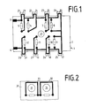
- An evaluation resistor arrangement 1 contains a printed circuit board 2 made of plastic with connections 3 and 4. Ohmic resistors 5, 6, 7, 8, 9, 10, 11 and 12 are connected in series on the printed circuit board 2. The connections between two resistors are made by unspecified printed conductor tracks. 1 shows the conductor track side of the printed circuit board 2. The resistors 5 to 12, the connecting wires of which are fastened in the pads of the conductor tracks, are located on the other side of the circuit board 2 and are therefore shown in broken lines.
- the resistors 5 to 12 are bridged by short-circuit lines 13, 14, 15, 16, 17, 18, 19 and 20, respectively. These short-circuit lines run in the form of printed conductor tracks each over rectangular projections 21, 22, 23, 24, 25, 26, 27 and 28 of the printed circuit board 2. When the projections 21 to 28 are broken off, the respective conductor track 13, 14, 15, 16, 17, 18, 19 and 20 interrupted. As a result, the associated resistor is inserted into the current path running between the connections 3 and 4.
- the resistors 5 to 12 each have values assigned to the heating powers 25, 50, 100, 200, 400, 800, 1600 and 3200 W.
- the arrangement is then adapted to a radiator with a power of 200 W by separating the projection 24.
- the arrangement is suitable for a heating power of, for. B. 480 ⁇ adjusted.
- the mismatch here is 20 W.
- the arrangement shown in Figure 1 has a maximum mismatch of 25 W, a value that in practice is a sufficiently accurate determination of the amount of heat consumed allowed. It must be taken into account here that the radiators are available with heat outputs from 200 W. However, radiators with higher outputs are mainly used.
- the circuit board 2 is preferably selected in its dimensions so that it can be used in a conventional flush or surface box. It has a hole 29 in the middle for inserting fasteners.
- the printed circuit board 30 shown in FIG. 2 has bores 31 instead of projections, which run close to the edge 32 of the board.
- Short-circuit lines 33 for the resistors on circuit board 30, which are not described in more detail, run between edge 32 and bores 31. They are separated by the removal of the material between bore 31 and edge 32.
- the evaluation resistor arrangement explained above is advantageously also used in underfloor heating or air conditioning systems. It can also be used to determine the cooling capacity of air conditioning systems. In addition, it is suitable in all cases for determining the heat consumption in which the heat consumption is to be determined by the heat consumer. For example, the heat transfer between partitions can be determined.
Landscapes
- Engineering & Computer Science (AREA)
- Chemical & Material Sciences (AREA)
- Combustion & Propulsion (AREA)
- Physics & Mathematics (AREA)
- General Physics & Mathematics (AREA)
- Manufacturing & Machinery (AREA)
- Microelectronics & Electronic Packaging (AREA)
- Investigating Or Analyzing Materials Using Thermal Means (AREA)
- Measuring Instrument Details And Bridges, And Automatic Balancing Devices (AREA)
Applications Claiming Priority (2)
| Application Number | Priority Date | Filing Date | Title |
|---|---|---|---|
| DE19803012436 DE3012436A1 (de) | 1980-03-31 | 1980-03-31 | Bewertungswiderstandsanordnung fuer heizkoerperfuehler |
| DE3012436 | 1980-03-31 |
Publications (2)
| Publication Number | Publication Date |
|---|---|
| EP0036996A2 true EP0036996A2 (fr) | 1981-10-07 |
| EP0036996A3 EP0036996A3 (fr) | 1982-09-08 |
Family
ID=6098862
Family Applications (1)
| Application Number | Title | Priority Date | Filing Date |
|---|---|---|---|
| EP81101923A Withdrawn EP0036996A3 (fr) | 1980-03-31 | 1981-03-16 | Dispositif d'estimation à résistances pour capteur de température de radiateurs |
Country Status (2)
| Country | Link |
|---|---|
| EP (1) | EP0036996A3 (fr) |
| DE (1) | DE3012436A1 (fr) |
Cited By (6)
| Publication number | Priority date | Publication date | Assignee | Title |
|---|---|---|---|---|
| EP0087112A1 (fr) * | 1982-02-19 | 1983-08-31 | Solitron Devices, Inc. | Chip à fonctions multiples |
| EP0099511A3 (fr) * | 1982-07-06 | 1985-05-29 | Kieninger & Obergfell Fabrik für technische Laufwerke und Apparate GmbH & Co. | Distributeur électrique de frais de chauffage |
| DE3447130A1 (de) * | 1984-12-22 | 1986-06-26 | Kieninger & Obergfell, Fabrik für technische Laufwerke und Apparate GmbH & Co, 7742 St Georgen | elektrischer heizkostenverteiler |
| EP0494680A3 (en) * | 1991-01-10 | 1992-10-07 | Fuji Photo Film Co., Ltd. | A photographic camera |
| DE10012842A1 (de) * | 2000-03-16 | 2001-09-20 | Siemens Building Tech Ag | Vorrichtung und Verfahren zur Programmierung von elektronischen Geräten |
| CN119964914A (zh) * | 2024-12-31 | 2025-05-09 | 广东福德电子有限公司 | 一种可调节带式电阻 |
Families Citing this family (2)
| Publication number | Priority date | Publication date | Assignee | Title |
|---|---|---|---|---|
| DE3203778A1 (de) * | 1982-02-04 | 1983-08-11 | Licentia Patent-Verwaltungs-Gmbh, 6000 Frankfurt | Bewertungswiderstandsanordnung fuer heizkoerperfuehler |
| DE102005032834B4 (de) * | 2005-07-12 | 2007-10-25 | Ista Shared Services Gmbh | Verfahren und Heizkostenverteiler zur Erfassung des Heizwärmeverbrauchs bei Heizkörpern |
Family Cites Families (2)
| Publication number | Priority date | Publication date | Assignee | Title |
|---|---|---|---|---|
| IT1026380B (it) * | 1974-04-10 | 1978-09-20 | Draloric Electronic | Elemento costruttivo elettrico per circuiti a film spesso o film sottile |
| NL7807191A (nl) * | 1977-07-29 | 1979-01-31 | Licentia Gmbh | Werkwijze en inrichting voor het elektrisch registre- ren van de warmte energie, afgegeven door in ruimten aangebrachte radiatorverwarmingslichamen. |
-
1980
- 1980-03-31 DE DE19803012436 patent/DE3012436A1/de not_active Withdrawn
-
1981
- 1981-03-16 EP EP81101923A patent/EP0036996A3/fr not_active Withdrawn
Cited By (6)
| Publication number | Priority date | Publication date | Assignee | Title |
|---|---|---|---|---|
| EP0087112A1 (fr) * | 1982-02-19 | 1983-08-31 | Solitron Devices, Inc. | Chip à fonctions multiples |
| EP0099511A3 (fr) * | 1982-07-06 | 1985-05-29 | Kieninger & Obergfell Fabrik für technische Laufwerke und Apparate GmbH & Co. | Distributeur électrique de frais de chauffage |
| DE3447130A1 (de) * | 1984-12-22 | 1986-06-26 | Kieninger & Obergfell, Fabrik für technische Laufwerke und Apparate GmbH & Co, 7742 St Georgen | elektrischer heizkostenverteiler |
| EP0494680A3 (en) * | 1991-01-10 | 1992-10-07 | Fuji Photo Film Co., Ltd. | A photographic camera |
| DE10012842A1 (de) * | 2000-03-16 | 2001-09-20 | Siemens Building Tech Ag | Vorrichtung und Verfahren zur Programmierung von elektronischen Geräten |
| CN119964914A (zh) * | 2024-12-31 | 2025-05-09 | 广东福德电子有限公司 | 一种可调节带式电阻 |
Also Published As
| Publication number | Publication date |
|---|---|
| DE3012436A1 (de) | 1981-10-15 |
| EP0036996A3 (fr) | 1982-09-08 |
Similar Documents
| Publication | Publication Date | Title |
|---|---|---|
| DE3802593C2 (fr) | ||
| DE69101386T2 (de) | Strommess-Schaltung in einem MOS-Leistungstransistor. | |
| DE3134166C2 (fr) | ||
| CH640938A5 (de) | Elektronisches geraet nach dem baukastenprinzip zur verarbeitung einer mehrzahl von simultanen messsignalen, insbesondere zur verwendung bei der ueberpruefung von geometrischen abmessungen. | |
| DE3012436A1 (de) | Bewertungswiderstandsanordnung fuer heizkoerperfuehler | |
| DE4006186C2 (de) | Verfahren zur Regelung der Drehzahl einer von einem drehzahlgeregelten Elektromotor angetriebenen Pumpe | |
| EP0064218A2 (fr) | Dispositif de mesure de grandeur physiques | |
| DE3511144C2 (fr) | ||
| DE3722000A1 (de) | Vorrichtung zur messung der temperatur eines mediums, insbesondere zur messung der innenraumtemperatur in einem kraftfahrzeug | |
| DE69216937T2 (de) | Detektionsvorrichtung zur Auswertung thermischer Klimabedingungen eines Milieus, zum Beispiel eines Kraftfahrzeuginnenraums | |
| DE2645743C2 (de) | Flüssigkeitsstandsmeßeinrichtung | |
| EP0202401A2 (fr) | Elément chauffant | |
| DE102021130006B3 (de) | Verfahren zum bestimmen eines einschaltwiderstands eines feldeffekt-transistors, modul zur stromerfassung mit einem feldeffekt-transistor und elektronische sicherung mit dem modul | |
| DE71366T1 (de) | Lampen-betriebsschaltung. | |
| DE4113258A1 (de) | Leistungssteuerschaltung mit kurzschlussschutzschaltung | |
| DE3519010C1 (de) | Gerätehalter für ein geregeltes Lötgerät mit Absenkung der Ablagetemperatur | |
| DE2539117C3 (de) | Verfahren und Einrichtung zur Aufladung einer elektrischen Speicherheizung | |
| DE69006162T2 (de) | Anordnung für elektronische schaltung. | |
| DE3123336A1 (de) | Waermezaehler | |
| DE3203778A1 (de) | Bewertungswiderstandsanordnung fuer heizkoerperfuehler | |
| DE3306460A1 (de) | Elektrisches feuchtemessgeraet | |
| DE10322012A1 (de) | Durchflusssensor mit verbessertem Betriebsverhalten | |
| DE19836134B4 (de) | Einrichtung zum Sammeln der Kenndaten und zur verbraucherspezifischen Optimierung von Solarzellen | |
| DE1640295C3 (de) | Schaltungsanordnung zur Einstellung einer mehrstellig dekadisch abgestuften Spannung | |
| DE2711774A1 (de) | Messgeraet zum automatischen messen des widerstandes und der erwaermung von widerstandsbehafteten elektrischen bauelementen |
Legal Events
| Date | Code | Title | Description |
|---|---|---|---|
| PUAI | Public reference made under article 153(3) epc to a published international application that has entered the european phase |
Free format text: ORIGINAL CODE: 0009012 |
|
| AK | Designated contracting states |
Designated state(s): AT BE CH FR GB IT NL |
|
| PUAL | Search report despatched |
Free format text: ORIGINAL CODE: 0009013 |
|
| RHK1 | Main classification (correction) |
Ipc: H01C 17/22 |
|
| AK | Designated contracting states |
Designated state(s): AT BE CH FR GB IT NL |
|
| STAA | Information on the status of an ep patent application or granted ep patent |
Free format text: STATUS: THE APPLICATION IS DEEMED TO BE WITHDRAWN |
|
| 18D | Application deemed to be withdrawn |
Effective date: 19830817 |
|
| RIN1 | Information on inventor provided before grant (corrected) |
Inventor name: OHL, REINHARD Inventor name: GOTTFRIED, GERD-ULRICH |