EP0037073A2 - Dispositif de centrage pour la réalisation d'un trou au centre de disques - Google Patents
Dispositif de centrage pour la réalisation d'un trou au centre de disques Download PDFInfo
- Publication number
- EP0037073A2 EP0037073A2 EP81102248A EP81102248A EP0037073A2 EP 0037073 A2 EP0037073 A2 EP 0037073A2 EP 81102248 A EP81102248 A EP 81102248A EP 81102248 A EP81102248 A EP 81102248A EP 0037073 A2 EP0037073 A2 EP 0037073A2
- Authority
- EP
- European Patent Office
- Prior art keywords
- plate
- measuring head
- information
- light beam
- center
- Prior art date
- Legal status (The legal status is an assumption and is not a legal conclusion. Google has not performed a legal analysis and makes no representation as to the accuracy of the status listed.)
- Granted
Links
- 238000004519 manufacturing process Methods 0.000 claims abstract description 4
- 230000005855 radiation Effects 0.000 claims description 5
- 238000004080 punching Methods 0.000 claims description 3
- 230000005540 biological transmission Effects 0.000 claims 1
- 230000007704 transition Effects 0.000 abstract description 2
- 238000006073 displacement reaction Methods 0.000 abstract 1
- 238000000034 method Methods 0.000 description 4
- 230000003287 optical effect Effects 0.000 description 4
- 230000007547 defect Effects 0.000 description 1
- 239000000428 dust Substances 0.000 description 1
- 238000011156 evaluation Methods 0.000 description 1
- 230000004807 localization Effects 0.000 description 1
- 238000005259 measurement Methods 0.000 description 1
Images
Classifications
-
- G—PHYSICS
- G11—INFORMATION STORAGE
- G11B—INFORMATION STORAGE BASED ON RELATIVE MOVEMENT BETWEEN RECORD CARRIER AND TRANSDUCER
- G11B23/00—Record carriers not specific to the method of recording or reproducing; Accessories, e.g. containers, specially adapted for co-operation with the recording or reproducing apparatus ; Intermediate mediums; Apparatus or processes specially adapted for their manufacture
- G11B23/0014—Record carriers not specific to the method of recording or reproducing; Accessories, e.g. containers, specially adapted for co-operation with the recording or reproducing apparatus ; Intermediate mediums; Apparatus or processes specially adapted for their manufacture record carriers not specifically of filamentary or web form
- G11B23/0021—Record carriers not specific to the method of recording or reproducing; Accessories, e.g. containers, specially adapted for co-operation with the recording or reproducing apparatus ; Intermediate mediums; Apparatus or processes specially adapted for their manufacture record carriers not specifically of filamentary or web form discs
-
- G—PHYSICS
- G01—MEASURING; TESTING
- G01B—MEASURING LENGTH, THICKNESS OR SIMILAR LINEAR DIMENSIONS; MEASURING ANGLES; MEASURING AREAS; MEASURING IRREGULARITIES OF SURFACES OR CONTOURS
- G01B11/00—Measuring arrangements characterised by the use of optical techniques
- G01B11/26—Measuring arrangements characterised by the use of optical techniques for measuring angles or tapers; for testing the alignment of axes
- G01B11/27—Measuring arrangements characterised by the use of optical techniques for measuring angles or tapers; for testing the alignment of axes for testing the alignment of axes
- G01B11/272—Measuring arrangements characterised by the use of optical techniques for measuring angles or tapers; for testing the alignment of axes for testing the alignment of axes using photoelectric detection means
Definitions
- the invention relates to a device for centering for the production of a center hole in plates, in particular metallized video plates, with, for example, spiral information tracks and an information-free center, using a measuring head for emitting a light beam onto the xy plate plane and for receiving the light diffraction the information traces of radiation captured by a detector, the measuring head and the plate to be centered being relatively displaceable in mutually parallel planes.
- Optically scanned video discs which rotate at a speed of 1500 or 1800 revolutions per minute, have a center hole in which a shaft is inserted for rotation during the playback process. If the center hole is not exactly in the center of the plate, this causes the information tracks to be eccentric with respect to the axis of rotation. Small amounts of eccentricity, which are smaller than 50 ⁇ m, can be compensated for by the playback device. Larger eccentricities can exceed the correction capability of the playback device and consequently impair the playability.
- DE-AS 25 38 383 discloses a method and a device for localizing the center of a circular video plate.
- a light source for emitting a light beam onto the surface of the plate to be centered and a light receiver for receiving the light beam diffracted by the information tracks on the plate are provided, the light receiver being arranged in the optical axis of the light source.
- the video plate is moved in the plane of the plate perpendicular to this optical axis until the light receiver indicates a diffraction maximum. From this criterion, the localization of the center can be determined in such a way that the center of the information tracks is exactly on the optical axis at a diffraction maximum in the light receiver.
- the invention has for its object to eliminate the aforementioned disadvantage and to provide a further solution for centering plates, in which the diffraction grating property of the information tracks is used.
- This object is achieved in that the light beam emitted by the measuring head is focused in the vertical beam direction on the surface of the plate, that the plate to carry out a rotational movement in the xy-plate plane, the measuring head executes a relative movement in the radial direction to the plate in such a way that the light beam is exactly on the boundary between the information part and the information-free part during a full plate rotation (transition criterion) and that this criterion for determining the center has been evaluated.
- an electronic control circuit controlled by the detector which emits a control signal to a measuring head drive for moving the measuring head during a disk circulation, that the control signal is also stored in a memory and after the disk circulation for readjustment of the translational movement of the disk is evaluated in the xy plate plane across a transmitter.
- the advantage achieved with the invention consists in particular in the high measuring accuracy for determining the center, regardless of inaccuracies in the plate edge. This ensures that the center hole is always punched out precisely at the location provided for this purpose.
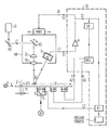
- the arrangement shown in the figure shows a light source LQ, preferably a light beam emits a laser beam L.
- the laser beam L reaches the measuring head MK via a deflection mirror US, which has a tilting mirror KS and a lens system in the optical path of the laser beam L.
- the lens system consists of a focusing lens FL, in order to focus the laser beam L in the vertical beam direction on the surface of the plate Pl to be centered, and a cylindrical lens ZL, through which the laser beam L is focused in the form of a line. Line focusing is performed to make the device insensitive to dust and surface damage to the plate.
- the tilting mirror KS provided to facilitate the evaluation oscillates at a relatively low frequency, so that the light spot is moved back and forth on the plate P1 by about 200-300 ⁇ m in the radial direction.
- the measuring head MK has a detector D, which is arranged for optimal reception of the radiation in the direction of a diffraction order of the information tracks acting as a diffraction grating.
- the laser beam L emitted by the measuring head MK is only diffracted when it strikes the information part IT of the plate P1 provided with information tracks. On the other hand, when it hits the information-free part IFT, it is not diffracted, so that in this case the detector D cannot receive any radiation either.
- the measuring head MK and thus the laser beam L - focused on the plate P1. Moving from the information-free part IFT starting in the radial direction to the plate P1 to the beginning of the information part IT. Once the start of the information part IT has been found, the movement of the measuring head MK is controlled in such a way that the focused laser beam L is exactly on the boundary between information during a full disk revolution part IT and information-free part IFT.
- an electronic control circuit ST controlled by the detector D with the signal S1 is provided.
- the signal S1 at the input E1 of the electronic control circuit ST is converted via the amplifier V into the signal S2, which reaches the measuring head drive MKA via the output A1 of the electronic control circuit ST, so that the focused laser beam L during a full disk revolution on the boundary between Information part IT and information-free part IFT is held.
- the control signals S2 emitted to the measuring head drive MKA during a full disk revolution are simultaneously stored in a memory SP.
- the control signals S2 are converted into control commands for readjustment of the translatory movement of the plate P1 in the x-y plate plane necessary for centering.
- the drive x-an for the movement of the plate P1 in the x direction is controlled via the output A2 of the electronic control circuit ST and the drive y-an for the movement in the y direction is controlled via the output A3.
- the rotary drive ROT-AN controlled by the motor M for the plate P1 has a switch S for setting the direction of rotation.
- the plate Pl leads to the boundary between information when setting the focused laser beam part of IT and information-free part of IFT complete full rotation, for example clockwise.
- switch position 2 the plate P1 is brought back into the starting position to check the centering in the opposite direction of rotation.
- the signal measured during this return is fed via the input E2 of the electronic control circuit ST to a control device KE which, when the center Z is located, releases the punching out of the center hole M within adjustable tolerance limits.
- the punching device itself is not shown in the drawing.
Landscapes
- Physics & Mathematics (AREA)
- General Physics & Mathematics (AREA)
- Manufacturing Optical Record Carriers (AREA)
- Manufacturing Of Magnetic Record Carriers (AREA)
- Optical Recording Or Reproduction (AREA)
- Moving Of The Head For Recording And Reproducing By Optical Means (AREA)
- Gripping On Spindles (AREA)
- Paper (AREA)
- Supporting Of Heads In Record-Carrier Devices (AREA)
Priority Applications (1)
| Application Number | Priority Date | Filing Date | Title |
|---|---|---|---|
| AT81102248T ATE21547T1 (de) | 1980-03-31 | 1981-03-25 | Vorrichtung zum zentrieren fuer die herstellung eines mittellochs in platten. |
Applications Claiming Priority (2)
| Application Number | Priority Date | Filing Date | Title |
|---|---|---|---|
| DE3012433 | 1980-03-31 | ||
| DE3012433A DE3012433C1 (de) | 1980-03-31 | 1980-03-31 | Vorrichtung zum Zentrieren fuer die Herstellung eines Mittellochs in Platten |
Publications (3)
| Publication Number | Publication Date |
|---|---|
| EP0037073A2 true EP0037073A2 (fr) | 1981-10-07 |
| EP0037073A3 EP0037073A3 (en) | 1983-10-12 |
| EP0037073B1 EP0037073B1 (fr) | 1986-08-20 |
Family
ID=6098859
Family Applications (1)
| Application Number | Title | Priority Date | Filing Date |
|---|---|---|---|
| EP81102248A Expired EP0037073B1 (fr) | 1980-03-31 | 1981-03-25 | Dispositif de centrage pour la réalisation d'un trou au centre de disques |
Country Status (4)
| Country | Link |
|---|---|
| EP (1) | EP0037073B1 (fr) |
| JP (1) | JPS56153506A (fr) |
| AT (1) | ATE21547T1 (fr) |
| DE (1) | DE3012433C1 (fr) |
Cited By (3)
| Publication number | Priority date | Publication date | Assignee | Title |
|---|---|---|---|---|
| GB2200811A (en) * | 1987-02-09 | 1988-08-10 | Atomic Energy Authority Uk | Monitoring of displacement |
| EP0375882A1 (fr) * | 1988-10-28 | 1990-07-04 | Shin-Etsu Handotai Company, Limited | Dispositif pour la mesure de désaxage dans un appareil de tirage de cristaux |
| WO2013144354A1 (fr) * | 2012-03-29 | 2013-10-03 | Eusilex | Procede de fabrication d'un support de stockage d'informations |
Families Citing this family (4)
| Publication number | Priority date | Publication date | Assignee | Title |
|---|---|---|---|---|
| JPS57103111A (en) * | 1980-12-19 | 1982-06-26 | Pioneer Video Corp | Centering device for recording track of recording disk |
| JPS57103109A (en) * | 1980-12-19 | 1982-06-26 | Pioneer Video Corp | Centering device for recording track of recording disk |
| JPS57103110A (en) * | 1980-12-19 | 1982-06-26 | Pioneer Video Corp | Centering device for recording track of recording disk |
| JPH0373441A (ja) * | 1990-04-20 | 1991-03-28 | Sharp Corp | 光メモリ円板の製造方法 |
Family Cites Families (5)
| Publication number | Priority date | Publication date | Assignee | Title |
|---|---|---|---|---|
| US3740152A (en) * | 1971-06-23 | 1973-06-19 | Nippon Kogaku Kk | Device for detecting the boundary between different brightness regions of an object |
| US3915576A (en) * | 1974-09-30 | 1975-10-28 | Mca Disco Vision | Method and apparatus for centering a circular disc |
| JPS5263755A (en) * | 1975-11-22 | 1977-05-26 | Nippon Chemical Ind | Pattern line width measuring device |
| US4012148A (en) * | 1975-12-15 | 1977-03-15 | Marantette William F | Projection scope and positioning system |
| DE2800618C2 (de) * | 1978-01-07 | 1984-02-02 | Goetze Ag, 5093 Burscheid | Vorrichtung zum Ausrichten von unrunden Werkstücken |
-
1980
- 1980-03-31 DE DE3012433A patent/DE3012433C1/de not_active Expired
-
1981
- 1981-03-25 EP EP81102248A patent/EP0037073B1/fr not_active Expired
- 1981-03-25 AT AT81102248T patent/ATE21547T1/de not_active IP Right Cessation
- 1981-03-26 JP JP4326681A patent/JPS56153506A/ja active Granted
Cited By (5)
| Publication number | Priority date | Publication date | Assignee | Title |
|---|---|---|---|---|
| GB2200811A (en) * | 1987-02-09 | 1988-08-10 | Atomic Energy Authority Uk | Monitoring of displacement |
| EP0375882A1 (fr) * | 1988-10-28 | 1990-07-04 | Shin-Etsu Handotai Company, Limited | Dispositif pour la mesure de désaxage dans un appareil de tirage de cristaux |
| US5020907A (en) * | 1988-10-28 | 1991-06-04 | Shin-Etsu Handotai Company, Limited | Axis offset measuring device |
| WO2013144354A1 (fr) * | 2012-03-29 | 2013-10-03 | Eusilex | Procede de fabrication d'un support de stockage d'informations |
| FR2988895A1 (fr) * | 2012-03-29 | 2013-10-04 | Essilex | Procede de fabrication d'un support de stockage d'informations |
Also Published As
| Publication number | Publication date |
|---|---|
| EP0037073B1 (fr) | 1986-08-20 |
| ATE21547T1 (de) | 1986-09-15 |
| DE3012433C1 (de) | 1981-10-01 |
| EP0037073A3 (en) | 1983-10-12 |
| JPS56153506A (en) | 1981-11-27 |
| JPS6349285B2 (fr) | 1988-10-04 |
Similar Documents
| Publication | Publication Date | Title |
|---|---|---|
| DE3043378C2 (de) | Spurführungsservosteuervorrichtung für ein Lese- und Wiedergabegerät | |
| DE2541520C3 (de) | Einrichtung zum optischen Ausrichten des Abtastsystems auf einen Informationskanal einer Videoplatte | |
| DE3406629C2 (de) | Verfahren und Vorrichtung zur Fokuseinstellung eines Bildabtast- und -wiedergabesystems | |
| DE69320346T2 (de) | Gerät und verfahren zur prüfung der ätzung von optischen servo-informationen auf magnetischen medien | |
| DE2926140A1 (de) | Vorrichtung zur ermittlung der umfangsausbildung eines gegenstandes | |
| WO2000003833A1 (fr) | Procede et dispositif pour etalonner une machine d'usinage de pieces par laser | |
| DE3809804A1 (de) | Codierer | |
| DE2630381C2 (de) | Optischer Leser | |
| DE2607705C3 (de) | Vorrichtung zur optischen Wiedergabe von auf einer Platte aufgezeichneten Informationen | |
| DE3718956C2 (fr) | ||
| DE3538062A1 (de) | Lagemesseinrichtung | |
| EP0682226A2 (fr) | Dispositif pour vérifier l'état d'une surface | |
| DE3409177C2 (fr) | ||
| DE3023779A1 (de) | Verfahren zum feststellen der scharfeinstellung eines objektivs in bezug auf einen gegenstand und vorrichtung zur durchfuehrung des verfahrens | |
| EP0037073B1 (fr) | Dispositif de centrage pour la réalisation d'un trou au centre de disques | |
| DE2820482C2 (de) | Vorrichtung zum Scharfeinstellen eines optischen Auslesesystems | |
| DE3782895T2 (de) | Optischer lesekopf. | |
| DE3242002C2 (fr) | ||
| DE2658677A1 (de) | Informationstraeger, verfahren zu seiner herstellung sowie verfahren und vorrichtungen zum aufzeichnen und/oder wiedergeben von informationen mit hilfe des informationstraegers | |
| DE3802693C2 (fr) | ||
| DE1189744B (de) | Verfahren und Vorrichtung zum Erkennen gesprochener Worte | |
| DE3887726T2 (de) | Gerät für eine entfernbare Platte mit Regelung der Position der Rotation. | |
| DE2753782A1 (de) | Vorrichtung zum bestimmen der richtungskoordinaten eines entfernten objekts | |
| DE3405433C2 (de) | Optisches Abtastgerät zum Abtasten von Informationen | |
| DE3609064A1 (de) | Steuervorrichtung fuer den schreib/lesekopf einer aufnahme/wiedergabevorrichtung |
Legal Events
| Date | Code | Title | Description |
|---|---|---|---|
| PUAI | Public reference made under article 153(3) epc to a published international application that has entered the european phase |
Free format text: ORIGINAL CODE: 0009012 |
|
| AK | Designated contracting states |
Designated state(s): AT BE CH FR GB IT LU NL SE |
|
| 17P | Request for examination filed |
Effective date: 19811028 |
|
| PUAL | Search report despatched |
Free format text: ORIGINAL CODE: 0009013 |
|
| AK | Designated contracting states |
Designated state(s): AT BE CH FR GB IT LI LU NL SE |
|
| GRAA | (expected) grant |
Free format text: ORIGINAL CODE: 0009210 |
|
| AK | Designated contracting states |
Kind code of ref document: B1 Designated state(s): AT BE CH FR GB IT LI LU NL SE |
|
| REF | Corresponds to: |
Ref document number: 21547 Country of ref document: AT Date of ref document: 19860915 Kind code of ref document: T |
|
| ITF | It: translation for a ep patent filed | ||
| ET | Fr: translation filed | ||
| PGFP | Annual fee paid to national office [announced via postgrant information from national office to epo] |
Ref country code: AT Payment date: 19870312 Year of fee payment: 7 |
|
| PG25 | Lapsed in a contracting state [announced via postgrant information from national office to epo] |
Ref country code: LU Free format text: LAPSE BECAUSE OF NON-PAYMENT OF DUE FEES Effective date: 19870331 |
|
| PGFP | Annual fee paid to national office [announced via postgrant information from national office to epo] |
Ref country code: NL Payment date: 19870331 Year of fee payment: 7 |
|
| PLBE | No opposition filed within time limit |
Free format text: ORIGINAL CODE: 0009261 |
|
| STAA | Information on the status of an ep patent application or granted ep patent |
Free format text: STATUS: NO OPPOSITION FILED WITHIN TIME LIMIT |
|
| 26N | No opposition filed | ||
| PG25 | Lapsed in a contracting state [announced via postgrant information from national office to epo] |
Ref country code: LI Effective date: 19880331 Ref country code: CH Effective date: 19880331 |
|
| REG | Reference to a national code |
Ref country code: CH Ref legal event code: PL |
|
| PGFP | Annual fee paid to national office [announced via postgrant information from national office to epo] |
Ref country code: FR Payment date: 19890322 Year of fee payment: 9 |
|
| PG25 | Lapsed in a contracting state [announced via postgrant information from national office to epo] |
Ref country code: AT Effective date: 19890325 |
|
| PG25 | Lapsed in a contracting state [announced via postgrant information from national office to epo] |
Ref country code: SE Effective date: 19890326 |
|
| PGFP | Annual fee paid to national office [announced via postgrant information from national office to epo] |
Ref country code: GB Payment date: 19890331 Year of fee payment: 9 |
|
| PG25 | Lapsed in a contracting state [announced via postgrant information from national office to epo] |
Ref country code: NL Effective date: 19891001 |
|
| NLV4 | Nl: lapsed or anulled due to non-payment of the annual fee | ||
| PGFP | Annual fee paid to national office [announced via postgrant information from national office to epo] |
Ref country code: BE Payment date: 19900312 Year of fee payment: 10 |
|
| PG25 | Lapsed in a contracting state [announced via postgrant information from national office to epo] |
Ref country code: GB Effective date: 19900325 |
|
| ITTA | It: last paid annual fee | ||
| GBPC | Gb: european patent ceased through non-payment of renewal fee | ||
| PG25 | Lapsed in a contracting state [announced via postgrant information from national office to epo] |
Ref country code: FR Effective date: 19901130 |
|
| REG | Reference to a national code |
Ref country code: FR Ref legal event code: ST |
|
| PG25 | Lapsed in a contracting state [announced via postgrant information from national office to epo] |
Ref country code: BE Effective date: 19910331 |
|
| BERE | Be: lapsed |
Owner name: POLYGRAM G.M.B.H. Effective date: 19910331 |
|
| EUG | Se: european patent has lapsed |
Ref document number: 81102248.2 Effective date: 19900118 |