EP0037104A2 - Kupplung mit Reibungsmaterial aus pyrolytischem Kohlenstoff - Google Patents
Kupplung mit Reibungsmaterial aus pyrolytischem Kohlenstoff Download PDFInfo
- Publication number
- EP0037104A2 EP0037104A2 EP81102342A EP81102342A EP0037104A2 EP 0037104 A2 EP0037104 A2 EP 0037104A2 EP 81102342 A EP81102342 A EP 81102342A EP 81102342 A EP81102342 A EP 81102342A EP 0037104 A2 EP0037104 A2 EP 0037104A2
- Authority
- EP
- European Patent Office
- Prior art keywords
- friction
- carbon
- friction material
- fibers
- discs
- Prior art date
- Legal status (The legal status is an assumption and is not a legal conclusion. Google has not performed a legal analysis and makes no representation as to the accuracy of the status listed.)
- Withdrawn
Links
Images



Classifications
-
- F—MECHANICAL ENGINEERING; LIGHTING; HEATING; WEAPONS; BLASTING
- F16—ENGINEERING ELEMENTS AND UNITS; GENERAL MEASURES FOR PRODUCING AND MAINTAINING EFFECTIVE FUNCTIONING OF MACHINES OR INSTALLATIONS; THERMAL INSULATION IN GENERAL
- F16H—GEARING
- F16H48/00—Differential gearings
- F16H48/20—Arrangements for suppressing or influencing the differential action, e.g. locking devices
- F16H48/22—Arrangements for suppressing or influencing the differential action, e.g. locking devices using friction clutches or brakes
-
- B—PERFORMING OPERATIONS; TRANSPORTING
- B60—VEHICLES IN GENERAL
- B60T—VEHICLE BRAKE CONTROL SYSTEMS OR PARTS THEREOF; BRAKE CONTROL SYSTEMS OR PARTS THEREOF, IN GENERAL; ARRANGEMENT OF BRAKING ELEMENTS ON VEHICLES IN GENERAL; PORTABLE DEVICES FOR PREVENTING UNWANTED MOVEMENT OF VEHICLES; VEHICLE MODIFICATIONS TO FACILITATE COOLING OF BRAKES
- B60T1/00—Arrangements of braking elements, i.e. of those parts where braking effect occurs specially for vehicles
- B60T1/02—Arrangements of braking elements, i.e. of those parts where braking effect occurs specially for vehicles acting by retarding wheels
- B60T1/06—Arrangements of braking elements, i.e. of those parts where braking effect occurs specially for vehicles acting by retarding wheels acting otherwise than on tread, e.g. employing rim, drum, disc, or transmission or on double wheels
- B60T1/065—Arrangements of braking elements, i.e. of those parts where braking effect occurs specially for vehicles acting by retarding wheels acting otherwise than on tread, e.g. employing rim, drum, disc, or transmission or on double wheels employing disc
-
- C—CHEMISTRY; METALLURGY
- C04—CEMENTS; CONCRETE; ARTIFICIAL STONE; CERAMICS; REFRACTORIES
- C04B—LIME, MAGNESIA; SLAG; CEMENTS; COMPOSITIONS THEREOF, e.g. MORTARS, CONCRETE OR LIKE BUILDING MATERIALS; ARTIFICIAL STONE; CERAMICS; REFRACTORIES; TREATMENT OF NATURAL STONE
- C04B35/00—Shaped ceramic products characterised by their composition; Ceramics compositions; Processing powders of inorganic compounds preparatory to the manufacturing of ceramic products
- C04B35/71—Ceramic products containing macroscopic reinforcing agents
- C04B35/78—Ceramic products containing macroscopic reinforcing agents containing non-metallic materials
- C04B35/80—Fibres, filaments, whiskers, platelets, or the like
- C04B35/83—Carbon fibres in a carbon matrix
-
- F—MECHANICAL ENGINEERING; LIGHTING; HEATING; WEAPONS; BLASTING
- F16—ENGINEERING ELEMENTS AND UNITS; GENERAL MEASURES FOR PRODUCING AND MAINTAINING EFFECTIVE FUNCTIONING OF MACHINES OR INSTALLATIONS; THERMAL INSULATION IN GENERAL
- F16D—COUPLINGS FOR TRANSMITTING ROTATION; CLUTCHES; BRAKES
- F16D65/00—Parts or details
- F16D65/02—Braking members; Mounting thereof
- F16D65/12—Discs; Drums for disc brakes
- F16D65/127—Discs; Drums for disc brakes characterised by properties of the disc surface; Discs lined with friction material
-
- F—MECHANICAL ENGINEERING; LIGHTING; HEATING; WEAPONS; BLASTING
- F16—ENGINEERING ELEMENTS AND UNITS; GENERAL MEASURES FOR PRODUCING AND MAINTAINING EFFECTIVE FUNCTIONING OF MACHINES OR INSTALLATIONS; THERMAL INSULATION IN GENERAL
- F16D—COUPLINGS FOR TRANSMITTING ROTATION; CLUTCHES; BRAKES
- F16D69/00—Friction linings; Attachment thereof; Selection of coacting friction substances or surfaces
- F16D69/02—Composition of linings ; Methods of manufacturing
-
- F—MECHANICAL ENGINEERING; LIGHTING; HEATING; WEAPONS; BLASTING
- F16—ENGINEERING ELEMENTS AND UNITS; GENERAL MEASURES FOR PRODUCING AND MAINTAINING EFFECTIVE FUNCTIONING OF MACHINES OR INSTALLATIONS; THERMAL INSULATION IN GENERAL
- F16D—COUPLINGS FOR TRANSMITTING ROTATION; CLUTCHES; BRAKES
- F16D69/00—Friction linings; Attachment thereof; Selection of coacting friction substances or surfaces
- F16D69/02—Composition of linings ; Methods of manufacturing
- F16D69/023—Composite materials containing carbon and carbon fibres or fibres made of carbonizable material
-
- F—MECHANICAL ENGINEERING; LIGHTING; HEATING; WEAPONS; BLASTING
- F16—ENGINEERING ELEMENTS AND UNITS; GENERAL MEASURES FOR PRODUCING AND MAINTAINING EFFECTIVE FUNCTIONING OF MACHINES OR INSTALLATIONS; THERMAL INSULATION IN GENERAL
- F16D—COUPLINGS FOR TRANSMITTING ROTATION; CLUTCHES; BRAKES
- F16D69/00—Friction linings; Attachment thereof; Selection of coacting friction substances or surfaces
- F16D69/04—Attachment of linings
- F16D2069/0425—Attachment methods or devices
- F16D2069/045—Bonding
- F16D2069/0466—Bonding chemical, e.g. using adhesives, vulcanising
-
- F—MECHANICAL ENGINEERING; LIGHTING; HEATING; WEAPONS; BLASTING
- F16—ENGINEERING ELEMENTS AND UNITS; GENERAL MEASURES FOR PRODUCING AND MAINTAINING EFFECTIVE FUNCTIONING OF MACHINES OR INSTALLATIONS; THERMAL INSULATION IN GENERAL
- F16D—COUPLINGS FOR TRANSMITTING ROTATION; CLUTCHES; BRAKES
- F16D65/00—Parts or details
- F16D65/02—Braking members; Mounting thereof
- F16D65/12—Discs; Drums for disc brakes
- F16D65/125—Discs; Drums for disc brakes characterised by the material used for the disc body
- F16D65/126—Discs; Drums for disc brakes characterised by the material used for the disc body the material being of low mechanical strength, e.g. carbon, beryllium; Torque transmitting members therefor
-
- F—MECHANICAL ENGINEERING; LIGHTING; HEATING; WEAPONS; BLASTING
- F16—ENGINEERING ELEMENTS AND UNITS; GENERAL MEASURES FOR PRODUCING AND MAINTAINING EFFECTIVE FUNCTIONING OF MACHINES OR INSTALLATIONS; THERMAL INSULATION IN GENERAL
- F16H—GEARING
- F16H48/00—Differential gearings
- F16H48/20—Arrangements for suppressing or influencing the differential action, e.g. locking devices
- F16H2048/202—Arrangements for suppressing or influencing the differential action, e.g. locking devices using freewheel clutches
-
- F—MECHANICAL ENGINEERING; LIGHTING; HEATING; WEAPONS; BLASTING
- F16—ENGINEERING ELEMENTS AND UNITS; GENERAL MEASURES FOR PRODUCING AND MAINTAINING EFFECTIVE FUNCTIONING OF MACHINES OR INSTALLATIONS; THERMAL INSULATION IN GENERAL
- F16H—GEARING
- F16H48/00—Differential gearings
- F16H48/06—Differential gearings with gears having orbital motion
- F16H48/08—Differential gearings with gears having orbital motion comprising bevel gears
-
- F—MECHANICAL ENGINEERING; LIGHTING; HEATING; WEAPONS; BLASTING
- F16—ENGINEERING ELEMENTS AND UNITS; GENERAL MEASURES FOR PRODUCING AND MAINTAINING EFFECTIVE FUNCTIONING OF MACHINES OR INSTALLATIONS; THERMAL INSULATION IN GENERAL
- F16H—GEARING
- F16H48/00—Differential gearings
- F16H48/20—Arrangements for suppressing or influencing the differential action, e.g. locking devices
- F16H48/295—Arrangements for suppressing or influencing the differential action, e.g. locking devices using multiple means for force boosting
-
- Y—GENERAL TAGGING OF NEW TECHNOLOGICAL DEVELOPMENTS; GENERAL TAGGING OF CROSS-SECTIONAL TECHNOLOGIES SPANNING OVER SEVERAL SECTIONS OF THE IPC; TECHNICAL SUBJECTS COVERED BY FORMER USPC CROSS-REFERENCE ART COLLECTIONS [XRACs] AND DIGESTS
- Y10—TECHNICAL SUBJECTS COVERED BY FORMER USPC
- Y10S—TECHNICAL SUBJECTS COVERED BY FORMER USPC CROSS-REFERENCE ART COLLECTIONS [XRACs] AND DIGESTS
- Y10S475/00—Planetary gear transmission systems or components
- Y10S475/901—Particular material
- Y10S475/902—Nonmetallic
-
- Y—GENERAL TAGGING OF NEW TECHNOLOGICAL DEVELOPMENTS; GENERAL TAGGING OF CROSS-SECTIONAL TECHNOLOGIES SPANNING OVER SEVERAL SECTIONS OF THE IPC; TECHNICAL SUBJECTS COVERED BY FORMER USPC CROSS-REFERENCE ART COLLECTIONS [XRACs] AND DIGESTS
- Y10—TECHNICAL SUBJECTS COVERED BY FORMER USPC
- Y10T—TECHNICAL SUBJECTS COVERED BY FORMER US CLASSIFICATION
- Y10T428/00—Stock material or miscellaneous articles
- Y10T428/29—Coated or structually defined flake, particle, cell, strand, strand portion, rod, filament, macroscopic fiber or mass thereof
- Y10T428/2913—Rod, strand, filament or fiber
- Y10T428/2918—Rod, strand, filament or fiber including free carbon or carbide or therewith [not as steel]
Definitions
- This invention relates to a friction material for clutches and brakes and, in particular, to a friction material for wet clutches and brakes.
- the invention further relates to a friction material for use in limited slip or locking differentials and for use in hoist load brakes.
- friction material of the present invention is relatively inexpensive, exhibits a high level of these desirable characteristics, and eliminates or virtually eliminates chatter when used in wet clutches and brakes.
- a form of the friction material of the present invention is illustrated for use in a locking differential of the type disclosed in U.S. Patent 3,831,462, issued to Jerry F. Baremor and a limited slip differential of the type disclosed in U.S. Patent 3,624,717, issued to Richard K. Brubaker.
- the Baremor differential includes a multiple disc friction clutch which is applied to retard relative rotation between driven axles only when the relative rotation exceeds a predetermined level.
- the Brubaker differential includes a pair of multiple disc friction clutches which are continuously applied by relatively light spring forces and by parting forces acting between the differential side gears and pinions.
- the friction material of the present invention is readily traced to the Aerospace Industry. Aerospace needs, particularly in the past three decades, have fostered the development of many exotic materials which are commerically successful in the aerospace industry but which fail to achieve commercial success in other industries due to the high cost, e.g., the automotive industry.
- One such material has been high carbon density composite material produced by chemical vapor deposition (CVD) of carbon or graphite on a precursor cloth substrate.
- the substrate may be a felt or a woven fabric composed of carbon or graphite.
- Carbon materials produced by CVD are generally referred to as pyrolytic carbon or graphite.
- carbon and graphite materials produced by CVD on a carbon or graphite cloth will be referred to as pyrolytic carbon composite material unless explicitly stated otherwise.
- a dry brake or clutch is defined as a brake or clutch wherein the friction surfaces are dry and a wet brake or clutch is defined as a brake or clutch wherein the friction surfaces are lubricated or cooled by direct contact with a liquid.
- Unsatisfactory levels of chatter were obtained with dry brakes having one friction surface of the composite material and the other of steel or iron.
- U.S. Patent 3,991,248, issued to Dieter W. Bauer in 1975, provides one example of the time-consuming process for CVD infiltrating multiple layers of cloth substrate to a high carbon density.
- the substrate may consist of multiple layers of a rayon precursor graphite cloth.
- the cloth layers are abraded on both sides to raise the nap of the cloth, cut into a desired shape, and stacked in layers in a compacting fixture.
- the cloth is then CVD infiltrated for as much as several hundred hours in a batch furnace.
- the CVD carbon infiltrated between the layers provides a matrix penetrated by the nap fibers to increase the layer-to-layer bond or shear strength between the layers.
- Example 1 Sample 5, of the Bauer patent, twenty- five layers of abrated cloth are cut into annular discs having an O.D. of 3.650 inches (9.271 cm) and an I.D. of 0.750 inches (1.905 cm) and then stacked in the fixture of FIGURE 1.
- the layers are compacted or compressed by the fixture to a total substrate thickness of 0.350 inches and then CVD infiltrated for ten hours and then for 160 hours.
- the ten-hour infiltration run, according to Table 2 increased the density from 0.717 grams per cubic centimeter to 1.070 grams per cubic centimeter, a carbon density increase of 0.0253 grams per cubic centimeter per hour of infiltration time.
- the 160-hour infiltration run increased the density from 1.070 grams per cubic centimeter to 1.590 grams per cubic centimeter, a carbon density increase of only 0.00325 grams per cubic centimeter per hour of infiltration time.
- the partially infiltrated substrate was removed from the fixture and machined on all of its sides to remove bottleneck pores which prevent or impede further infiltration. After machining, the substrate was ultrasonically cleaned in acetone prior to continued infiltration.
- U. S. Patent 3,897,582 issued to Eugene L. Olcott in 1975, provides a second example of a process for making a pyrolytic carbon composite friction material for an aircraft brake.
- the material is formed by progressively positioning a continuous or a plurality of continuous refractory strands on a heated mandrel and simultaneously pyrolyzing pyrolysis gases onto the strand(s) at about the point of positioning contact of the strand(s) on the mandrel or on previously positioned strands to nucleate pyrolytic graphite.
- One object of this process is to provide a material having few or a minimum number of voids or pores which substantially reduce the density of the material.
- pyrolytic carbon composite material having multiple layers of cloth substrate highly densified by CVD infiltration provides chatter-free results when run against a metal, such as steel or iron, in a wet clutch or brake.
- This discovery reduces the amount of composite material required for a given clutch or brake and therefore reduces costs.
- the material, when used in wet clutches and brakes, seems to be insensitive to the type of lubricating or cooling oil used. For example, many friction materials are relatively chatter-free when used with extreme high pressure oils but chatter unacceptably when used with light pressure oils.
- the pyrolytic carbon composite material may be formed of a single layer of cloth substrate or two or three interwoven layers of fabric CVD infiltrated for relatively short periods of time compared to the infiltration time periods taught in the Bauer patent.
- excellent results have been obtained with single layers of square weave fabrics CVD infiltrated for several minutes by a process taught in U.S. Patent 3,944,686, issued to Robert W. Froberg.
- the Froberg patent which is incorporated herein by reference, discloses a process for making electrodes for use in fuel cells.
- the process unlike the batch process in the Bauer patent, is a continuous process wherein relatively long strips of precursor cloth (felt or woven fabric) continuously moves through a CVD infiltrating furnace in conveyor belt fashion.
- precursor cloth felt or woven fabric
- the finished material is readily recognized as a fabric, is relatively flexible, has open or unfilled meshes, and is pervious to light.
- the specific process for making this quickly infiltrated material forms no part of the present invention, e.g., the material may be made in batch process furnaces or continuous process furnaces.
- An object of this invention is to provide an improved friction material for brakes and clutches.
- Another object of this invention is to provide a friction material having improved operating characteristics in a wet clutch or brake.
- Another object of this invention is to provide a friction material having a surface which improves the materials bonding to a support member.
- Another object of this invention is to provide an improved friction material which virtually eliminates clutch chatter in locking and limited slip differentials.
- the friction material includes a meshed cloth formed of carbon fibers and pyrolytic carbon deposited on the fibers by chemical vapor deposition to form a pyrolytic carbon composite friction material having a relatively open mesh.
- a clutch or brake includes at least two members mounted for relative rotation and each having a friction surface rotatable therewith and confronting each other, means to frictionally engage the surfaces to retard the relative rotation, a cooling liquid in contact with the surfaces, and at least one of the surfaces being defined by a pyrolytic carbon composite friction material.
- the members of the above clutch or brake are formed from metal and the other friction surface is defined by the metal surface of the other member.
- the pyrolytic carbon composite friction material defining the one friction surface in the above two features is adhesively bonded to its respective member and includes a meshed cloth formed of carbon fibers and pyrolytic carbon deposited on the fibers by chemical vapor deposition to form a composite friction material having a readily visible mesh readily penetrated by the adhesive.
- a differential includes a casing mounted for rotation in a liquid lubricant bath, first and second side gears mounted for rotation in the casing for rotation relative to each other and relative to the casing, first and second sets of interleaved metal discs, respectively, rotatable with the casing and at least one of the gears and having mutually facing friction surfaces, and means to functionally engage the mutually facing surfaces to retard the relative rotation; one of each of the mutually facing friction surfaces are defined by the metal of its respective disc and the other of each of the mutually facing surfaces are defined by a pyrolytic carbon composite friction material bonded to its respective disc; and the pyrolytic carbon composite friction material is defined by a single layer of woven fabric formed of carbon fibers and pyrolytic carbon deposited on the fibers by chemical vapor deposition.
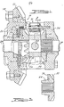
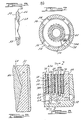
- the friction material of the present invention is shown for use in the locking differential mechanism 10 of FIGURES 1 - 8 and in the limited slip differential 11 of FIGURE 13.
- the differential mechanism 10 is of a type more fully described in U. S. Patent 3,831,462 issued to Jerry F. Baremor.
- the differential mechanism 11 is of a type more fully described in U. S. Patent 3,624,717 issued to Richard K. Brubaker. The specifications of these patents are hereby incorporated by reference into this application.
- mechanism 10 is rotatably supported in an unshown differential housing, that the housing defines a reservoir containing an oil for lubricating the mechanism in a conventional manner, and that mechanism 10 includes an input ring gear 12 secured to a rotatable casing 14, a differential gear train 16, and a regenerative self-energizing clutch assembly 18.
- Casing 14 includes a pair of support portions adapted to be received for rotation in bearings of the differential housing, not shown.
- the casing further includes a wall 20 defining an annular thrust surface 22 and another wall 24. Walls 20 and 24 define a chamber 26 for gear train 16 and clutch 18.
- gear train 16 The purpose of gear train 16 is to transmit rotary motion from casing 14 to a pair of output shafts 28 and 30.
- the gear train includes a pair of beveled side gears 32 and 34 and beveled pinion planetary gears 36 (FIGURE 2) disposed between and in meshing engagement with the side gears.
- the side gears are retained against outward movement by a thrust sleeve 38 and thrust washers 40 and 42.
- Pinion gears 36 are rotatably supported by casing 14 by means of a pinion shaft 44 extending across the gear chamber 26.
- Self-energizing clutch 18 is of the friction disc type and is operable between a disengaged condition wherein the axle shafts 28 and 30 are freely rotatable relative to each other and an engaged condition wherein the clutch 18 drivingly interconnects the axle shafts through casing 14 and gears 32, 34, and 36 to retard relative rotation therebetween.
- Clutch 18 includes two separate and distinct clutch portions. One portion is “active” to provide regenerative self-engaging forces for fully actuating the clutch mechanism while the other portion is “inactive” and merely increases total torque capacity after actuation.
- the "active" portion (FIGURES 1 and 8) of clutch 18 includes a cam 46 and interleaved clutch discs 48 and 50.
- Cam 46 includes an annular thrust surface 52.
- Clutch discs 48 are mounted for positive rotation with casing 14 by means of tabs 54 received in recesses 56 in casing 14 (FIGURE 7). This particular mounting arrangement is more clearly shown in U. S. Patent 3,052,137, issued to Robert c. Russell.
- Clutch discs 50 are mounted for positive rotation with cam 46 by means of a spline engagement 58.
- the “inactive” portion (FIGURES 1 and 8) of clutch 18 is provided to give increased torque transmitting capacity to the clutch and includes a plurality of alternatively interleaved discs 60 and 62.
- Discs 60 are generally identical in structure and mounting arrangement to discs 48 of the "active" portion and are likewise configured for positive rotation with casing 14.
- Discs 62 are mounted for positive rotation with side gear 32 by means of a spline engagement 64.
- the number of "active" discs is preferably greater than two and less than ten as more fully discussed in U. S. Patent 3,831,462.
- Cam 46 is drivingly connected to side gear 32 by wedging ramp surfaces 68 and 70 formed on the cam and the side gear respectively (FIGURES 3 to 6). These surfaces 68 and 70 serve to move the friction discs 48, 50, 60, and 62 into engagement when relative rotational movement between the side gears and the casing is induced. When the friction discs are in a fully engaged position (FIGURE 1), relative rotation is prevented by static friction forces acting between mutually facing surfaces on the discs.
- An actuator 72 having a splined shaft 74 drivingly engaged in gear teeth 76 of cam 46 is mounted for rotation with casing 14.
- the actuator is of the type more fully described in U. S. Patent RE 28,004, issued to William C. Ottemann. The specification of that patent is hereby incorporated by reference into this application. For the present, it is sufficient to state that when a predetermined rate of slip occurs betwee casing 14 and the side gears, actuator 72 is operable to retard cam 46 slightly relative to side gear 32, thereby squeezing the discs together.
- Actuator 72 thus provides an initial actuating force which, although relatively small, is sufficient to retard movement of cam 46 relative to side gear 32 by virtue of the drive connection of the gear teeth 76 and the spline on shaft 74.
- the abutting engagement of the sloping portions of the same surfaces 68 against similarly sloping portions of the surfaces 70 of side gear 32 causes an axially directed force to be applied against cam 46 thus reducing the distance between thrust surfaces 22 and 52 and causing frictional engagement of the mutually facing surfaces of the discs. Since the initial actuating force is provided by actuator 72 and is insufficient by itself to effect operation of clutch 18, the self-energizing characteristic of clutch 18 is necessary to complete the lockup of side gear 32 relative to casing 14.
- Discs 48, 50, 60, and 62 are flat steel discs which each, respectively, have relatively smooth, oppositely facing, annular surfaces 48a, 50a, 60a, and 62a.
- Surfaces 48a and 60a have a pyrolytic carbon composite material 78 bonded thereon to define annular friction surfaces 78a which in general run against mutually facing steel friction surfaces defined by surfaces 50a and 62a.
- material 78 may also be bonded to surfaces 50a and 62a.
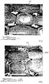
- Material 78 may be formed of multiple layers of carbon or graphite cloth substrate highly densified by CVD infiltration. However, the material is preferably formed of a single layer of carbon or graphite cloth substrate CVD infiltrated for relatively short periods of time. Samples of the material, bonded to steel discs, are shown in magnified views of FIGURES 9 - 12. The material in FIGURES 9 and 10 is unworn and that of FIGURES 11 and 12 is in two different stages of wear.
- the material in FIGURES 9 and 10 is a 0.016 inch thick, single layer, plain weave, Polyacrilonitrile (PAN) based, graphite fabric densified by the continuous process taught in the previously mentioned patent to Froberg and manufactured by the Minerals, Pigments and Metals Division of Pfizer, Inc.
- the coarse fabric texture of the material is readily discerned as well as the yarns and many of the fibers or filaments defining the yarns.
- extruded adhesive is clearly visible between some of the mesh defined by the yarns.
- the adhesive penetrates the mesh but does not extrude completely through to the friction face of the material.
- the rather rough texture of the fabric and the open mesh are readily gripped by the adhesive to form a strong bond. Excellent bonds have been obtained with 3M Brand, AF15, High Temperature Thermo-Set Adhesive applied 0.003 inches thick and cured at 350°F to 400°F under a 150 psi load for one hour.
- FIGURES 11 and 12 The material of FIGURES 11 and 12 is a 0.028 inch thick, single layer, plain weave, rayon based, graphite fabric densified by batch process and manufactured by the Engineering Systems Division of the B. F. Goodrich Company.
- mechanism 11 is rotatably supported in an unshown differential housing, that the housing defines a. reservoir containing an oil for lubricating the mechanism in a conventional manner, and that mechanism 11 includes an input ring gear 80 secured to a rotatable casing 82, a differential gear train 84, and a pair of clutch assemblies 86 and 88.
- Casing 82 includes left and right casing members 90 and 92 secured together by a plurality of bolts 94, a pair of support portions 90a and 92a adapted to be received for rotation in bearings of the differential housing, not shown, and annular thrust surfaces 90b and 92b defining a chamber 96 for gear train 84 and clutch assemblies 86 and 88.
- gear train 84 The purpose of gear train 84 is to transmit rotary motion from casing 82 to a pair of output shafts 98 and 100.
- the gear train includes a pair of beveled sided gears 102 and 104 and two or more beveled pinion planetary gears 106 disposed between and in meshing engagement with the side gears.
- Each pinion gear is rotatably supported in casing 82 by a pinion shaft 108.
- Side gears 102 and 104 are slideably splined to their respective output shafts and define annular thrust surfaces 102a and 104a.
- Clutch assemblies 86 and 88 each include a plurality of interleaved discs 110 and 112 interposed between the respective annular thrust surfaces defined by the side gears and the casing members.
- Discs 110 are slideably splined to the respective output shaft and discs 112 are slideably splined to casing 82 in a manner similar to the way tabs 54 are received by recesses 56 in FIGURE 7.
- a pair of retention devices 114 and 116 Disposed between the inboard faces of the side gears is a pair of retention devices 114 and 116 which cooperate with circumferential grooves 98a and 100a in shafts 98 and 100 in a manner to prevent withdrawal of the shafts from the differential case.
- Biasing springs 118 and 120 are provided between the retention devices to exert a preload force on the side gears to urge the clutch discs into engagement so that the discs will transmit a predetermined amount of torque from the casing to the output shafts or tend to rotate both output shafts even when there is little or no reaction force provided by one of the output shafts.
- the clutch discs are further biased into engagement in proportion to the amount of torque being transmitted to the side gears by the pinions due to parting forces resulting between pinion gear teeth in mesh with slide gear teeth.
- Discs 110 and 112 like discs 48, 50, 60 and 62, are flat steel discs having relatively smooth, oppositely facing, annular surfaces 110a and 112a.
- Surfaces 112a have the pyrolytic carbon composite material 78' bonded thereon to define annular friction surfaces 78a' which in general runs agains surfaces 110a. Alternately, material 78' may also be bonded to surfaces 110a.
- Material 78' is the same as material 78 described in connection with the locking differential and is bonded to the discs in the same manner.
- the single woven layers of the quickly densified material of FIGURES 9 - 12 may include two or three tightly interwoven layers of fabric or may be a felt cloth of carbon or graphite fibers.
- the following claims are intended to cover the inventive portions of the preferred embodiments and modifications believed to be within the spirit of the invention.
Landscapes
- Engineering & Computer Science (AREA)
- General Engineering & Computer Science (AREA)
- Chemical & Material Sciences (AREA)
- Mechanical Engineering (AREA)
- Ceramic Engineering (AREA)
- Composite Materials (AREA)
- Materials Engineering (AREA)
- Chemical Kinetics & Catalysis (AREA)
- Manufacturing & Machinery (AREA)
- Transportation (AREA)
- Structural Engineering (AREA)
- Organic Chemistry (AREA)
- Braking Arrangements (AREA)
- Mechanical Operated Clutches (AREA)
- Carbon And Carbon Compounds (AREA)
- Chemical Or Physical Treatment Of Fibers (AREA)
- Retarders (AREA)
Applications Claiming Priority (2)
| Application Number | Priority Date | Filing Date | Title |
|---|---|---|---|
| US134842 | 1980-03-28 | ||
| US06/134,842 US4700823A (en) | 1980-03-28 | 1980-03-28 | Clutch with pyrolytic carbon friction material |
Publications (2)
| Publication Number | Publication Date |
|---|---|
| EP0037104A2 true EP0037104A2 (de) | 1981-10-07 |
| EP0037104A3 EP0037104A3 (de) | 1981-11-25 |
Family
ID=22465265
Family Applications (1)
| Application Number | Title | Priority Date | Filing Date |
|---|---|---|---|
| EP81102342A Withdrawn EP0037104A3 (de) | 1980-03-28 | 1981-03-27 | Kupplung mit Reibungsmaterial aus pyrolytischem Kohlenstoff |
Country Status (3)
| Country | Link |
|---|---|
| US (1) | US4700823A (de) |
| EP (1) | EP0037104A3 (de) |
| JP (1) | JPS56150634A (de) |
Cited By (6)
| Publication number | Priority date | Publication date | Assignee | Title |
|---|---|---|---|---|
| AT386467B (de) * | 1982-05-18 | 1988-08-25 | Pesendorfer Johann | Bremsschuh fuer rollbahnwaegen und rutschbahnwaegen od.dgl. |
| US4846325A (en) * | 1987-11-10 | 1989-07-11 | Eaton Corporation | Friction brake for variable speed viscous fan control |
| EP0619444A1 (de) * | 1993-03-10 | 1994-10-12 | Eaton Corporation | Einstellbares Sperrdifferential |
| EP0762009A1 (de) * | 1995-09-08 | 1997-03-12 | General Motors Corporation | Reibungsmaterial auf Kohlenstoffbasis für Dauerrutschbetrieb bei Kraftfahrzeugen |
| EP1039167A1 (de) * | 1999-03-23 | 2000-09-27 | Eaton Corporation | Reibungsmaterial für Getriebeträgheitsbremse und Konuskupplung |
| EP3418100A1 (de) * | 2008-05-06 | 2018-12-26 | GKN Automotive Ltd. | Antriebsstrang für ein kraftfahrzeug mit zuschaltbarer sekundärachse |
Families Citing this family (102)
| Publication number | Priority date | Publication date | Assignee | Title |
|---|---|---|---|---|
| US4828089A (en) * | 1985-05-07 | 1989-05-09 | Eaton Corporation | Brake/clutch with direct liquid cooling |
| US4805486A (en) * | 1986-06-04 | 1989-02-21 | Tochigifujisangyo Kabushiki Kaisha | Locking differential gear assembly |
| JPH0525946Y2 (de) * | 1987-01-13 | 1993-06-30 | ||
| US4778548A (en) * | 1987-07-24 | 1988-10-18 | Fox Joseph R | Bonding woven carbon fabric friction materials |
| US4831894A (en) * | 1988-03-14 | 1989-05-23 | Eaton Corporation | Transmission input section |
| US4882951A (en) * | 1988-03-14 | 1989-11-28 | Eaton Corporation | Auxiliary transmission input section |
| US4844218A (en) * | 1988-03-28 | 1989-07-04 | Eaton Corporation | Friction material configuration |
| US5033596A (en) * | 1988-03-28 | 1991-07-23 | Genise Thomas A | Resilient friction material |
| BR8901502A (pt) * | 1988-03-28 | 1989-11-14 | Eaton Corp | Dispositivo absorvedor de energia,metodo para prover um membro rigido com superficie de friccao resiliente e conjunto de embreagem |
| US5091041A (en) * | 1989-03-22 | 1992-02-25 | Eaton Corporation | Bonding apparatus for bonding friction material |
| US5221401A (en) * | 1989-03-22 | 1993-06-22 | Eaton Corporation | Method for bonding friction material onto a frustoconical surface |
| AU631085B2 (en) * | 1989-03-22 | 1992-11-12 | Eaton Corporation | Fixture and method for bonding friction material |
| US4997067A (en) * | 1989-06-26 | 1991-03-05 | Fenner America, Inc. | Friction apparatus |
| US5025906A (en) * | 1990-07-26 | 1991-06-25 | Eaton Corporation | Remote sensing viscous fluid coupling |
| US5030865A (en) * | 1990-07-26 | 1991-07-09 | Eaton Corporation | Self powered remote viscous fluid coupling |
| US5161423A (en) | 1990-12-24 | 1992-11-10 | Eaton Corporation | Self-energizing synchronizer for equalizing shift time and effort of a multi-ratio transmission |
| US5111922A (en) * | 1990-12-24 | 1992-05-12 | Eaton Corporation | Pre-energizer for a synchronizer |
| US5092439A (en) * | 1990-12-24 | 1992-03-03 | Eaton Corporation | Synchronizer with deep splines & improved boost ramps |
| US5086897A (en) * | 1990-12-24 | 1992-02-11 | Eaton Corporation | Pre-energizer pins for a synchronizer |
| US5092438A (en) * | 1990-12-24 | 1992-03-03 | Eaton Corporation | Synchronizer with self-energizing |
| JP2582215Y2 (ja) * | 1992-07-23 | 1998-09-30 | エヌエスケー・ワーナー株式会社 | 摩擦係合装置 |
| GB9220603D0 (en) * | 1992-09-30 | 1992-11-11 | Dunlop Ltd | Toughened carbon composite brake discs |
| US6001750A (en) * | 1993-08-04 | 1999-12-14 | Borg-Warner Automotive, Inc. | Fibrous lining material comprising a primary layer having less fibrillated aramid fibers, carbon fibers, carbon particles and a secondary layer comprising carbon particles |
| US5856244A (en) * | 1993-08-04 | 1999-01-05 | Borg-Warner Automotive, Inc. | Carbon deposit friction lining material |
| US5998307A (en) * | 1993-08-04 | 1999-12-07 | Borg-Warner Autotive, Inc. | Fibrous lining material comprising a primary layer having less fibrillated aramid fibers and synthetic graphite and a secondary layer comprising carbon particles |
| US6130176A (en) * | 1993-08-04 | 2000-10-10 | Borg-Warner Inc. | Fibrous base material for a friction lining material comprising less fibrillated aramid fibers and carbon fibers |
| US5753356A (en) * | 1993-08-04 | 1998-05-19 | Borg-Warner Automotive, Inc. | Friction lining material comprising less fibrillated aramid fibers and synthetic graphite |
| US6065579A (en) * | 1994-09-30 | 2000-05-23 | Select Powertrain Technologies Corp. | Synchronizer blocker rings used in manual transmissions |
| US5615758A (en) | 1994-09-30 | 1997-04-01 | Nels; Terry E. | Fabric arrangement and method for controlling fluid flow |
| FR2729726B1 (fr) * | 1995-01-23 | 1997-04-18 | Antonov Automotive Europ | Embrayage multi-disques, transmission automatique ainsi equipee et procede de realisation |
| US5577581A (en) * | 1995-02-08 | 1996-11-26 | Eaton Corporation | Coupling assembly |
| US5895716A (en) * | 1995-07-18 | 1999-04-20 | The B.F. Goodrich Company | Wet friction materials, methods of making them, and apparatus containing the same |
| US5680921A (en) * | 1996-02-07 | 1997-10-28 | Borg-Warner Automotive, Inc. | Transmission band assembly |
| US5738195A (en) | 1996-09-16 | 1998-04-14 | Eaton Corporation | Pin-type synchronizer |
| US5865287A (en) | 1996-09-16 | 1999-02-02 | Eaton Corporation | Pin-type synchronizer |
| US5769198A (en) | 1996-09-16 | 1998-06-23 | Eaton Corporation | Pin-type synchronizer |
| US5738196A (en) | 1996-09-16 | 1998-04-14 | Eaton Corporation | Pin-type synchronizer |
| US5789065A (en) * | 1996-10-11 | 1998-08-04 | Kimberly-Clark Worldwide, Inc. | Laminated fabric having cross-directional elasticity and method for producing same |
| US5851588A (en) * | 1996-11-21 | 1998-12-22 | Eaton Corporation | Method for making open-mesh carbon-fiber-reinforced carbon composite material |
| US5952249A (en) * | 1996-12-17 | 1999-09-14 | Textron Systems Corporation | Amorphous carbon-coated carbon fabric wet friction material |
| FR2760504B1 (fr) * | 1997-03-06 | 1999-04-23 | Valeo | Garniture de frottement a porosite controlee destinee a equiper un dispositif mettant en oeuvre un frottement en milieu liquide |
| US5858511A (en) * | 1997-03-11 | 1999-01-12 | Eaton Corporation | Grooved friction material, method of making same, and wet friction member using grooved friction material |
| US6102178A (en) * | 1997-05-30 | 2000-08-15 | Eaton Corporation | Viscous actuated ball ramp clutch |
| DE69800362T2 (de) | 1997-05-30 | 2001-05-17 | Eaton Corp., Cleveland | Flüssigkeitsreibungsbetätigte Kugel-Rampen-Kupplung |
| US5967276A (en) * | 1997-05-30 | 1999-10-19 | Eaton Corporation | Viscous actuated ball ramp clutch and improved housing therefor |
| US5901824A (en) | 1997-08-11 | 1999-05-11 | Eaton Corporation | Synchronizer including radially-moveable self-energizing member |
| US5901823A (en) | 1997-08-11 | 1999-05-11 | Eaton Corporation | Synchronizer including radially-moveable, resiliently-biased self-energizing member |
| US5911643A (en) * | 1998-01-02 | 1999-06-15 | Eaton Corporation | Differential gear mechanism and improved ball-ramp actuation thereof |
| US6022295A (en) * | 1998-11-12 | 2000-02-08 | Eaton Corporation | Touch point identification for vehicle master clutch |
| US5980428A (en) * | 1998-11-13 | 1999-11-09 | Eaton Corporation | Vehicle launch automated master clutch control |
| US6071211A (en) * | 1998-11-18 | 2000-06-06 | Eaton Corporation | Idle drive torque control for automated vehicle master clutch |
| US6726962B1 (en) | 1998-12-18 | 2004-04-27 | Messier-Bugatti Inc. | Method for forming composite articles |
| US6083134A (en) * | 1999-02-18 | 2000-07-04 | Eaton Corporation | Electronically actuated locking differential |
| DE19906980B4 (de) * | 1999-02-19 | 2013-09-19 | Borg-Warner Automotive Gmbh | Eingriffsteil für ein Kraftübertragungsaggregat |
| US6132877A (en) * | 1999-03-09 | 2000-10-17 | General Motors Corporation | High density, low porosity, carbon composite clutch material |
| US6277769B1 (en) * | 1999-05-05 | 2001-08-21 | S.K.. Wellman Corp. | High energy friction product |
| BR9907360A (pt) | 1999-11-12 | 2001-06-26 | Eaton Corp | Sincronizador tipo anel de bloqueio de ação dupla |
| GB2357125A (en) | 1999-12-08 | 2001-06-13 | Eaton Corp | Synchronizer with a resilient force limiting ramp members and blocker teeth |
| GB2357126A (en) | 1999-12-08 | 2001-06-13 | Eaton Corp | Synchronizer with force limiter which prevents damage |
| US6543596B2 (en) | 2000-04-24 | 2003-04-08 | Borgwarner, Inc. | Multi-disk friction device having low-drag characteristics |
| GB2361980A (en) | 2000-05-05 | 2001-11-07 | Eaton Corp | Dry clutch control system using idle drive torque so as to provide vehicle crawl speed |
| US7033663B1 (en) | 2000-06-27 | 2006-04-25 | Eaton Corporation | Functionally graded friction material |
| US6555173B1 (en) | 2000-11-08 | 2003-04-29 | Honeywell International Inc. | Carbon barrier controlled metal infiltration layer for enhanced oxidation protection |
| US6572712B2 (en) | 2000-12-14 | 2003-06-03 | Waupaca Foundry, Inc. | Compacted graphite iron brake drum |
| GB0116676D0 (en) | 2001-07-07 | 2001-08-29 | Eaton Corp | Synchronizer |
| US6634866B2 (en) | 2001-08-17 | 2003-10-21 | Borgwarner, Inc. | Method and apparatus for providing a hydraulic transmission pump assembly having a one way clutch |
| US6588559B2 (en) | 2001-09-18 | 2003-07-08 | Borgwarner, Inc. | Two-way clutch biasing assembly |
| US6554113B2 (en) | 2001-09-20 | 2003-04-29 | Borgwarner, Inc. | Torque limiting accessory drive assembly |
| JP3887244B2 (ja) * | 2002-02-20 | 2007-02-28 | 本田技研工業株式会社 | 湿式摩擦係合装置用摩擦部材 |
| US20040016619A1 (en) * | 2002-04-30 | 2004-01-29 | Eaton Corporation | Synchronizer |
| US20040147192A1 (en) * | 2003-01-24 | 2004-07-29 | Ballard Material Products Inc. | Carbon fiber friction material |
| US6868949B2 (en) | 2003-02-06 | 2005-03-22 | Borgwarner, Inc. | Start-up clutch assembly |
| CN1761821A (zh) * | 2003-05-30 | 2006-04-19 | 大众汽车有限公司 | 双离合器变速器 |
| US7014024B2 (en) * | 2003-06-11 | 2006-03-21 | Sulzer Euroflamm Us Inc. | System and method for improving cooling in a friction facing environment |
| US7014027B2 (en) * | 2003-07-14 | 2006-03-21 | Borgwarner Inc. | Friction material having oil localization slots |
| US20060237279A1 (en) * | 2004-07-06 | 2006-10-26 | Meinrad Holderied | Synchronizer ring |
| DE10334895B3 (de) * | 2003-07-29 | 2005-05-19 | Diehl Metall Stiftung & Co.Kg | Synchronring |
| US20050064778A1 (en) | 2003-09-19 | 2005-03-24 | Lam Robert C. | High coefficient friction material with symmetrical friction modifying particles |
| US20060236523A1 (en) * | 2003-10-02 | 2006-10-26 | Sulzer Euroflamm Us Inc | Friction facing method for use in a friction environment |
| US20050075414A1 (en) * | 2003-10-03 | 2005-04-07 | Lam Robert C. | High performance, durable, deposit friction material |
| JP2005133074A (ja) | 2003-10-03 | 2005-05-26 | Borgwarner Inc | 高係数織物状摩擦材料 |
| US7696261B2 (en) * | 2003-10-03 | 2010-04-13 | Borgwarner Inc. | Mixed deposit friction material |
| US20050075022A1 (en) * | 2003-10-03 | 2005-04-07 | Lam Robert C. | Elastic and porous friction material with high amount of fibers |
| US20050158468A1 (en) * | 2004-01-20 | 2005-07-21 | John Gaffney | Method for manufacturing carbon composites |
| EP1584830B2 (de) * | 2004-04-10 | 2016-09-21 | BorgWarner, Inc. | Kupplungseinrichtung, insbesondere Anfahrkupplungseinrichtung |
| US8021744B2 (en) | 2004-06-18 | 2011-09-20 | Borgwarner Inc. | Fully fibrous structure friction material |
| DE102004030660A1 (de) | 2004-06-24 | 2006-01-26 | Borgwarner Inc., Auburn Hills | Kupplung |
| DE502004007641D1 (de) * | 2004-06-29 | 2008-08-28 | Borgwarner Inc | Mehrfachkupplungsanordnung |
| US8603614B2 (en) | 2004-07-26 | 2013-12-10 | Borgwarner Inc. | Porous friction material with nanoparticles of friction modifying material |
| US7429418B2 (en) | 2004-07-26 | 2008-09-30 | Borgwarner, Inc. | Porous friction material comprising nanoparticles of friction modifying material |
| CN100373071C (zh) * | 2004-11-18 | 2008-03-05 | 陕西蓝太航空设备有限责任公司 | 碳/碳复合材料刹车盘粘结工艺方法 |
| US7806975B2 (en) | 2005-04-26 | 2010-10-05 | Borgwarner Inc. | Friction material |
| US8394452B2 (en) | 2005-11-02 | 2013-03-12 | Borgwarner Inc. | Carbon friction materials |
| US20070270069A1 (en) | 2006-05-18 | 2007-11-22 | Sulzer Euroflamm Us Inc. | Friction material and system and method for making the friction material |
| US8443956B2 (en) * | 2008-03-04 | 2013-05-21 | Borgwarner Inc. | Dual clutch transmission having area controlled clutch cooling circuit |
| DE102008013907B4 (de) | 2008-03-12 | 2016-03-10 | Borgwarner Inc. | Reibschlüssig arbeitende Vorrichtung mit mindestens einer Reiblamelle |
| US8968136B2 (en) * | 2008-04-18 | 2015-03-03 | Borgwarner Inc. | Dual clutch transmission having simplified controls |
| DE102009030506A1 (de) | 2008-06-30 | 2009-12-31 | Borgwarner Inc., Auburn Hills | Reibungsmaterialien |
| US8172061B2 (en) * | 2008-09-26 | 2012-05-08 | GM Global Technology Operations LLC | Clutch friction material and method of forming same |
| US8376906B2 (en) * | 2008-12-09 | 2013-02-19 | Borgwarner Inc. | Automatic transmission for a hybrid vehicle |
| EP2449290B1 (de) | 2009-06-29 | 2015-10-21 | Borgwarner Inc. | Hydraulikventil zur verwendung in einem steuermodul eines automatikgetriebes |
| CN102652235B (zh) | 2009-12-31 | 2014-11-12 | 博格华纳公司 | 具有高压致动和低压润滑液压回路的自动变速器 |
Family Cites Families (21)
| Publication number | Priority date | Publication date | Assignee | Title |
|---|---|---|---|---|
| US3261440A (en) * | 1964-07-06 | 1966-07-19 | American Brake Shoe Co | Brake and clutch assembly |
| US3639197A (en) * | 1969-10-08 | 1972-02-01 | Monsanto Co | Carbon composite structure including a band of helically wound carbon fibers |
| US3624717A (en) * | 1970-02-06 | 1971-11-30 | Eaton Yale & Towne | Axle shaft retention system |
| US3900675A (en) * | 1970-08-21 | 1975-08-19 | Atlantic Res Corp | Rocket nozzle comprising pyrolytic graphite-silicon carbide microcomposite inserts |
| US3897582A (en) * | 1970-08-21 | 1975-07-29 | Atlantic Res Corp | Braking elements |
| US3738906A (en) * | 1970-08-21 | 1973-06-12 | Atlantic Res Corp | Pyrolytic graphite silicon carbide microcomposites |
| US3738901A (en) * | 1971-03-29 | 1973-06-12 | H Matsushima | Clutch disk and method of making |
| US3730320A (en) * | 1971-05-12 | 1973-05-01 | Goodrich Co B F | High temperature brake disc |
| US3831462A (en) * | 1972-03-16 | 1974-08-27 | Eaton Corp | Limited slip differential |
| US3895084A (en) * | 1972-03-28 | 1975-07-15 | Ducommun Inc | Fiber reinforced composite product |
| US3991248A (en) * | 1972-03-28 | 1976-11-09 | Ducommun Incorporated | Fiber reinforced composite product |
| US3948363A (en) * | 1972-04-19 | 1976-04-06 | The B. F. Goodrich Company | Friction member assembly |
| US4029844A (en) * | 1973-04-24 | 1977-06-14 | Atlantic Research Corporation | Rocket nozzle comprising pyrolytic graphite-silicon carbide inserts |
| DE2340464C2 (de) * | 1973-08-10 | 1975-06-19 | Jurid Werke Gmbh, 2056 Glinde | Reibelement für Öllauf |
| US3970174A (en) * | 1974-01-16 | 1976-07-20 | Goodyear Aerospace Corporation | Low wear disk brake assembly |
| GB1490347A (en) * | 1974-02-08 | 1977-11-02 | Dunlop Ltd | Friction members |
| US3944686A (en) * | 1974-06-19 | 1976-03-16 | Pfizer Inc. | Method for vapor depositing pyrolytic carbon on porous sheets of carbon material |
| GB1587515A (en) * | 1976-11-03 | 1981-04-08 | Courtaulds Ltd | Composite structure |
| US4187932A (en) * | 1978-02-01 | 1980-02-12 | Goodyear Aerospace Corporation | Ribbon-wrapped carbon brake disk |
| US4291794A (en) * | 1979-10-10 | 1981-09-29 | The B. F. Goodrich Company | Power transmission and energy absorbing systems |
| US4256801A (en) * | 1979-12-14 | 1981-03-17 | Raybestos-Manhattan, Incorporated | Carbon fiber/flame-resistant organic fiber sheet as a friction material |
-
1980
- 1980-03-28 US US06/134,842 patent/US4700823A/en not_active Expired - Lifetime
-
1981
- 1981-03-25 JP JP4258081A patent/JPS56150634A/ja active Granted
- 1981-03-27 EP EP81102342A patent/EP0037104A3/de not_active Withdrawn
Cited By (8)
| Publication number | Priority date | Publication date | Assignee | Title |
|---|---|---|---|---|
| AT386467B (de) * | 1982-05-18 | 1988-08-25 | Pesendorfer Johann | Bremsschuh fuer rollbahnwaegen und rutschbahnwaegen od.dgl. |
| US4846325A (en) * | 1987-11-10 | 1989-07-11 | Eaton Corporation | Friction brake for variable speed viscous fan control |
| EP0619444A1 (de) * | 1993-03-10 | 1994-10-12 | Eaton Corporation | Einstellbares Sperrdifferential |
| EP0762009A1 (de) * | 1995-09-08 | 1997-03-12 | General Motors Corporation | Reibungsmaterial auf Kohlenstoffbasis für Dauerrutschbetrieb bei Kraftfahrzeugen |
| US5662993A (en) * | 1995-09-08 | 1997-09-02 | General Motors Corporation | Carbon-based friction material for automotive continuous slip service |
| EP1270985A3 (de) * | 1995-09-08 | 2010-03-17 | General Motors Corporation | Reibungsmaterial auf Kohlenstoffbasis für Dauerrutschbetrieb bei Kraftfahrzeugen |
| EP1039167A1 (de) * | 1999-03-23 | 2000-09-27 | Eaton Corporation | Reibungsmaterial für Getriebeträgheitsbremse und Konuskupplung |
| EP3418100A1 (de) * | 2008-05-06 | 2018-12-26 | GKN Automotive Ltd. | Antriebsstrang für ein kraftfahrzeug mit zuschaltbarer sekundärachse |
Also Published As
| Publication number | Publication date |
|---|---|
| EP0037104A3 (de) | 1981-11-25 |
| JPS56150634A (en) | 1981-11-21 |
| JPH0240890B2 (de) | 1990-09-13 |
| US4700823A (en) | 1987-10-20 |
Similar Documents
| Publication | Publication Date | Title |
|---|---|---|
| US4700823A (en) | Clutch with pyrolytic carbon friction material | |
| EP0027598B2 (de) | Systeme zur Kraftübertragung und Energieaufnehmung und Verfahren zur Herstellung | |
| US3073424A (en) | Friction device | |
| US6132877A (en) | High density, low porosity, carbon composite clutch material | |
| US2927673A (en) | Energy transmitting device | |
| US5452784A (en) | Frictional engagement apparatus | |
| US6042500A (en) | Wet multi-disk coupling device, and an automatic transmission equipped therewith | |
| EP0162393B2 (de) | Reibkupplungen oder -bremsen mit einem Reibkörper, bestehend aus Trägerblech und Streusinterreibbelag | |
| US4828089A (en) | Brake/clutch with direct liquid cooling | |
| EP1106855A2 (de) | Ringförmige Reibbeläge für eine Lamellenkupplung | |
| US4844218A (en) | Friction material configuration | |
| KR20040019827A (ko) | 마찰 변형층을 구비한 마찰 물질 | |
| DE4438456A1 (de) | Reibeinheit | |
| WO2007136962A1 (en) | A friction material and system and method for making the friction material | |
| US2733798A (en) | Composite wxt clutch | |
| US5033596A (en) | Resilient friction material | |
| US6318534B1 (en) | Multi-disk friction device having improved lubrication characteristics | |
| US3261440A (en) | Brake and clutch assembly | |
| EP1508718B1 (de) | Kupplungsbeläge aus faserverstärkten keramischen Werkstoffen | |
| DE102018116849A1 (de) | Ferritische nitrocarburierte Fahrzeugkomponente und Verfahren zur Herstellung und Verwendung derselben | |
| CN119859066A (zh) | 一种长寿命多盘式碳陶制动盘的制备方法 | |
| EP0774594B1 (de) | Synchronring | |
| EP1039167A1 (de) | Reibungsmaterial für Getriebeträgheitsbremse und Konuskupplung | |
| US20030000794A1 (en) | Multiple disk in oil bath clutch for a vehicle drive train, especially for a speed difference sensing clutch | |
| EP2019225B1 (de) | Doppelkupplungsgetriebe |
Legal Events
| Date | Code | Title | Description |
|---|---|---|---|
| PUAI | Public reference made under article 153(3) epc to a published international application that has entered the european phase |
Free format text: ORIGINAL CODE: 0009012 |
|
| PUAL | Search report despatched |
Free format text: ORIGINAL CODE: 0009013 |
|
| AK | Designated contracting states |
Designated state(s): DE FR GB IT |
|
| AK | Designated contracting states |
Designated state(s): DE FR GB IT |
|
| 17P | Request for examination filed |
Effective date: 19820526 |
|
| R17P | Request for examination filed (corrected) |
Effective date: 19820524 |
|
| STAA | Information on the status of an ep patent application or granted ep patent |
Free format text: STATUS: THE APPLICATION IS DEEMED TO BE WITHDRAWN |
|
| 18D | Application deemed to be withdrawn |
Effective date: 19840207 |
|
| RIN1 | Information on inventor provided before grant (corrected) |
Inventor name: WINCKLER, PETER STANHOPE |