EP0037113B1 - Raccord de tuyaux pivotant pour mouvement perpétuel - Google Patents
Raccord de tuyaux pivotant pour mouvement perpétuel Download PDFInfo
- Publication number
- EP0037113B1 EP0037113B1 EP81102394A EP81102394A EP0037113B1 EP 0037113 B1 EP0037113 B1 EP 0037113B1 EP 81102394 A EP81102394 A EP 81102394A EP 81102394 A EP81102394 A EP 81102394A EP 0037113 B1 EP0037113 B1 EP 0037113B1
- Authority
- EP
- European Patent Office
- Prior art keywords
- rings
- outer member
- swivel joint
- flange
- passage
- Prior art date
- Legal status (The legal status is an assumption and is not a legal conclusion. Google has not performed a legal analysis and makes no representation as to the accuracy of the status listed.)
- Expired
Links
- 238000007789 sealing Methods 0.000 claims description 25
- 239000013536 elastomeric material Substances 0.000 claims description 12
- 238000000576 coating method Methods 0.000 claims description 10
- 239000011248 coating agent Substances 0.000 claims description 9
- 238000001125 extrusion Methods 0.000 claims description 8
- 239000002184 metal Substances 0.000 claims description 8
- 230000006835 compression Effects 0.000 claims description 3
- 238000007906 compression Methods 0.000 claims description 3
- 239000004744 fabric Substances 0.000 claims description 2
- 239000000463 material Substances 0.000 claims description 2
- 230000000295 complement effect Effects 0.000 claims 1
- 230000002787 reinforcement Effects 0.000 claims 1
- 239000012530 fluid Substances 0.000 description 15
- 230000010355 oscillation Effects 0.000 description 6
- 239000003208 petroleum Substances 0.000 description 3
- 239000000853 adhesive Substances 0.000 description 1
- 230000001070 adhesive effect Effects 0.000 description 1
- 238000010073 coating (rubber) Methods 0.000 description 1
- 238000004519 manufacturing process Methods 0.000 description 1
- 230000036316 preload Effects 0.000 description 1
Images


Classifications
-
- F—MECHANICAL ENGINEERING; LIGHTING; HEATING; WEAPONS; BLASTING
- F16—ENGINEERING ELEMENTS AND UNITS; GENERAL MEASURES FOR PRODUCING AND MAINTAINING EFFECTIVE FUNCTIONING OF MACHINES OR INSTALLATIONS; THERMAL INSULATION IN GENERAL
- F16L—PIPES; JOINTS OR FITTINGS FOR PIPES; SUPPORTS FOR PIPES, CABLES OR PROTECTIVE TUBING; MEANS FOR THERMAL INSULATION IN GENERAL
- F16L27/00—Adjustable joints; Joints allowing movement
- F16L27/08—Adjustable joints; Joints allowing movement allowing adjustment or movement only about the axis of one pipe
- F16L27/0804—Adjustable joints; Joints allowing movement allowing adjustment or movement only about the axis of one pipe the fluid passing axially from one joint element to another
- F16L27/0808—Adjustable joints; Joints allowing movement allowing adjustment or movement only about the axis of one pipe the fluid passing axially from one joint element to another the joint elements extending coaxially for some distance from their point of separation
- F16L27/0812—Adjustable joints; Joints allowing movement allowing adjustment or movement only about the axis of one pipe the fluid passing axially from one joint element to another the joint elements extending coaxially for some distance from their point of separation with slide bearings
- F16L27/082—Adjustable joints; Joints allowing movement allowing adjustment or movement only about the axis of one pipe the fluid passing axially from one joint element to another the joint elements extending coaxially for some distance from their point of separation with slide bearings having axial sealing
-
- B—PERFORMING OPERATIONS; TRANSPORTING
- B63—SHIPS OR OTHER WATERBORNE VESSELS; RELATED EQUIPMENT
- B63B—SHIPS OR OTHER WATERBORNE VESSELS; EQUIPMENT FOR SHIPPING
- B63B27/00—Arrangement of ship-based loading or unloading equipment for cargo or passengers
- B63B27/24—Arrangement of ship-based loading or unloading equipment for cargo or passengers of pipe-lines
Definitions
- This invention relates to pipe swivel joints and more particularly to pipe swivel joints especially adapted for use in constant motion service.
- a production of oil and gas from offshore wells is a common endeavor in the petroleum industry.
- a well or cluster of several wells is drilled in the ocean floor and fluid from these wells transported by conduit to marine tankers which transport the fluid to shore facilities.
- a system of pipelines convey the fluid from the wells to a platform or floating buoy to which a marine tanker may be attached.
- the pipeline system includes one or more pipes or conduit extending generally horizontally across the ocean floor from the wells to a point below the floating buoy and a generally vertical pipe or hose extending from the buoy to the horizonatal pipe. At a plurality of locations in the pipeline system connections are needed between the various pipes.
- a flexible hose or an articulated loading arm secured between the buoy and the marine tanker may include one or more connections.
- Some of these connections are used to permit one pipe or hose to rotate relative to an adjacent pipe or hose by the use of swivel joints.
- Some of the swivel joints include one joint portion which rotates relative to another joint portion on an occasional basis and other swivel joints include a first joint portion which is in almost constant motion relative to another joint portion.
- One location where a constant motion swivel joint is often used is in the flexible hose extending between the tanker and the buoy anchored to the ocean floor.
- the seals of the joints wear rapidly due to the constant motion so the joint quite often fails and the seals must be replaced. When the joint is located beneath the surface of the ocean, especially at a great depth, such a replacement of seals is usually difficult and very expensive.
- DE-A-24 53 645 discloses sealing means between two rotating members with a first group of annular metallic rings and a second group of annular elastomeric rings, rings from that first group being alternatively positioned between rings from said second group and bonded together with an adhesive or the like.
- a low friction ring by example a PTFE-ring is provided to allow relative movement between the rotating members. A relative movement between the adjacent sealing rings is not possible because the rings adhere together.
- the present invention comprises a constant motion swivel joint for connecting two lengths of pipe in a fluid-tight manner having improved life for the joints' seals.
- This invention overcomes some of the disadvantages of the prior art by providing in one aspect a swivel joint as defined in claim 1 and in a second aspect a swivel joint as defined in claim 10.
- the elastomeric material will accommodate small change in relation of the outer member relative to the inner member without any sliding of one surface over the other, thereby reducing wear of the sealing rings.
- the low friction surface of the rings will slide over the elastomeric surfaces of adjacent rings when large oscillations of one member occur relative to the other member.
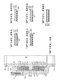
- FIG. 1 An offshore fluid transfer system employing the constant motion swivel joint illustrated in detail in Figures 2-10 is diagrammatically represented in Figure 1.
- This system comprises a submerged pipeline P extending along the ocean floor F from a subsea well or other source of petroleum or other fluid cargo (not shown) to an offshore floating buoy B that functions as a terminal both for mooring and for loading and unloading a marine tanker T.
- the buoy B is anchored in position by a plurality of chains C that extend between the buoy and a plurality of anchors A that are secured to the ocean floor F.
- the tanker T is shown secured to the buoy B by a pair of mooring lines L that permit the tanker to swing freely according to the dictates of wind and current, and yet hold the tanker a proper distance from the buoy for loading or unloading through a hose H, the hose comprising a pair of sections H1 and H2.
- a lower end of a flexible vertical hose V is connected to the horizontal pipeline P and the upper end of the hose V is connected to a swivel (not shown) in the buoy B to allow the tanker to move a full 360 degrees about the buoy B.
- a constant motion swivel joint J is connected in the hose H1, H2 between the buoy B and the tanker T.
- the constant motion swivel joint J (Fig. 2) includes an inner or male member 11 connected to a pipe or the hose section H1, and an outer or female member 12 connected to a pipe or the hose section H2.
- the lower end of the inner member 11 includes a radial flange 13 having an annular groove 17 in the outer portion of the flange.
- An axial bore 18 extends through the length of the inner member to provide a path for fluid to flow from the hose H2.
- the outer member 12 (Fig. 2) includes an enlarged upper portion 16 having an axially extending passage 19 to receive the inner member 11 in position to transfer fluid between the hoses H1 and H2, and an axial bore 23 aligned with the bore 18 of the inner member 11.
- An annular retaining flange 24 having an axial bore 25 is secured to the upper end of the outer member by a plurality of cap-screws 26 each extending through a bore 29 in the flange 24 and mounted in a threaded bore 30 in the outer member 12.
- An annular upper bushing 31 is mounted in a groove 35 in the flange 24 and is positioned between the outer surface 14 of the inner member and the retaining flanges 24.
- An annular lower bushing 36 is mounted in the groove 17 between an inner wall 20 of the outer member 12 and the flange 13.
- a plurality of annular sealing discs 41 mounted between the flanges 13 and 24 are specially designed to provide long-life fluid-tight seals between the inner and outer joint members 11, 12.
- Each of the sealing discs 41 includes an annular metal ring 42 (Fig. 4) having a low friction coating 43 bonded to one surface, and having a layer of elastomeric material 47, such as rubber, bonded to the other surface of the ring 42.
- the discs 41 are mounted (Figs. 2, 4) with the rubber coating of one disc pressed against the low-friction coating of an adjacent disc.
- An 0-ring seal 48 mounted in an annular groove 49 provides a fluid-tight seal between the retaining flange 24 and the upper end of the outer member 12.
- the amount of compression forces exerted on the sealing discs 41 can be varied by adjusting the position of the capscrews 26 relative to the bottom of the threaded bores 30. Any pressurized fluid entering a space 19a between the discs 41 and the outer member 12 or any pressurized fluid entering a space 19c between the discs 41 and the inner member 11 provides a radial compression of the rubber portion of the discs 41 resulting in an axial expansion of the rubber to provide a tight seal between the flanges 13 and 24. As the pressure of the fluid in these spaces 19a, 19c increases, the seal between the members 11, 12 becomes tighter.
- FIGs. 5, 6A, 6B employs a pair of alternately positioned sealing discs 41a, 41 b.
- the discs 41 b (Fig. 6B) includes a metal ring 42 having a pair of low friction coated surfaces 43 and the disc 41a a (Fig. 6A) includes a ring 42 having a pair of surfaces each bonded with elastomeric material 47 as discussed above.
- These discs 41a, 41b are alternately positioned, starting with one disc 41 a mounted adjacent the flange 13 and ending with another disc 41a mounted adjacent the flange 24 to prevent slippage between the flanges and the adjacent disc for small angles of rotation of the inner member relative to the outer member.
- the disc 59a (Fig. 7) includes a conical metal ring 61 having a pair of surfaces each coated with an elastomeric material 47 in the same manner as shown in Figure 6A.
- the disc 59b includes a conical metal ring 61 having a pair of low-friction coated surfaces 43 in the same manner as shown in Figure 6B.
- Approximately half of the belleville disc 59a, 59b (Fig. 7) have the radially outward edge 62 facing the retaining flange 24a and half have the radially outward edge 62 facing the radial flange 13a.
- An annular conical disc 60 having a pair of low-friction surfaces 60a, 60b, is mounted at the approximate midpoint of the stack of discs 59a, 59b and a pair of end discs 59a each having an elastomeric surface 47 on both sides, are mounted adjacent the disc 60 and another pair of end discs 59a are mounted adjacent the radial flanges 13a, 24a.
- the inclined surfaces 64, 65 of the flanges 13a, 24a press against the belleville discs 59a causing the discs 59a, 59b to center themselves about the inner member 11 a with approximately equal gaps 66, 67 between the discs and the inner and outer members 11a, 12a. This centering action prevents a rotational drag which might result if the discs press against the inner or outer member, as could happen in embodiments using flat sealing discs.
- FIG. 8A-8E Other embodiments of the sealing discs disclosed in Figures 8A-8E include features which reduce extrusion of the elastomeric material and/ or improve the sealing characteristics of the sealing discs.
- a metal ring 42 of Figure 8A is attached to a serrated elastomeric facing 47a which provides multiple sealing surfaces 52 to improve the sealing characteristics of the disc.
- An L-shaped metal ring Figure 88. reduces the amount of extrusion of the elastomeric material 47b in a radial direction when the discs are pressed tightly together, and the convoluted metal face 53 of a ring 42b of Figure 8c similarly reduces the radial extrusion of elastomeric material on an adjacent sealing disc.
- An anti- extrusion ring 54 (Fig.
- the elastomeric material of Figure 8E is reinforced with fabric to provide an elastomeric coating 58 which is resistant to extrusion.
- the inner member 11b includes a radial flange 13b positioned approximately midway between the retaining flange 24 and the lower end 19b of the axial passage 19 of the outer member 12b, and an approximately equal number of sealing discs 41 are positioned on each side of the radial flange 13b.
- An annular lower bearing 71 is mounted between the lower portion of the inner member 11 b and the outer member 12b, in addition to the bushings 31, 36 which were described in the embodiment of Figure 2.
- FIG. 10A-101 Several other embodiments of the constant motion swivel joint disclosed in Figures 10A-101 include a joint (Figs. 10A, 10B) having beveled discs between the inner and outer members and another joint (Fig. 10C) having a set of spherical discs between the inner and the outer members.
- the swivel joint disclosed in Figure 10D is similar to the embodiment shown in Figure 2 except the radial flange 13 and the lower bushing 36 shown in Figure 2 have been replaced by an annular replaceable thrust ring 77 which is threaded to the lower end of the inner member 11c.
- the swivel joint disclosed in Figure 10E includes an annular L-shaped elastomeric sealing member 78 to seal the gap between the outer surface of the inner member and the retaining flange 24 and to reduce the amount of downward pressure on the radial flange 13 when the pressure outside the swivel joint is greater than the pressure inside the swivel joint.
- the swivel joint disclosed in Figure 10F includes a retaining flange 24e and a radial flange 13e each having a low friction bearing portion 79a, 79b connected to the remainder of the flange by elastomeric rings 80a, 80b.
- the elastomeric rings 80a, 80b flex to allow small rotational movement of the inner member 11e relative to the outer member 12e without having the bearing portions 79a, 79b slide over the surface of the adjacent members 11e, 12e.
- the bearing portions 79a, 79b each slide over the surface of an adjacent member 11e, 12e in the manner of the other embodiments of Figures 2-10.
- the swivel joint J disclosed in Figure 10G includes a plurality of ball bearings 84 mounted in a raceway 85 formed in the lower end 15 of the inner member 11 and in the wall 86 of the outer member 12.
- the swivel joint disclosed in Figures 10H, 101 include a helical spring 90 and a pair of belleville washers 91 respectively to preload the sealing discs 41 by applying a force between the wall 86 of the outer member and the thrust bearing 37a, 37b.
- the force applied by spring 90 and washer 91 compensates for any wear on the sealing discs 41 and insures a fluid-tight seal between the inner and the outer members 11g, 12g and 11h, 12h.
- the present invention discloses a constant motion swivel joint having a greatly improved useful life over the prior art swivel joints without leakage of fluid from the joints.
- a plurality of sealing discs each having an elastomeric layer to absorb relatively small oscillations are mounted between an inner and outer member of the joint.
- the provision of sealing discs having a low friction coating which slides over the elastomeric layer allows for larger angles of rotation between the inner and outer members.
Landscapes
- Engineering & Computer Science (AREA)
- Mechanical Engineering (AREA)
- General Engineering & Computer Science (AREA)
- Chemical & Material Sciences (AREA)
- Combustion & Propulsion (AREA)
- Ocean & Marine Engineering (AREA)
- Joints Allowing Movement (AREA)
Claims (10)
Applications Claiming Priority (2)
| Application Number | Priority Date | Filing Date | Title |
|---|---|---|---|
| GB8010878 | 1980-04-01 | ||
| GB8010878 | 1980-04-01 |
Publications (3)
| Publication Number | Publication Date |
|---|---|
| EP0037113A2 EP0037113A2 (fr) | 1981-10-07 |
| EP0037113A3 EP0037113A3 (en) | 1982-07-28 |
| EP0037113B1 true EP0037113B1 (fr) | 1985-07-03 |
Family
ID=10512527
Family Applications (1)
| Application Number | Title | Priority Date | Filing Date |
|---|---|---|---|
| EP81102394A Expired EP0037113B1 (fr) | 1980-04-01 | 1981-03-30 | Raccord de tuyaux pivotant pour mouvement perpétuel |
Country Status (4)
| Country | Link |
|---|---|
| US (1) | US4438957A (fr) |
| EP (1) | EP0037113B1 (fr) |
| DE (1) | DE3171187D1 (fr) |
| NO (1) | NO157914C (fr) |
Families Citing this family (13)
| Publication number | Priority date | Publication date | Assignee | Title |
|---|---|---|---|---|
| FR2568343B1 (fr) * | 1984-07-24 | 1988-11-04 | Technip Geoproduction | Methode et dispositif de maintien de l'etancheite entre pieces pouvant se deplacer l'une par rapport a l'autre |
| DE69117484T2 (de) * | 1990-12-21 | 1996-08-22 | Fisher Controls Int | Graphitdichtung |
| US5354104A (en) * | 1993-01-15 | 1994-10-11 | Techlam | Flexible coupling for pipework |
| US6308994B1 (en) * | 1997-04-08 | 2001-10-30 | Swagelok Company | Fluid fitting with torque suppression arrangement |
| US6524007B1 (en) * | 1999-03-15 | 2003-02-25 | William L. Hinks | Shaft bearing-seal assembly penetrating the wall of a pressure vessel |
| US6834998B2 (en) * | 2000-03-09 | 2004-12-28 | William Lloyd Hinks | Shaft bearing-seal assembly penetrating the wall of a pressure vessel |
| US6386595B1 (en) | 2000-05-30 | 2002-05-14 | Wellstream, Inc. | Swivel joint and method for connecting conduits |
| US8025297B2 (en) * | 2002-04-10 | 2011-09-27 | The Penn State Research Foundation | Bellows with alternating layers of high and low compliance material for dynamic applications |
| FR2853042B1 (fr) * | 2003-03-26 | 2006-02-17 | Hutchinson | Flexible pour systeme de climatisation de vehicule a moteur |
| DE20316372U1 (de) * | 2003-10-23 | 2003-12-18 | Fey Lamellenringe Gmbh & Co. Kg | Flanschverbindung |
| US7182034B2 (en) * | 2004-06-04 | 2007-02-27 | Brine William H | Offshore floating dock |
| US20120280495A1 (en) * | 2011-05-06 | 2012-11-08 | Primus Green Energy Inc. | Ceramic-to-metal flange connection |
| JP6215002B2 (ja) * | 2013-10-25 | 2017-10-18 | 東京エレクトロン株式会社 | フォーカスリングの製造方法及びプラズマ処理装置の製造方法 |
Family Cites Families (13)
| Publication number | Priority date | Publication date | Assignee | Title |
|---|---|---|---|---|
| US1165876A (en) * | 1914-03-19 | 1915-12-28 | George Goodman | Pressure-indicating mechanism for pneumatic-tired vehicles. |
| US1971169A (en) * | 1931-10-29 | 1934-08-21 | Harley T Wheeler | Stuffing-box for nonrising gate valves |
| US2075019A (en) * | 1932-12-02 | 1937-03-30 | Nelson E Buck | Stop joint for electric cables |
| US3022081A (en) * | 1957-08-01 | 1962-02-20 | Victor Mfg & Gasket Co | Self-contained fluid seal |
| US2963304A (en) * | 1958-03-24 | 1960-12-06 | Youngstown Sheet And Tube Co | Swivel joint for extreme pressure and temperature ranges |
| US3316940A (en) * | 1964-06-29 | 1967-05-02 | Gratzmuller Jean Louis | Sliding seal assemblies |
| US3679235A (en) * | 1970-08-24 | 1972-07-25 | Fmc Corp | Pipe swivel joint for corrosive fluids |
| FR2251237A5 (fr) * | 1973-11-14 | 1975-06-06 | Emh | |
| US4076284A (en) * | 1976-05-05 | 1978-02-28 | Murdock Machine & Engineering Co. | Ocean floor riser connection |
| US4121861A (en) * | 1977-04-29 | 1978-10-24 | Lord Corporation | Flexible sealing joint |
| DE2808475C3 (de) * | 1978-02-28 | 1980-11-13 | Witzenmann Gmbh Metallschlauch-Fabrik Pforzheim, 7530 Pforzheim | Torsionskompensator für Rohrleitungen |
| US4236737A (en) * | 1978-09-28 | 1980-12-02 | Aeroquip Corporation | Conduit swivel joint |
| US4234197A (en) * | 1979-01-19 | 1980-11-18 | Baker International Corporation | Conduit sealing system |
-
1981
- 1981-03-12 US US06/243,169 patent/US4438957A/en not_active Expired - Lifetime
- 1981-03-30 DE DE8181102394T patent/DE3171187D1/de not_active Expired
- 1981-03-30 EP EP81102394A patent/EP0037113B1/fr not_active Expired
- 1981-03-31 NO NO811106A patent/NO157914C/no unknown
Also Published As
| Publication number | Publication date |
|---|---|
| DE3171187D1 (en) | 1985-08-08 |
| EP0037113A2 (fr) | 1981-10-07 |
| EP0037113A3 (en) | 1982-07-28 |
| NO157914B (no) | 1988-02-29 |
| NO811106L (no) | 1981-10-02 |
| NO157914C (no) | 1988-06-08 |
| US4438957A (en) | 1984-03-27 |
Similar Documents
| Publication | Publication Date | Title |
|---|---|---|
| US4561679A (en) | Seal pressure reduction system | |
| EP0037113B1 (fr) | Raccord de tuyaux pivotant pour mouvement perpétuel | |
| CA1222785A (fr) | Garnitures etanches pour raccord a rotule sur reseau fluidique | |
| US9845879B2 (en) | High pressure dynamic sealing arrangement | |
| US4626003A (en) | Constant motion swivel seal assembly | |
| CA1200571A (fr) | Articulation a rotule | |
| US4819966A (en) | Sealing means for a multipath, multipass swivel | |
| JPS6252292A (ja) | 流動装置 | |
| GB2168939A (en) | Single point mooring system swivel assembly | |
| US3088759A (en) | Swivel pipe coupling having low friction seals | |
| EP3460170B1 (fr) | Système de joint à face axiale | |
| EP0084877B1 (fr) | Joint de dilatation | |
| US4781404A (en) | Multi-path fluid swivel | |
| AU697282B2 (en) | Sealing arrangement | |
| US4337970A (en) | Universal joint for multiple conduit system | |
| US4311327A (en) | Universal joint for multiple flowline system | |
| GB2132297A (en) | Pipe swivel joint | |
| US10100962B2 (en) | High pressure fluid swivel | |
| EP1502051B1 (fr) | Raccordement de tuyaux permettant un deplacement relatif et comprenant un dispositif de precontrainte assurant un espace d'etancheite | |
| AU599378B2 (en) | Multi-path fluid swivel | |
| Herbert et al. | A High-Pressure Swivel for Natural Gas Service and Oscillating Motion in a Marine Environment | |
| Ortloff | Swivels for Production Risers and Offshore Terminals |
Legal Events
| Date | Code | Title | Description |
|---|---|---|---|
| PUAI | Public reference made under article 153(3) epc to a published international application that has entered the european phase |
Free format text: ORIGINAL CODE: 0009012 |
|
| AK | Designated contracting states |
Designated state(s): DE FR GB IT |
|
| PUAL | Search report despatched |
Free format text: ORIGINAL CODE: 0009013 |
|
| 17P | Request for examination filed |
Effective date: 19820329 |
|
| AK | Designated contracting states |
Designated state(s): DE FR GB IT |
|
| ITF | It: translation for a ep patent filed | ||
| GRAA | (expected) grant |
Free format text: ORIGINAL CODE: 0009210 |
|
| AK | Designated contracting states |
Designated state(s): DE FR GB IT |
|
| REF | Corresponds to: |
Ref document number: 3171187 Country of ref document: DE Date of ref document: 19850808 |
|
| ET | Fr: translation filed | ||
| PLBE | No opposition filed within time limit |
Free format text: ORIGINAL CODE: 0009261 |
|
| STAA | Information on the status of an ep patent application or granted ep patent |
Free format text: STATUS: NO OPPOSITION FILED WITHIN TIME LIMIT |
|
| 26N | No opposition filed | ||
| PGFP | Annual fee paid to national office [announced via postgrant information from national office to epo] |
Ref country code: DE Payment date: 19890316 Year of fee payment: 9 |
|
| PGFP | Annual fee paid to national office [announced via postgrant information from national office to epo] |
Ref country code: FR Payment date: 19890317 Year of fee payment: 9 |
|
| ITTA | It: last paid annual fee | ||
| PGFP | Annual fee paid to national office [announced via postgrant information from national office to epo] |
Ref country code: GB Payment date: 19890331 Year of fee payment: 9 |
|
| PG25 | Lapsed in a contracting state [announced via postgrant information from national office to epo] |
Ref country code: GB Effective date: 19900330 |
|
| GBPC | Gb: european patent ceased through non-payment of renewal fee | ||
| PG25 | Lapsed in a contracting state [announced via postgrant information from national office to epo] |
Ref country code: FR Effective date: 19901130 |
|
| PG25 | Lapsed in a contracting state [announced via postgrant information from national office to epo] |
Ref country code: DE Effective date: 19901201 |
|
| REG | Reference to a national code |
Ref country code: FR Ref legal event code: ST |