EP0037147B1 - Dispositif d'alimentation pour moissonneuse de récoltes - Google Patents
Dispositif d'alimentation pour moissonneuse de récoltes Download PDFInfo
- Publication number
- EP0037147B1 EP0037147B1 EP81200324A EP81200324A EP0037147B1 EP 0037147 B1 EP0037147 B1 EP 0037147B1 EP 81200324 A EP81200324 A EP 81200324A EP 81200324 A EP81200324 A EP 81200324A EP 0037147 B1 EP0037147 B1 EP 0037147B1
- Authority
- EP
- European Patent Office
- Prior art keywords
- floor
- feeder
- feeder housing
- crop material
- frangible
- Prior art date
- Legal status (The legal status is an assumption and is not a legal conclusion. Google has not performed a legal analysis and makes no representation as to the accuracy of the status listed.)
- Expired
Links
Images
Classifications
-
- A—HUMAN NECESSITIES
- A01—AGRICULTURE; FORESTRY; ANIMAL HUSBANDRY; HUNTING; TRAPPING; FISHING
- A01F—PROCESSING OF HARVESTED PRODUCE; HAY OR STRAW PRESSES; DEVICES FOR STORING AGRICULTURAL OR HORTICULTURAL PRODUCE
- A01F12/00—Parts or details of threshing apparatus
- A01F12/10—Feeders
- A01F12/16—Safety devices
-
- Y—GENERAL TAGGING OF NEW TECHNOLOGICAL DEVELOPMENTS; GENERAL TAGGING OF CROSS-SECTIONAL TECHNOLOGIES SPANNING OVER SEVERAL SECTIONS OF THE IPC; TECHNICAL SUBJECTS COVERED BY FORMER USPC CROSS-REFERENCE ART COLLECTIONS [XRACs] AND DIGESTS
- Y10—TECHNICAL SUBJECTS COVERED BY FORMER USPC
- Y10S—TECHNICAL SUBJECTS COVERED BY FORMER USPC CROSS-REFERENCE ART COLLECTIONS [XRACs] AND DIGESTS
- Y10S209/00—Classifying, separating, and assorting solids
- Y10S209/935—Ambulant
Definitions
- This invention relates generally to crop harvesting machines such as threshing machines, more commonly known as combines. More particularly the invention concerns the feeder attached to the front of the base unit of such a machine which is used to transfer the crop material from the harvesting attachment or header upwards into the base unit where the processing operation such as the threshing operation occurs. Specifically, the invention is concerned with the shape of the floor of the feeder housing and the cooperative effect of this shape with the location of a stone ejecting trap door that is effective to eject stones and other non-frangible objects from the crop material as they are passed along with the crop material from the header upwardly through the feeder housing towards the base unit.
- stone traps were routinely provided to separate out large hard objects or stones that generally were greater than seven or ten centimeters (three or four inches) in size.
- the stone traps provided in the conventional combines were utilized generally in two types of stone ejecting systems.
- the passive type of stone ejecting system employed a stone trap with a space or gap between the top of the crop elevator or conveyor within the feeder housing and the base unit threshing apparatus (US 3,664,348).
- hard objects or stones were conveyed upwardly along with the crop material from the header through the feeder housing towards the threshing apparatus. When the crop material passed over the gap, stones, by their very weight, would fall down through the gap into the stone trap.
- the second type of stone ejecting system generally employed an active system which utilized some sort of an electronic sensor, such as an acoustic transducer typically in the form of a piezoelectric disc mounted in a sensing plate, in conjunction with a stone trap (US 3,675,660).
- the electronic sensor responded to the characteristics of the sound, such as the amplitude and frequency, that an impacting stone generated in the sensing plate. This signal would then be transferred through an electronic circuit that filtered out the range within which the amplitude and frequency was characteristic of stones. Within this characteristic spectral range the electronic circuit automatically activated a latch releasing mechanism on a door along the bottom of the feeder housing that would pivot open to permit the stones or hard objects to be ejected from the feeder housing along with a small amount of crop material.
- An alternate type of active stone ejecting system utilized a pinch roll rotatably mounted in the feeder housing at a predetermined distance above the trap door (US 3,971,390).
- a pinch roll rotatably mounted in the feeder housing at a predetermined distance above the trap door (US 3,971,390).
- a stone or other non-frangible object passing through an axial flow or other rotary type of combine is more apt to damage the entire length of the concaves, which with their rasp or rub bars cooperate with the rotors to thresh the crop material.
- a stone passing through a conventional type of combine with a transversely oriented threshing cylinder and underlying concave contacts only a very small portion of the concave and is therefore likely to cause relatively little damage in its single pass about a portion of the cylinder.
- an improved detecting system such as that shown and described in the aforementioned copending US patent application, used on an axial flow or other rotary type of combine necessitates a much higher percentage of stone ejection.
- Any improved ejecting system operating within this new detection system must be fast acting since the crop material has been determined to move at an approximate rate of 4, 5 m (fifteen feet) per second through a typical feeder housing and the typical reaction time from time of detection of a stone or hard object to ejection is 0.2 of a second.
- a feeder for a harvesting machine comprising a feeder housing with an inlet, an opposing outlet and a generally elongate floor; conveying means in the feeder housing for conveying crop material along the floor from the inlet to the outlet and object ejecting means, part of which forms part of the floor, between the inlet and the outlet, selectively actuable upon entry of a non-frangible object with the crop material into the feeder housing to create an opening in the floor between the inlet and the outlet such that crop material and the non-frangible object are carried out of the feeder housing;
- the feeder being characterized by the generally elongate floor comprising a first portion and a second portion situated after and obliquely angled upwards to the first portion; the conveying means being disposed to convey crop material, in a first direction, across the first portion of the floor and, in a second direction oblique to the first direction, across the second portion of the floor when the object ejecting means are in the non-actuated position and the-object
- the improved feeder design according to the present invention is compatible with an electronic stone detection system which will reliably detect and subsequently eject stones and other non-frangible objects.
- the improved feeder utilizes a trap door at the point where, under normal operating conditions, the direction of the flow path of the crop material is changed; the arrangement being such that the trap door may be opened and the existing flow or transport velocity of the crop material as it moves upwardly through the feeder housing along its initial vectorial direction of travel, is utilized to carry stones and other hard objects out the trap door prior to their reaching the threshing apparatus.
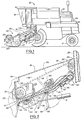
- a combine in side elevational view with the critical portions of this invention illustrated in fragmentary manner by having their outline shown in relative detail.
- the combine 10 has a mobile frame supported by a pair of primary driving wheels 11 in the front and a smaller pair of steerable wheels 12 in the rear.
- the combine 10 is powered by an engine (not shown) mounted beneath the engine housing 14 and on the upper portion of the combine in a suitable fashion and by means of belts or sprocket driven chains connectable to the operational components of the combine.
- the combine 10 has a main frame or housing 15 that internally supports the threshing and separating apparatus, as well as the cleaning means, both of which are not shown.
- the operators cab 16 extends forwardly out over the front of the main frame 15 atop the feeder housing.
- the rear housing 19 encloses further components such as a discharge beater and grate assembly (not shown).
- the grain tank 20 is mounted essentially atop the combine 10 and an unloading auger 21 is operably connected thereto and extends along the side of the combine in its inboard transport position.
- the feeder housing 18 has detachably mounted to its front a header attachment, indicated generally by the numeral 22.
- the header attachment may either be of the type that is a row crop corn harvesting attachment, a windrow pick up attachment, a grain-bat reel type or a soybean reel type of attachment.
- the header 22 as shown in Fig. 1 is a soybean type header and in this instance comprises a tined reel 23 that is adjustably and rotatably mounted to the header 22 across substantially its entire transverse width. Beneath the reel 23 is a direct-cut sickle bar 24 which serves to cut the crop material as the combine 10 moves across the field.
- the reel 23 carries the crop material back to the consolidating auger 25, which consolidates the cut crop material and transfers it rearwardly and upwardly through a suitable opening into the front of the feeder housing 18.
- the feeder housing 18 has rotatably mounted within a plurality of chains 41 interconnected by slats 42 which are rotatably driven to convey the crop material upwardly to the threshing and separating mechanism (not shown) of the combine 10.
- This slat and chain apparatus is generally known as crop elevator 26.
- the feeder housing 18 is movably affixed to the main frame 15 of the combine via a vertical support beam 28 and a support plate 29 on each side of the combine.
- the housing 18 is hinged for pivotable movement about mounting 30.
- the feeder housing 18 is raised and lowered by means of a pair of hydraulic cylinders 31, only one of which is shown and which are fastened to the base unit of the combine 10 on one end and appropriately fastened for up and down movement by coupling 32 to mounting plate 34.
- the feeder housing 18 has a forward portion 35 that has an opening between the side sheets 36, only one of which is shown, and to which is suitably attached the appropriate header 22.
- the crop elevator 26 is entrained about a driven front guide roller 38 and a driving rear roller 39.
- the driving rear roller 39 has its shaft serve as an integral part of the mounting 30 and is the axis about which the feeder housing 18 is rotated when the header and feeder housing 18 are raised or lowered.
- a pinch roll 40 is mounted transversely across the feeder housing 18 intermediately of the driven front guide roll 38 and the rear driving guide roll 39.
- the crop elevator 26 is normally comprised of three spaced apart chains 41, only one of which is shown, interconnected by a plurality of U-shaped slats 42.
- the two outside chains 41 pass generally about sprockets on the opposing ends of the shafts which pass through the driven front guide roll 38 and the rear driving guide roll 39.
- the crop elevator 26 is driven generally in a counterclockwise direction (as seen in the figures 1, 2) and carries the crop material from the header upwardly and rearwardly along its predetermined path toward the threshing and separating apparatus, not shown, in the base unit of the combine 10.
- the floor of the feeder housing 18 is comprised of two major portions with four distinct sections. Across the front of the feeder housing 18 there is a sensing plate or bar 44 which spans its entire width. This sensing bar 44 is mounted so as to be acoustically isolated from any vibrations or noise induced by the feeder housing 18 during the operation of the combine 10. This acoustical isolation is achieved by means of non-magnetic sound supressive material 45, such as rubber, which is plated between the front and rear edges of the sensing bar and the feeder housing mounting brackets.
- the sensing bar 44 is shown in greater detail in the aforementioned copending U.S.-A-4275546.
- the second section of the feeder housing 18 comprises a section 46 that is in the same flow plane as the upper surface of the sensing bar 44.
- a pivotally mounted trap door is positioned and designed so that the crop material initially follows the flow path defined by the top portion of sensing bar 44 and the second section 46 of the feeder housing 18.
- the door is angled upwardly in a generally oblique direction from the direction of travel of the crop material defined by the first portion of the feeder housing.
- This upwardly or obliquely inclined portion of the trap door 48 defines the path which the crop material will follow as it is conveyed by the crop elevator 26 upwardly from the second section 46 of the feeder housing 18 into the threshing and separating apparatus of the combine.
- the last portion of the feeder housing floor comprises a section 50 which continues in the upwardly extending direction along the same general axis as that established by the obliquely angled portion 49 of the trap door 48.
- the floor of the feeder housing 18 establishes and defines a flow path for the crop material in conjunction with the crop elevator 26 which serves to convey the crop material from the header upwardly into the threshing and separating apparatus of the combine 10.
- the trap door 48 is hingedly mounted at location 51 to the underside of section 46.
- the opposing end of trap door 48 has a latching tab 52 affixed to its underside. Tab 52 cooperates with the latching means 54 to hold the trap door 48 in the closed position during operation.
- the electronic stone detecting circuitry indicated generally by the numeral 55, connects the sensing bar 44 with the latching means 54.
- the latching means 54 has a retractable plunger 56 which is retracted upon sensing the impact of the stone or other non-frangible object upon the sensing plate 44 by the stone detecting circuitry 55.
- the stone detecting circuitry 55 When the stone detecting circuitry 55 has been activated and the trap door 48 has dropped to the open position, the door may be returned to its closed position manually by engaging a handle 58 and pivoting it and the door 48 upwardly to its closed position.
- the combine 10 is driven across the field of crop material which is harvested by the harvesting attachment or header 22.
- the header consolidates the crop material via the consolidating auger 25 and transfers the crop material rearwardly and upwardly into the feeder housing 18.
- the feeder housing 18 has its crop elevator 26, rotatably moving in a generally counterclockwise direction (as seen in the Figures 1, 2) to engage the crop material with the slats 42 and chains 41 to move the crop material generally rearwardly and upwardly towards the threshing and separating apparatus of the combine 10.
- the sensing bar 44 Any rocks or non-frangible objects must necessarily strike the sensing bar 44.
- the stone detecting circuitry 55 Upon impact the spectral characteristics of the impacting object are analyzed by the stone detecting circuitry 55 by having the amplitude and frequency of the sensing bar 44 transmitted thereto.
- the circuitry 55 sends a signal to the latching means 54. This signal causes the plunger 56 to retract out of retaining interference with locking tab 52. This releases the trap door 48 from its raised position and permits the door to swing open either by force of gravity on its own or by some spring assisted or otherwise mechanically assisted drive.
- the undesired non-frangible object or stone is ejected safely from the combine 10 without being ingested into the threshing and separating apparatus, thereby avoiding considerable damage to the threshing and separating apparatus of the combine.
- the crop material and non-frangible objects are assisted in retaining their original direction of travel along the first portion of the predetermined path of travel by the action of the pinch roll 40 which insures that the chains 41 and their interconnecting slats 42 at the point of discontinuity in the floor engage and retain the crop material in its flow along the first portion of the predetermined path.
- the operator When the operator is satisfied that the stone or other non-frangible object has been safely removed from the combine, he may manually engage the closing handle 58 and raise the trap door from its generally downward position to its fully raised position.
- the pinch roll 40 could be operable connected to the trap door 48 so that upon actuation of the latch means 54 by the stone detecting circuitry 55 the pinch roll also is lowered simultaneously with the opening of the trap door 48 to block the path of flow of the crop material upwardly and ensure that all of the crop material and the accompanying stones or non-frangible objects are directed out of the opening in the floor of the feeder housing 18 by the opening of the trap door 48.
Landscapes
- Life Sciences & Earth Sciences (AREA)
- Environmental Sciences (AREA)
- Harvester Elements (AREA)
- Threshing Machine Elements (AREA)
Claims (8)
Applications Claiming Priority (2)
| Application Number | Priority Date | Filing Date | Title |
|---|---|---|---|
| US06/134,722 US4305244A (en) | 1980-03-27 | 1980-03-27 | Feeder house design for a combine |
| US134722 | 1980-03-27 |
Publications (2)
| Publication Number | Publication Date |
|---|---|
| EP0037147A1 EP0037147A1 (fr) | 1981-10-07 |
| EP0037147B1 true EP0037147B1 (fr) | 1983-09-07 |
Family
ID=22464681
Family Applications (1)
| Application Number | Title | Priority Date | Filing Date |
|---|---|---|---|
| EP81200324A Expired EP0037147B1 (fr) | 1980-03-27 | 1981-03-24 | Dispositif d'alimentation pour moissonneuse de récoltes |
Country Status (4)
| Country | Link |
|---|---|
| US (1) | US4305244A (fr) |
| EP (1) | EP0037147B1 (fr) |
| CA (1) | CA1140020A (fr) |
| DE (1) | DE3160836D1 (fr) |
Families Citing this family (12)
| Publication number | Priority date | Publication date | Assignee | Title |
|---|---|---|---|---|
| US4294062A (en) * | 1980-03-27 | 1981-10-13 | Sperry Corporation | Sensing bar |
| DE19730701A1 (de) * | 1997-07-17 | 1999-01-21 | Claas Selbstfahr Erntemasch | Förderkanal für halmförmiges Erntegut |
| US6116008A (en) * | 1999-04-01 | 2000-09-12 | New Holland North America, Inc. | Pivoting faceplate for a feederhouse on an agricultural combine |
| DE60003604T2 (de) | 1999-04-12 | 2004-02-12 | Cnh Belgium N.V. | Detektion und Auswurf von Steinen für Schrägfördergehäuse eines Mähdreschers |
| US20060277883A1 (en) * | 2005-06-10 | 2006-12-14 | Berger John G | Acoustic stone detection for a feederhouse on an agricultural combine |
| US7207165B2 (en) * | 2005-07-22 | 2007-04-24 | Cnh America Llc | Non-frangible object detection method and apparatus for use with harvester |
| CA2572274C (fr) * | 2006-12-29 | 2014-05-27 | Honey Bee Manufacturing Ltd. | Recepteur de roches pour bec cueilleur de moissonneuse-batteuse |
| US7993187B2 (en) * | 2007-05-23 | 2011-08-09 | Cnh America Llc | Foreign object detection and removal system for a combine harvester |
| US9219955B2 (en) * | 2011-01-14 | 2015-12-22 | Incube Labs, Llc | Apparatus, system and method for underwater voice communication by a diver |
| WO2012112811A2 (fr) | 2011-02-18 | 2012-08-23 | Incube Labs, Llc | Appareil, système et procédé pour la signalisation sous-marine de messages audio à un plongeur |
| US9642309B2 (en) | 2013-03-15 | 2017-05-09 | Oxbo International Corporation | Yield monitoring system |
| BR102014010216B1 (pt) * | 2014-04-28 | 2020-05-05 | Marchesan Implementos E Maqu Agricolas Tatu S A | esteira alimentadora para uma colheitadeira de cana-de-açúcar |
Citations (5)
| Publication number | Priority date | Publication date | Assignee | Title |
|---|---|---|---|---|
| US2528232A (en) * | 1945-04-28 | 1950-10-31 | Case Co J I | Feed plate for combines |
| US2959175A (en) * | 1958-03-26 | 1960-11-08 | Allis Chalmers Mfg Co | Mounting for a threshing cylinder concave |
| US3675660A (en) * | 1971-05-03 | 1972-07-11 | Massey Ferguson Ind Ltd | Combine stone trap door |
| FR2205263A1 (fr) * | 1972-11-08 | 1974-05-31 | Massey Ferguson Ind Ltd | |
| FR2272590A1 (fr) * | 1974-06-03 | 1975-12-26 | Sperry Rand Corp |
Family Cites Families (2)
| Publication number | Priority date | Publication date | Assignee | Title |
|---|---|---|---|---|
| US2657799A (en) * | 1949-06-09 | 1953-11-03 | Odin Corp | Can sorting machine |
| CA906866A (en) * | 1970-03-13 | 1972-08-08 | White Motor Corporation Of Canada Limited | Stone trap for a combine |
-
1980
- 1980-03-27 US US06/134,722 patent/US4305244A/en not_active Expired - Lifetime
-
1981
- 1981-01-30 CA CA000369713A patent/CA1140020A/fr not_active Expired
- 1981-03-24 EP EP81200324A patent/EP0037147B1/fr not_active Expired
- 1981-03-24 DE DE8181200324T patent/DE3160836D1/de not_active Expired
Patent Citations (5)
| Publication number | Priority date | Publication date | Assignee | Title |
|---|---|---|---|---|
| US2528232A (en) * | 1945-04-28 | 1950-10-31 | Case Co J I | Feed plate for combines |
| US2959175A (en) * | 1958-03-26 | 1960-11-08 | Allis Chalmers Mfg Co | Mounting for a threshing cylinder concave |
| US3675660A (en) * | 1971-05-03 | 1972-07-11 | Massey Ferguson Ind Ltd | Combine stone trap door |
| FR2205263A1 (fr) * | 1972-11-08 | 1974-05-31 | Massey Ferguson Ind Ltd | |
| FR2272590A1 (fr) * | 1974-06-03 | 1975-12-26 | Sperry Rand Corp |
Also Published As
| Publication number | Publication date |
|---|---|
| EP0037147A1 (fr) | 1981-10-07 |
| US4305244A (en) | 1981-12-15 |
| DE3160836D1 (en) | 1983-10-13 |
| CA1140020A (fr) | 1983-01-25 |
Similar Documents
| Publication | Publication Date | Title |
|---|---|---|
| US4294062A (en) | Sensing bar | |
| EP0037147B1 (fr) | Dispositif d'alimentation pour moissonneuse de récoltes | |
| US6298641B1 (en) | Stone ejection for a feederhouse on an agriculture combine | |
| US3805798A (en) | Combine harvester protection system | |
| US3675660A (en) | Combine stone trap door | |
| US4322933A (en) | Stone trapdoor trip mechanism | |
| US4343137A (en) | Crop elevator decelerating means | |
| US6430904B1 (en) | Platform auger torque sensing brake activation | |
| US7993187B2 (en) | Foreign object detection and removal system for a combine harvester | |
| GB2068549A (en) | Protective apparatus for agricultural machinery | |
| EP0152085B1 (fr) | Presse à balles rondes | |
| EP1745690B1 (fr) | Méthode et dispositif de détection d'objets durs pour utilisation dans une moissonneuse | |
| GB2185871A (en) | A stone trap for a combine harvester | |
| EP3238528B1 (fr) | Capteur de résidus optiques dans un logement de résidus à triple souffleur | |
| US20130310120A1 (en) | Intake feeder system for a combine harvester | |
| US4540003A (en) | Offset grain loss sensor for combine harvesters | |
| US3994304A (en) | Back-flow retarding feed plate for rotary combine | |
| US4288969A (en) | Stone trap seal | |
| US7337603B2 (en) | Round baler leaf reclamation device | |
| US20060277883A1 (en) | Acoustic stone detection for a feederhouse on an agricultural combine | |
| US4542617A (en) | Baling machine | |
| US4768525A (en) | Stone ejection door mechanism for harvesting equipment | |
| EP4413849A1 (fr) | Système de détection de palette rompue pour elevateur de moissonneuse-batteuse | |
| EP1731019B1 (fr) | Détection acoustique de pierres pour convoyeur d'une moissonneuse-batteuse | |
| JP2000032833A (ja) | 脱穀装置における排藁詰まり検出装置 |
Legal Events
| Date | Code | Title | Description |
|---|---|---|---|
| PUAI | Public reference made under article 153(3) epc to a published international application that has entered the european phase |
Free format text: ORIGINAL CODE: 0009012 |
|
| AK | Designated contracting states |
Designated state(s): DE FR GB |
|
| 17P | Request for examination filed |
Effective date: 19820312 |
|
| GRAA | (expected) grant |
Free format text: ORIGINAL CODE: 0009210 |
|
| AK | Designated contracting states |
Designated state(s): DE FR GB |
|
| REF | Corresponds to: |
Ref document number: 3160836 Country of ref document: DE Date of ref document: 19831013 |
|
| ET | Fr: translation filed | ||
| PLBE | No opposition filed within time limit |
Free format text: ORIGINAL CODE: 0009261 |
|
| STAA | Information on the status of an ep patent application or granted ep patent |
Free format text: STATUS: NO OPPOSITION FILED WITHIN TIME LIMIT |
|
| 26N | No opposition filed | ||
| PGFP | Annual fee paid to national office [announced via postgrant information from national office to epo] |
Ref country code: DE Payment date: 19991223 Year of fee payment: 20 |
|
| PGFP | Annual fee paid to national office [announced via postgrant information from national office to epo] |
Ref country code: GB Payment date: 19991224 Year of fee payment: 20 |
|
| PGFP | Annual fee paid to national office [announced via postgrant information from national office to epo] |
Ref country code: FR Payment date: 20000120 Year of fee payment: 20 |
|
| PG25 | Lapsed in a contracting state [announced via postgrant information from national office to epo] |
Ref country code: GB Free format text: LAPSE BECAUSE OF EXPIRATION OF PROTECTION Effective date: 20010323 |
|
| REG | Reference to a national code |
Ref country code: GB Ref legal event code: PE20 Effective date: 20010323 |