EP0037155B1 - Presse à balles cylindriques - Google Patents
Presse à balles cylindriques Download PDFInfo
- Publication number
- EP0037155B1 EP0037155B1 EP81200340A EP81200340A EP0037155B1 EP 0037155 B1 EP0037155 B1 EP 0037155B1 EP 81200340 A EP81200340 A EP 81200340A EP 81200340 A EP81200340 A EP 81200340A EP 0037155 B1 EP0037155 B1 EP 0037155B1
- Authority
- EP
- European Patent Office
- Prior art keywords
- rollers
- bale
- shifting
- baler
- roller
- Prior art date
- Legal status (The legal status is an assumption and is not a legal conclusion. Google has not performed a legal analysis and makes no representation as to the accuracy of the status listed.)
- Expired
Links
Images
Classifications
-
- A—HUMAN NECESSITIES
- A01—AGRICULTURE; FORESTRY; ANIMAL HUSBANDRY; HUNTING; TRAPPING; FISHING
- A01F—PROCESSING OF HARVESTED PRODUCE; HAY OR STRAW PRESSES; DEVICES FOR STORING AGRICULTURAL OR HORTICULTURAL PRODUCE
- A01F15/00—Baling presses for straw, hay or the like
- A01F15/08—Details
- A01F15/0875—Discharge devices
- A01F15/0883—Discharge devices for round balers
-
- A—HUMAN NECESSITIES
- A01—AGRICULTURE; FORESTRY; ANIMAL HUSBANDRY; HUNTING; TRAPPING; FISHING
- A01F—PROCESSING OF HARVESTED PRODUCE; HAY OR STRAW PRESSES; DEVICES FOR STORING AGRICULTURAL OR HORTICULTURAL PRODUCE
- A01F15/00—Baling presses for straw, hay or the like
- A01F15/07—Rotobalers, i.e. machines for forming cylindrical bales by winding and pressing
-
- A—HUMAN NECESSITIES
- A01—AGRICULTURE; FORESTRY; ANIMAL HUSBANDRY; HUNTING; TRAPPING; FISHING
- A01F—PROCESSING OF HARVESTED PRODUCE; HAY OR STRAW PRESSES; DEVICES FOR STORING AGRICULTURAL OR HORTICULTURAL PRODUCE
- A01F15/00—Baling presses for straw, hay or the like
- A01F15/07—Rotobalers, i.e. machines for forming cylindrical bales by winding and pressing
- A01F2015/079—Sledge for rollers of the pressing chamber
-
- A—HUMAN NECESSITIES
- A01—AGRICULTURE; FORESTRY; ANIMAL HUSBANDRY; HUNTING; TRAPPING; FISHING
- A01F—PROCESSING OF HARVESTED PRODUCE; HAY OR STRAW PRESSES; DEVICES FOR STORING AGRICULTURAL OR HORTICULTURAL PRODUCE
- A01F15/00—Baling presses for straw, hay or the like
- A01F15/07—Rotobalers, i.e. machines for forming cylindrical bales by winding and pressing
- A01F2015/0795—Pressing chamber with variable volume
Definitions
- This invention relates generally to balers for forming cylindrical bales, such as balers used for baling agricultural crop material and more commonly known as Round Balers.
- balers There are numerous roll-bale forming machines, or round balers, both in the patent art and in the market place, and they use a variety of apparatus.
- Most systems to form the bale include a chamber with a hinged upper frame which operates in a clamshell type fashion to unload the finished bale and some system within the chamber to furnish cylindrical motion to the crop.
- motive systems tend to exist in two classes.
- One type has an expanding cavity in which the motive means begins in a configuration which forms a small bale, maintains compression upon it, and gradually expands to permit the bale to grow to full size.
- the cylindrical motion is typically imparted to the bale in these devices by a continuous belt or chain system, which permits expansion of the chamber by releasing tension on an idler on the belt or chain as it moves in the return path not in contact with the bale (US-A-3.827.223 and US-A-4.159.615).
- the other type of baler has a fixed chamber size with motive means located at the periphery of the chamber. In such a system the bale builds up without outside compression until it reaches its maximum size and then the compression begins. This type system forms a bale relatively loosely packed throughout its interior with a tightly wound outside "shell".
- the fixed chamber balers use multiple short length belts (US-A-4.119.026) or large metal rollers (DE-A-26.02.231 and 26.58.210) at the outside limits of the chamber to yield the cylindrical motion. While the rollers, particularly, have the advantage of low maintenance requirements and unlimited life, the bale formed by the fixed cavity is less desirable, since in any process of use, once the outer layers are removed the bale loses its configuration and self-supporting characteristic.
- a baler for forming cylindrical bales comprising a plurality of rotating rollers generally enclosing a bale forming region and operable to impart motion to baleable material as it is fed into the bale forming region to form a bale of cylindrical shape, means permitting shifting of a set of rollers positioned inwardly of a further set of stationary rollers and movable outwardly in expansion paths to a position generally between the stationary rollers so that a position is reached circumferentially adjacent to the stationary rollers at the prescribed outer limits of the bale as the final size of the bale is obtained and means for restraining the shifting rollers in their expansion paths to create compressive force on the bale so formed.
- rollers are driven by conventional drive means such as one continuous chain for each half of the clamshell chamber, or individual small chain drives progressing around the chamber from roller to roller.
- rollers of the shifting set are each driven individually by a chain coupling from each shifting roller to the stationary position roller to which it is adjacent.
- the shifting rollers are restrained by springs into a position fully radially inward from the stationary rollers.
- each shifting roller orbits around its adjacent stationary roller.
- the drive system for the moveable roller can be a simple chain drive from the fixed roller.
- an idler system can be used to adjust for stretch in the chain.
- the shifting rollers are pulled into their innermost position by spring action and pushed out to their outermost positions by the growth of the bale.
- Spring tension settings thus determine the compression of the forming bale.
- the spring tension can then be controlled to regulate the density of the inner portion of the resulting round bale.
- a round baler is thus obtained which combines aspects of the type of balers with an expanding bale forming cavity with other aspects of the type of balers with a fixed bale forming chamber.
- the baler according to the invention uses the low maintenance rollers such as known from balers with a fixed bale forming chamber and nevertheless is operable to compress the bale formed therein throughout the greater part of its formation.
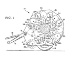
- Fig. 1 The preferred embodiment of the invention is shown in Fig. 1 in a simplified cutaway view showing part of the structure within a round baler.
- Round baler 10 is mounted upon frame 12 which rides upon wheels 14 and is pulled behind a tractor (not shown) by means of a hitch bar 16.
- Pick-up system 20 is arranged to engage, raise and feed a swath or windrow of crop material which is conveyed by tine pick-up fingers 22 and fed into contact with the rollers of baler 10.
- Shifting rollers 26 through 38 are all spring loaded into the initial closely grouped positions shown in Fig. 1 to begin compression of the bale when it reaches the size of the core 40 of bale 42.
- each shifting roller moves around its adjacent stationary roller.
- Stationary rollers 24 and 48 through 58 are located at a radius of expanded grouping to permit growth of the bale to the maximum size as shown by bale 42.
- each shifting roller gradually is forced outward until, at the bale size 42, the shifting rollers occupy the spaces between the stationary rollers and continue to aid in compressing and rotating the bale 42.
- Each shifting roller is also pictured in its outermost position in a phantom view generally on the same circle of the centers with the stationary rollers.
- the shifting rollers 26 through 38 move in circular orbits around their associated stationary rollers as the core 40 grows to the size of the bale 42.
- the guide slot 44, built into the side sheets (not shown) of frame 12 shows a typical arrangement for restraining the movement of the shifting roller 28 and maintaining the desired circular orbit as the shifting roller 28 moves to the position 28A with the expansion of the bale 42.
- Shifting rollers 30 through 38 are similarly restrained as they move through their individual orbits.
- the shifting roller 26 is required to follow a somewhat different path because of its unique location near the pick-up system 20, and due to the fact that it is in close proximity to the first roller 24.
- the shifting roller 26 therefore indeed has a shortened path to permit its cooperation with the pick-up system.
- the roller 26 is only required to shift a relatively short distance, but its path is, nevertheless, a circular orbit around roller 24.
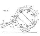
- Fig. 2 is a simplified side view of the preferred embodiment of the invention showing only the stationary rollers and the drive system for rotating them.
- Frame 12 of roll baler 10 is constructed with a hinged upper frame portion 60 which operates in the aforementioned clamshell fashion to permit unloading of the completed bale 42.
- This unloading process involves the rear portion or tailgate 60, of frame 12 lifting up to expose the bale and permit pushing the bale rearward out of the baler.
- FIG. 2 The drive system of the preferred embodiment is shown in Fig. 2 where the gear box 19, driven from the drive shaft 18, drives the stationary rollers of both the front portion and the tailgate 60 of the frame 12 independently.
- the front stationary rollers 58, 48 and 24 are driven from the gear box 19 by a chain 62 which passes from the gear box 19 to a sprocket 64 on the roller 58, a sprocket 66 on the roller 48, a sprocket 68 on the roller 24, around a tensioning idler 46, and back to the gear box 19.
- the stationary rollers of the tailgate 60 are driven from the gear box 19 by means of a separate drive chain 70 passing from the gear box 19 to a sprocket 72 of the roller 56. Alternately they can be driven from the roller 58 by using an additional sprocket coaxially with the sprocket 64 driving a shorter length of chain to sprocket 72.
- Roller 56 is located at the pivot point of the tailgate 60 and, therefore, is the initial drive point for all of the rollers within the tailgate 60. As the tailgate 60 lifts or lowers no change occurs in the length of its drive chain path.
- Drive chain 74 progresses from sprocket 72 on roller 56 to and around the sprockets 76, 78 and 80 on the rollers 54, 52 and 50, respectively, and then back to sprocket 72. Since the drive sprocket 72 is located at the pivot point of the tailgate 60, the orientation of said tailgate 60 has no effect on the drive chain 74.
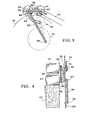
- Fig. 3 a schematic representation of a single pair of rollers, shows the means for powering and controlling the typical shifting roller 34 around the stationary roller 54.
- This set of rollers is typical of all the sets, since each shifting roller of the preferred embodiment is driven from its associated stationary roller, whether the set is located within the front portion of the baler or within the tailgate 60.
- the stationary roller 54 rotating on shaft 82, is powered by the chain 74 driving sprocket 84.
- the stationary roller 54 drives the shifting roller 34 by means of sprocket 84 driving a chain 86 which in turn drives a sprocket 88 on the roller 34.
- a spring 90 normally forces the roller 34 into a position 92 from which it is pushed outward as the core 40 grows to the bale 42.
- a guide slot 94, a restraining shaft 96 upon which the roller 34 rotates and a strut 95 assure the proper orbit of the roller 34.
- Spring 90 attached to the end cap 97 (see Fig. 4) of the shaft 96, is stretched from its anchor bolt 98. The adjustment of spring 90 determines the compression forces upon the growing bale and thus determines the density of the interior of the bale.
- Fig. 4 is a partial view of the drive sprocket system of a typical roller set comprising the stationary roller 54 and the shifting roller 34.
- Fig. 4 is essentially a front view of the same arrangement as is shown in Fig. 3.
- the drive chain 74 powers sprocket 76 turning shaft 82, stationary roller 54 and sprocket 84.
- Sprocket 84 drives chain 86 which drives sprocket 88, turning shifting roller 34 on shaft 96.
- Strut 95 maintains the circular orbit of the roller 34 around the roller 54 as the core 40 increases in size, and spring 90, held by the end cap 97 onto the shaft 96 and by the anchor bolt 98 onto the frame member 100, determines the compressive force upon the core 40.
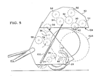
- Fig. 5 is a simplified side view of the preferred embodiment of the invention showing the means for ejecting the full sized bale from the baler.
- tailgate 60 When the bale 42 is fully formed, tailgate 60 is raised by hydraulic pistons 102 to the full open position 104 shown in Fig. 5. The raised position 104 of the tailgate 60 releases the bale 42 from the compressive forces of the rollers 30, 50, 32, 52, 34 and 54 which no longer have contact with the bale.
- the shifting rollers 26, 36 and 38 are, however, still in contact with the front surface of the bale 42 and the tension springs (not shown) on the rollers 36 and 38 pull them rearward, while that roller 26 is pulled upwardly, thus moving the bale 42 rearwardly in the process.
- the bale 42 thus pivots around the roller 48 and tips backward out of the baler.
- rollers both stationary and shifting, can be rotated by other conventional means such as hydraulic systems or gears, and restraining devices other than the tension springs 90 shown can be used to control the bale density.
- the diameters of the shifting rollers need not be identical nor must the diameters be the same as those of the stationary rollers.
- the paths of the shifting rollers can be other than circular orbits around the stationary rollers, and can be around some other convenient point of reference or can be other than circular.
- Independent hydraulic drives for each roller could eliminate virtually all restraints on the paths of the shifting rollers, so that the shifting rollers could be arranged to move through linear paths instead of orbital paths.
Landscapes
- Life Sciences & Earth Sciences (AREA)
- Environmental Sciences (AREA)
- Storage Of Harvested Produce (AREA)
Claims (16)
Applications Claiming Priority (2)
| Application Number | Priority Date | Filing Date | Title |
|---|---|---|---|
| US136668 | 1980-04-02 | ||
| US06/136,668 US4288971A (en) | 1980-04-02 | 1980-04-02 | Round baler |
Publications (2)
| Publication Number | Publication Date |
|---|---|
| EP0037155A1 EP0037155A1 (fr) | 1981-10-07 |
| EP0037155B1 true EP0037155B1 (fr) | 1984-05-23 |
Family
ID=22473840
Family Applications (1)
| Application Number | Title | Priority Date | Filing Date |
|---|---|---|---|
| EP81200340A Expired EP0037155B1 (fr) | 1980-04-02 | 1981-03-27 | Presse à balles cylindriques |
Country Status (4)
| Country | Link |
|---|---|
| US (1) | US4288971A (fr) |
| EP (1) | EP0037155B1 (fr) |
| CA (1) | CA1152376A (fr) |
| DE (1) | DE3163726D1 (fr) |
Families Citing this family (19)
| Publication number | Priority date | Publication date | Assignee | Title |
|---|---|---|---|---|
| DE3151580A1 (de) * | 1981-12-28 | 1983-07-07 | Claas Ohg, 4834 Harsewinkel | Rundballengrosspresse |
| EP0110110B1 (fr) * | 1982-10-27 | 1988-04-20 | DARIO MANULI S.p.A. | Dispositif pour envelopper en continu et hermétiquement un corps, en particulier une balle de foin |
| NL8301647A (nl) * | 1983-05-09 | 1984-12-03 | Multinorm Bv | Inrichting voor het tot een ronde baal vormen van gewas. |
| NL8304137A (nl) * | 1983-12-01 | 1985-07-01 | Lely Nv C Van Der | Inrichting voor het vormen van balen gewas. |
| NL191643C (nl) * | 1984-01-16 | 1995-12-02 | Lely Nv C Van Der | Inrichting voor het vormen van cilindervormige balen gewas. |
| FR2591850B1 (fr) * | 1985-12-20 | 1989-05-05 | Rivierre Casalis | Procede et dispositif de confection de balles cylindriques d'un produit agricole dans une presse ramasseuse. |
| GB2187414B (en) * | 1986-03-05 | 1989-11-15 | Deere & Co | Machine for forming cylindrical bales of crop |
| DE3668749D1 (de) * | 1986-10-21 | 1990-03-15 | Ford New Holland Inc | Rundballenpresse. |
| EP0264493B1 (fr) * | 1986-10-21 | 1989-12-20 | Ford New Holland N.V. | Presse à balles rondes |
| US4742768A (en) * | 1987-03-03 | 1988-05-10 | New Holland Inc. | System for monitoring bale shape in round balers |
| DE8802337U1 (de) * | 1988-02-23 | 1989-06-22 | P.J. Zweegers en Zonen, Landbouwmachinefabriek B.V., Geldrop | Rundballenpresse |
| DE19624718C2 (de) * | 1996-06-21 | 2002-10-31 | Claas Kgaa Mbh | Rundballenpresse |
| DE29706544U1 (de) * | 1997-04-11 | 1997-06-05 | Greenland Geldrop B.V., Geldrop | Rundballenpresse |
| DE29808383U1 (de) * | 1998-05-08 | 1998-08-06 | Multinorm B.V., Nieuw-Vennep | Rundballenpresse |
| DE10063120A1 (de) * | 2000-12-18 | 2002-06-20 | Deere & Co | Rundballenpresse |
| US9295198B2 (en) * | 2012-05-09 | 2016-03-29 | Cnh Industrial America Llc | Density system bypass for a round baler |
| NL2012073C2 (en) * | 2014-01-10 | 2015-07-13 | Forage Innovations Bv | Baling device to form bales of loose material having a hybrid baling chamber construction. |
| JP6333562B2 (ja) * | 2014-01-27 | 2018-05-30 | 株式会社タカキタ | ロールベーラー |
| US20250072333A1 (en) * | 2023-09-01 | 2025-03-06 | Cnh Industrial America Llc | Serpentine pivot roll |
Family Cites Families (10)
| Publication number | Priority date | Publication date | Assignee | Title |
|---|---|---|---|---|
| US1733434A (en) * | 1921-06-24 | 1929-10-29 | P M Clark | Cotton-baling process |
| US3827223A (en) * | 1973-04-24 | 1974-08-06 | Sperry Rand Corp | Hay roll forming machine |
| DE7430874U (de) * | 1974-09-13 | 1977-05-26 | Welger Geb | Aufsammel-rollballenpresse |
| US3968632A (en) * | 1974-10-02 | 1976-07-13 | Hesston Corporation | Machine for forming round bales |
| DE2602231A1 (de) * | 1976-01-22 | 1977-07-28 | Claas Maschf Gmbh Geb | Fahrbare grossballenpresse |
| US4019309A (en) * | 1976-03-05 | 1977-04-26 | Lundell Vernon J | Round bale forming machine |
| DE2658210A1 (de) * | 1976-12-22 | 1978-06-29 | Fahr Ag Maschf | Rollballenpresse |
| US4137697A (en) * | 1977-03-18 | 1979-02-06 | International Harvester Company | Bale density structure for cylindrical balers |
| US4159615A (en) * | 1977-11-02 | 1979-07-03 | Sperry Rand Corporation | Collection and recycling apparatus for crop material particles in a roll forming machine |
| US4205513A (en) * | 1978-08-03 | 1980-06-03 | John Shokoples | Ground-rolling forwardly-directed rotary baler |
-
1980
- 1980-04-02 US US06/136,668 patent/US4288971A/en not_active Expired - Lifetime
-
1981
- 1981-01-30 CA CA000369810A patent/CA1152376A/fr not_active Expired
- 1981-03-27 DE DE8181200340T patent/DE3163726D1/de not_active Expired
- 1981-03-27 EP EP81200340A patent/EP0037155B1/fr not_active Expired
Also Published As
| Publication number | Publication date |
|---|---|
| CA1152376A (fr) | 1983-08-23 |
| US4288971A (en) | 1981-09-15 |
| DE3163726D1 (en) | 1984-06-28 |
| EP0037155A1 (fr) | 1981-10-07 |
Similar Documents
| Publication | Publication Date | Title |
|---|---|---|
| EP0037155B1 (fr) | Presse à balles cylindriques | |
| EP0125719B1 (fr) | Presse à balles rondes | |
| US4176596A (en) | Machine for forming a round bale of fibrous agricultural material | |
| US4212149A (en) | Crop baling machines | |
| US4499714A (en) | Method of baling, and baling press | |
| US4597254A (en) | Continuous roll baler | |
| US4510741A (en) | Rotary crop baler | |
| EP3593627A1 (fr) | Mécanisme de tension constante de nouage de filet pour ramasseuses-enrouleuses | |
| IE52219B1 (en) | Agricultural machine for forming a round bale | |
| US4343141A (en) | Baling machine with improved arm assembly for controlling expansion of the upper apron | |
| EP0161726B1 (fr) | Presse à balles rondes | |
| US4229934A (en) | Bale rolling machine | |
| US4345421A (en) | Baling machine with a non-circular chamber | |
| US3132736A (en) | Bale thrower | |
| US4549480A (en) | Round baler with expanding bale chamber | |
| US4425753A (en) | Clutch mechanism for baling machine | |
| US3827223A (en) | Hay roll forming machine | |
| US5044272A (en) | Round baler with rollers and belts | |
| EP0120545B1 (fr) | Presse à balles rondes | |
| US4244166A (en) | Bale rolling machine | |
| US4016712A (en) | Machine for forming high density round bales | |
| US4584827A (en) | Drive mechanism for roll baler | |
| US4012892A (en) | Ground-rolled cylindrical baler | |
| US20200015423A1 (en) | Roll bales tying material feeding mechanism | |
| EP0255559A1 (fr) | Ramasseuse-enrouleuse continue et méthode |
Legal Events
| Date | Code | Title | Description |
|---|---|---|---|
| PUAI | Public reference made under article 153(3) epc to a published international application that has entered the european phase |
Free format text: ORIGINAL CODE: 0009012 |
|
| AK | Designated contracting states |
Designated state(s): DE FR GB |
|
| 17P | Request for examination filed |
Effective date: 19820312 |
|
| GRAA | (expected) grant |
Free format text: ORIGINAL CODE: 0009210 |
|
| AK | Designated contracting states |
Designated state(s): DE FR GB |
|
| REF | Corresponds to: |
Ref document number: 3163726 Country of ref document: DE Date of ref document: 19840628 |
|
| ET | Fr: translation filed | ||
| PLBE | No opposition filed within time limit |
Free format text: ORIGINAL CODE: 0009261 |
|
| STAA | Information on the status of an ep patent application or granted ep patent |
Free format text: STATUS: NO OPPOSITION FILED WITHIN TIME LIMIT |
|
| 26N | No opposition filed | ||
| PGFP | Annual fee paid to national office [announced via postgrant information from national office to epo] |
Ref country code: FR Payment date: 19900117 Year of fee payment: 10 |
|
| PGFP | Annual fee paid to national office [announced via postgrant information from national office to epo] |
Ref country code: DE Payment date: 19900131 Year of fee payment: 10 |
|
| PGFP | Annual fee paid to national office [announced via postgrant information from national office to epo] |
Ref country code: GB Payment date: 19900331 Year of fee payment: 10 |
|
| PG25 | Lapsed in a contracting state [announced via postgrant information from national office to epo] |
Ref country code: GB Effective date: 19910327 |
|
| GBPC | Gb: european patent ceased through non-payment of renewal fee | ||
| PG25 | Lapsed in a contracting state [announced via postgrant information from national office to epo] |
Ref country code: FR Effective date: 19911129 |
|
| PG25 | Lapsed in a contracting state [announced via postgrant information from national office to epo] |
Ref country code: DE Effective date: 19920101 |
|
| REG | Reference to a national code |
Ref country code: FR Ref legal event code: ST |