EP0037196A2 - Procédé et appareil pour déterminer des quantités physiques, en particulier des quantités par rapport à des longueurs - Google Patents
Procédé et appareil pour déterminer des quantités physiques, en particulier des quantités par rapport à des longueurs Download PDFInfo
- Publication number
- EP0037196A2 EP0037196A2 EP81301053A EP81301053A EP0037196A2 EP 0037196 A2 EP0037196 A2 EP 0037196A2 EP 81301053 A EP81301053 A EP 81301053A EP 81301053 A EP81301053 A EP 81301053A EP 0037196 A2 EP0037196 A2 EP 0037196A2
- Authority
- EP
- European Patent Office
- Prior art keywords
- receiver
- transmitter
- pulse
- parameter
- measured
- Prior art date
- Legal status (The legal status is an assumption and is not a legal conclusion. Google has not performed a legal analysis and makes no representation as to the accuracy of the status listed.)
- Granted
Links
Images

Classifications
-
- G—PHYSICS
- G01—MEASURING; TESTING
- G01S—RADIO DIRECTION-FINDING; RADIO NAVIGATION; DETERMINING DISTANCE OR VELOCITY BY USE OF RADIO WAVES; LOCATING OR PRESENCE-DETECTING BY USE OF THE REFLECTION OR RERADIATION OF RADIO WAVES; ANALOGOUS ARRANGEMENTS USING OTHER WAVES
- G01S11/00—Systems for determining distance or velocity not using reflection or reradiation
- G01S11/14—Systems for determining distance or velocity not using reflection or reradiation using ultrasonic, sonic or infrasonic waves
-
- G—PHYSICS
- G01—MEASURING; TESTING
- G01B—MEASURING LENGTH, THICKNESS OR SIMILAR LINEAR DIMENSIONS; MEASURING ANGLES; MEASURING AREAS; MEASURING IRREGULARITIES OF SURFACES OR CONTOURS
- G01B17/00—Measuring arrangements characterised by the use of infrasonic, sonic or ultrasonic vibrations
-
- G—PHYSICS
- G01—MEASURING; TESTING
- G01B—MEASURING LENGTH, THICKNESS OR SIMILAR LINEAR DIMENSIONS; MEASURING ANGLES; MEASURING AREAS; MEASURING IRREGULARITIES OF SURFACES OR CONTOURS
- G01B3/00—Measuring instruments characterised by the use of mechanical techniques
- G01B3/18—Micrometers
-
- G—PHYSICS
- G01—MEASURING; TESTING
- G01K—MEASURING TEMPERATURE; MEASURING QUANTITY OF HEAT; THERMALLY-SENSITIVE ELEMENTS NOT OTHERWISE PROVIDED FOR
- G01K11/00—Measuring temperature based upon physical or chemical changes not covered by groups G01K3/00, G01K5/00, G01K7/00 or G01K9/00
- G01K11/22—Measuring temperature based upon physical or chemical changes not covered by groups G01K3/00, G01K5/00, G01K7/00 or G01K9/00 using measurement of acoustic effects
- G01K11/24—Measuring temperature based upon physical or chemical changes not covered by groups G01K3/00, G01K5/00, G01K7/00 or G01K9/00 using measurement of acoustic effects of the velocity of propagation of sound
-
- Y—GENERAL TAGGING OF NEW TECHNOLOGICAL DEVELOPMENTS; GENERAL TAGGING OF CROSS-SECTIONAL TECHNOLOGIES SPANNING OVER SEVERAL SECTIONS OF THE IPC; TECHNICAL SUBJECTS COVERED BY FORMER USPC CROSS-REFERENCE ART COLLECTIONS [XRACs] AND DIGESTS
- Y10—TECHNICAL SUBJECTS COVERED BY FORMER USPC
- Y10S—TECHNICAL SUBJECTS COVERED BY FORMER USPC CROSS-REFERENCE ART COLLECTIONS [XRACs] AND DIGESTS
- Y10S367/00—Communications, electrical: acoustic wave systems and devices
- Y10S367/902—Speed of sound compensation
Definitions
- This invention relates to the monitoring length and other physical quantities, for example a distance between two locations which are movable relative to one another, and is applicable inter alia to machine tools and micrometers.
- One object of the present invention is to provide a length measuring apparatus and method which is relatively cheap to manufacture while providing a high degree of accuracy.
- Another object of the invention is to apply a similar technique to the monitoring of other parameters such as flow rate and temperature.
- one aspect of the invention provides a method of determining a physical parameter, comprising:
- the invention provides apparatus for determining a physical parameter, comprising:
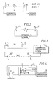
- a transmitting crystal 10 and a receiving crystal 12 are separated by a fluid medium (not shown) which may be water or light oil.
- a fluid medium (not shown) which may be water or light oil.
- An ultrasonic pulse is emitted into the fluid, and the distance x between the crystals 10 and 12 is measured from the relationship where t is the transit time, c is the speed of sound and Te is the response time of the electronics.
- the value of x can thus be derived from measurement of t.
- the resolution achieved is dependent on the sound wavelength and the response time e ; practical constraints on the electronics and acoustics limit the resolution to about lmm, or perhaps down to O.lmm with more advanced and therefore expensive hardware.
- the present invention also makes use of ultrasonic pulses transmitted through a fluid medium (not shown) between a transmitting crystal 10 and a receiving crystal 12.
- a retransmitting network 14 is provided whereby the receipt of a pulse triggers the transmission of a further pulse.
- T is the accumulated time interval
- n is the number of retransmissions.
- x can be determined by measuring T for a given n t (or vice versa).
- the resolution which can be achieved in practice with quite ordinary hardware is of the order of a fraction of a micron.
- Fig. 4 illustrates the mechanical arrangement of a preferred embodiment of the invention in the form of a micrometer.
- a frame 20 carries a fixed anvil 22 and a movable jaw 24, the distance between these being the distance x to be measured.
- the jaw 24 can be adjusted by screw 26.
- the frame 10 also forms a cavity 28 which is filled with a fluid medium, preferably light oil.
- Three pairs of ultrasonic transducers provide three acoustic paths in the fluid of lengths x l ,x 2 and x 3 .
- the principle of operation is as follows. Three time intervals: are measured, and each time interval is expressed as the number of clock pulses N 1 ,N 2 ,N 3 counted in a counter during the intervals T 1 ,T 2 ,T 3 .
- the numbers N 1 ,N 2 ,N 3 are then manipulated to give the result R as follows-.
- N 1 o ,N 2 o ,N 3 o are obtained with the micrometer zeroed
- K is a scale factor.
- the term is constant for a given micrometer and is stored in a continuous memory.
- the scale factor K can be determined by inserting a standard test piece in the micrometer, e.g. by inserting a test piece 25,000 ⁇ m thick and this result is also stored in the memory.
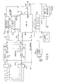
- Fig. 5 illustrates a suitable electronic system for the micrometer, the relevant waveforms being shown in F ig. 6.
- the basic operation is that the times T 1 , T 2 ,T 3 to count 2 12 pulses are measured sequentially, and R is calculated according to equation (7) above.
- a transmitter 40 is connected to drive one of three transmitting crystals in accordance with a multiplex control signal on line 42, and a receiver 44 is connected to one of three receiving crystals in dependence on the same multiplex control signal. Operation is started by a "ready" signal RDY 45 (Fig. 6A) on line 46 which triggers monostable 48 to produce a transmitter trigger signal 47 (Fig. 6B). Transmitter 40 produces a driving signal 41 (Fig. 6C) which excites the transmitting crystal to emit an ultrasonic pulse, which passes through the fluid and produces a signal 49 (Fig. 6D) from a receiver 50. The receiver signal 49 is level-detected by a Schmitt trigger 52 whose output 53 (Fig. 6E) triggers a monostable 54 to produce uniform pulses 55 (Fig. 6F). Each pulse 55 passes via OR-gate 56 to-trigger the monostable 48 and thus initiate a re-transmission of the acoustic pulse.
- the pulses 55 are also applied to a division circuit 58 in which division by 4096 is effected.
- the output 59 (Fig. 6G) or division circuit 58 is connected to AND gate 60 to enable clock pulses from a 455kHz clock circuit 62 to pass to a counter 64.
- the count held by the counter 64 after 4096 acoustic pulse transits across the length x is the number N 1 .
- the computation of R is suitably carried out in a microprocessor, in this example a Rockwell type "AIM 65" microprocessor 66.
- a microprocessor in this example a Rockwell type "AIM 65" microprocessor 66.
- the output of division circuit 58 is supplied on line 68 as an input to the microprocessor 66, and causes the count N held in the counter 64 to be input into the microprocessor 66 via a shift register 70, the counter 64 reset, and the multiplex control signal on line 42 advanced.
- the result R is displayed on any suitable display as indicated at 72.
- Fig. 5 also includes a conventional power supply 74 provided with on/off switch 76.
- Switch F 3 when closed provides a readout in inch units by switching in a circuit or program instruction to divide the result R by 2.54.
- a keyboard 78 provides keys F 1 ,F 2 for use when calibrating the instrument.
- the micrometer is closed and key F 1 depressed.
- the resulting value of No is stored in the microprocessor memory.
- the same procedure, using key F 2 is carried out with a known test piece to derive the scale factor K, which is also stored in memory. Since this procedure need be carried out only once to calibrate the instrument, the keyboard 78 may be temporarily plugged in during manufacture and not form part of the instrument in normal use.
- the above embodiment provides a highly accurate micrometer which -is essentially immune to temperature, ageing and drift. It also provides a very high resolution (typically about lpm) while using only relatively simple and cheap components.
- the ultrasonic transducers may be located in an oil-filled tube secured to a machine tool, the movable transducer being mechanically coupled to a moving part of the machine tool.
- the transmitting and receiving transducers can be located adjacent each other and the pulses reflected from transmitter to receiver by a movable reflector; obviously in this case it is necessary to disable the receiver briefly at the time of transmission, and to allow for the acoustic path being twice the distance of interest.
- the invention may also be applied to the measurement of parameters other than length.
- Weight may be measured by use of a spring or other resilient member of known load/displacement characteristic, the displacement of the spring under load being measured to calculate the weight.
- the flow rate of a liquid in a conduit may be measured by positioning fixed transmitters and receivers in the conduit.
- the time T in the conduit will be greater (or lesser) than a reference value in dependence on flow rate since the effective speed of sound c will be greater with increasing flow rate in the direction of transmission.
- the temperature of a liquid can be measured by providing acoustic paths of known length in the liquid of interest; the effect will be apparent from an examination of varying c in equation (2) above.
- pulses of other wave energy may be used, e.g. laser light.
Landscapes
- Physics & Mathematics (AREA)
- General Physics & Mathematics (AREA)
- Engineering & Computer Science (AREA)
- Radar, Positioning & Navigation (AREA)
- Remote Sensing (AREA)
- Acoustics & Sound (AREA)
- Length Measuring Devices Characterised By Use Of Acoustic Means (AREA)
- Length Measuring Devices With Unspecified Measuring Means (AREA)
- Measuring Pulse, Heart Rate, Blood Pressure Or Blood Flow (AREA)
- Eye Examination Apparatus (AREA)
- Measurement And Recording Of Electrical Phenomena And Electrical Characteristics Of The Living Body (AREA)
- Measurement Of Length, Angles, Or The Like Using Electric Or Magnetic Means (AREA)
Priority Applications (1)
| Application Number | Priority Date | Filing Date | Title |
|---|---|---|---|
| AT81301053T ATE34838T1 (de) | 1980-03-20 | 1981-03-13 | Verfahren und apparat zum bestimmen physikalischer groessen, insbesondere auf die laenge bezogener groessen. |
Applications Claiming Priority (4)
| Application Number | Priority Date | Filing Date | Title |
|---|---|---|---|
| GB8009495 | 1980-03-20 | ||
| GB8009495 | 1980-03-20 | ||
| GB8029414 | 1980-09-11 | ||
| GB8029414 | 1980-09-11 |
Publications (3)
| Publication Number | Publication Date |
|---|---|
| EP0037196A2 true EP0037196A2 (fr) | 1981-10-07 |
| EP0037196A3 EP0037196A3 (en) | 1982-08-04 |
| EP0037196B1 EP0037196B1 (fr) | 1988-06-01 |
Family
ID=26274902
Family Applications (1)
| Application Number | Title | Priority Date | Filing Date |
|---|---|---|---|
| EP81301053A Expired EP0037196B1 (fr) | 1980-03-20 | 1981-03-13 | Procédé et appareil pour déterminer des quantités physiques, en particulier des quantités par rapport à des longueurs |
Country Status (7)
| Country | Link |
|---|---|
| US (1) | US4388708A (fr) |
| EP (1) | EP0037196B1 (fr) |
| AT (1) | ATE34838T1 (fr) |
| AU (1) | AU537840B2 (fr) |
| CA (1) | CA1171951A (fr) |
| DE (1) | DE3176767D1 (fr) |
| IE (1) | IE54061B1 (fr) |
Cited By (10)
| Publication number | Priority date | Publication date | Assignee | Title |
|---|---|---|---|---|
| DE3116333A1 (de) * | 1981-04-24 | 1982-11-18 | H. Kuhnke Gmbh Kg, 2427 Malente | Messsystem zum beruehrungslosen erfassen von positionen der kolbenstange einer kolben-zylinder-einheit |
| WO1983003478A1 (fr) * | 1982-03-30 | 1983-10-13 | Martin Reuter | Procede et installation pour determiner une distance relative dans un dispositif a cylindre et piston |
| EP0092899A3 (fr) * | 1982-03-15 | 1984-12-27 | Jensen, Raymond Henry | Méthode et appareil pour la mesure de longueurs de tuyaux |
| FR2587477A1 (fr) * | 1985-09-19 | 1987-03-20 | Girardier Jean Pierre | Micrometre a affichage numerique |
| WO1989008235A1 (fr) * | 1988-03-04 | 1989-09-08 | Kiefer Klaus Juergen | Compas de mesure |
| WO1991008440A1 (fr) * | 1989-11-28 | 1991-06-13 | Mpv Mess- Und Prüftechnik Vogt Gmbh | Procede et dispositif pour la mesure de distance dans les gaz et les liquides par ultrasons |
| FR2683899A1 (fr) * | 1991-11-20 | 1993-05-21 | Siderurgie Fse Inst Rech | Procede et dispositif de mesure de la largeur d'une bande mince en defilement continu. |
| GB2262341A (en) * | 1991-12-10 | 1993-06-16 | Jones Richard W | Method and apparatus for measuring distances using an acoustic signal |
| DE19859202A1 (de) * | 1998-12-21 | 2000-07-13 | Trw Automotive Electron & Comp | Vorrichtung zur Abstandsmessung |
| FR2938926A1 (fr) * | 2008-11-26 | 2010-05-28 | Mcb Ind | Procede et systeme de mesure de distance et dispositif de reception associe |
Families Citing this family (7)
| Publication number | Priority date | Publication date | Assignee | Title |
|---|---|---|---|---|
| DE3608384A1 (de) * | 1986-03-13 | 1987-09-17 | F & O Electronic Systems | Verfahren zur messung von wegen, insbesondere zur absoluten messung von kleinen wegen, ueber die laufzeit von impulsen in einem materiellen traegermedium und zugehoerige vorrichtung zur durchfuehrung des verfahrens |
| US4938066A (en) * | 1988-01-29 | 1990-07-03 | Xecutek Corporation | Ultrasonic apparatus for measuring the speed of sound in a gaseous medium |
| US5031493A (en) * | 1988-03-07 | 1991-07-16 | Xecutek Corporation | Ultrasonic control system for cut-off or shearing machines |
| DE4336730A1 (de) * | 1993-10-28 | 1995-05-04 | Marquardt Gmbh | Elektrowerkzeug |
| JP2589046B2 (ja) * | 1993-11-01 | 1997-03-12 | 財団法人ダム水源地環境整備センター | 魚数計測方法と装置および移動体計数方法 |
| DE19738146B4 (de) * | 1997-09-01 | 2005-05-12 | Fresenius Ag | Ultraschallsender, insbesondere für einen Luftblasendetektor |
| GB0621532D0 (en) * | 2006-10-30 | 2006-12-06 | Jones Richard W | Apparatus for setting level measurement ultrasonic sensors |
Family Cites Families (9)
| Publication number | Priority date | Publication date | Assignee | Title |
|---|---|---|---|---|
| US2400309A (en) * | 1941-10-31 | 1946-05-14 | Baldwin Co | Oscillation generator |
| US2568926A (en) * | 1947-05-26 | 1951-09-25 | Moran Instr Corp | Distance measurement by echo ranging |
| GB889436A (en) * | 1957-04-27 | 1962-02-14 | Emi Ltd | Improvements relating to displacement measuring devices |
| US3076519A (en) * | 1958-12-18 | 1963-02-05 | Texas Instruments Inc | Ultrasonic surveyor's distance measuring instrument |
| US3115615A (en) * | 1960-08-16 | 1963-12-24 | Bogue Elec Mfg Co | Measuring systems |
| US3100885A (en) * | 1961-08-14 | 1963-08-13 | Gulton Ind Inc | Ultrasonic liquid level gauge |
| US3508046A (en) * | 1964-07-15 | 1970-04-21 | Eon Corp | Range measuring apparatus using radioactive material |
| US3503680A (en) * | 1967-03-31 | 1970-03-31 | Perkin Elmer Corp | Range measuring system |
| GB1525720A (en) * | 1975-12-20 | 1978-09-20 | Univ Cardiff | Distance measuring apparatus |
-
1981
- 1981-03-13 EP EP81301053A patent/EP0037196B1/fr not_active Expired
- 1981-03-13 AT AT81301053T patent/ATE34838T1/de not_active IP Right Cessation
- 1981-03-13 DE DE8181301053T patent/DE3176767D1/de not_active Expired
- 1981-03-18 US US06/244,962 patent/US4388708A/en not_active Expired - Fee Related
- 1981-03-18 AU AU68510/81A patent/AU537840B2/en not_active Ceased
- 1981-03-19 CA CA000373418A patent/CA1171951A/fr not_active Expired
- 1981-03-19 IE IE611/81A patent/IE54061B1/en unknown
Cited By (13)
| Publication number | Priority date | Publication date | Assignee | Title |
|---|---|---|---|---|
| DE3116333A1 (de) * | 1981-04-24 | 1982-11-18 | H. Kuhnke Gmbh Kg, 2427 Malente | Messsystem zum beruehrungslosen erfassen von positionen der kolbenstange einer kolben-zylinder-einheit |
| EP0092899A3 (fr) * | 1982-03-15 | 1984-12-27 | Jensen, Raymond Henry | Méthode et appareil pour la mesure de longueurs de tuyaux |
| WO1983003478A1 (fr) * | 1982-03-30 | 1983-10-13 | Martin Reuter | Procede et installation pour determiner une distance relative dans un dispositif a cylindre et piston |
| US4542652A (en) * | 1982-03-30 | 1985-09-24 | Martin Reuter | Method and apparatus for determining a relative distance in a cylinder and piston assembly |
| FR2587477A1 (fr) * | 1985-09-19 | 1987-03-20 | Girardier Jean Pierre | Micrometre a affichage numerique |
| WO1987001797A1 (fr) * | 1985-09-19 | 1987-03-26 | Girardier Jean Pierre | Micrometre a affichage numerique |
| WO1989008235A1 (fr) * | 1988-03-04 | 1989-09-08 | Kiefer Klaus Juergen | Compas de mesure |
| DE3990155C1 (de) * | 1988-03-04 | 1998-08-06 | Klaus Juergen Kiefer | Meßzirkel |
| WO1991008440A1 (fr) * | 1989-11-28 | 1991-06-13 | Mpv Mess- Und Prüftechnik Vogt Gmbh | Procede et dispositif pour la mesure de distance dans les gaz et les liquides par ultrasons |
| FR2683899A1 (fr) * | 1991-11-20 | 1993-05-21 | Siderurgie Fse Inst Rech | Procede et dispositif de mesure de la largeur d'une bande mince en defilement continu. |
| GB2262341A (en) * | 1991-12-10 | 1993-06-16 | Jones Richard W | Method and apparatus for measuring distances using an acoustic signal |
| DE19859202A1 (de) * | 1998-12-21 | 2000-07-13 | Trw Automotive Electron & Comp | Vorrichtung zur Abstandsmessung |
| FR2938926A1 (fr) * | 2008-11-26 | 2010-05-28 | Mcb Ind | Procede et systeme de mesure de distance et dispositif de reception associe |
Also Published As
| Publication number | Publication date |
|---|---|
| IE54061B1 (en) | 1989-06-07 |
| EP0037196A3 (en) | 1982-08-04 |
| AU6851081A (en) | 1981-09-24 |
| US4388708A (en) | 1983-06-14 |
| EP0037196B1 (fr) | 1988-06-01 |
| DE3176767D1 (en) | 1988-07-07 |
| CA1171951A (fr) | 1984-07-31 |
| AU537840B2 (en) | 1984-07-12 |
| IE810611L (en) | 1982-09-19 |
| ATE34838T1 (de) | 1988-06-15 |
Similar Documents
| Publication | Publication Date | Title |
|---|---|---|
| US4388708A (en) | Method and apparatus for determining physical quantities | |
| CA1126384A (fr) | Methode et instrument d'etalonnage au zero pour calibre d'epaisseur ultrasonique | |
| US4114455A (en) | Ultrasonic velocity measuring method and apparatus | |
| SE8800097L (sv) | Foerfarande foer att faststaella en upptraedande diskrepans mellan tvaa optiska vaegstraeckor samt anordning anpassad foer utfoerande av foerfarandet | |
| JPH0961145A (ja) | 厚さまたは音速の測定方法および測定装置 | |
| SU1673861A1 (ru) | Способ настройки акустических уровнемеров | |
| SU794492A1 (ru) | Устройство дл определени проч-НОСТи бЕТОНА | |
| JPH02116745A (ja) | 超音波溶液濃度測定装置 | |
| SU1661573A1 (ru) | Акустический гидростатический нивелир | |
| SU811137A1 (ru) | Способ определени скоростиульТРАзВуКА | |
| SU930169A1 (ru) | Способ определени рассто ни до места повреждени линии св зи | |
| SU932274A1 (ru) | Устройство дл измерени времени распространени ультразвука | |
| JPH04313010A (ja) | 厚さ測定方法およびその装置 | |
| SU1068716A1 (ru) | Ультразвуковой способ измерени скорости потока и расходомер дл его осуществлени | |
| JPH1010230A (ja) | 距離計測装置 | |
| JPH08334321A (ja) | 超音波式測距計 | |
| SU1307325A1 (ru) | Измеритель скорости ультразвука | |
| SU690310A1 (ru) | Цифровой акустический уровнемер | |
| SU1439412A1 (ru) | Способ измерени вибрационного ускорени и устройство дл его осуществлени | |
| SU548834A1 (ru) | Устройство дл измерени сдвига шкал времени | |
| SU1065707A1 (ru) | Устройство дл градуировки преобразователей давлени | |
| SU962809A1 (ru) | Устройство дл определени прочности бетона | |
| JPH0123048B2 (fr) | ||
| SU998860A1 (ru) | Способ акустического контрол толщины оболочек | |
| SU1008620A1 (ru) | Ультразвуковой уровнемер |
Legal Events
| Date | Code | Title | Description |
|---|---|---|---|
| PUAI | Public reference made under article 153(3) epc to a published international application that has entered the european phase |
Free format text: ORIGINAL CODE: 0009012 |
|
| AK | Designated contracting states |
Designated state(s): AT BE CH DE FR GB IT LU NL SE |
|
| 17P | Request for examination filed |
Effective date: 19820304 |
|
| PUAL | Search report despatched |
Free format text: ORIGINAL CODE: 0009013 |
|
| AK | Designated contracting states |
Designated state(s): AT BE CH DE FR GB IT LU NL SE |
|
| RAP1 | Party data changed (applicant data changed or rights of an application transferred) |
Owner name: ACUMET PRECISION INSTRUMENTS LTD |
|
| RIN1 | Information on inventor provided before grant (corrected) |
Inventor name: STRACHAN, JOHN SCOTT Inventor name: SKRGATIC, DAMIR MIROSLAV JOSIP |
|
| GRAA | (expected) grant |
Free format text: ORIGINAL CODE: 0009210 |
|
| AK | Designated contracting states |
Kind code of ref document: B1 Designated state(s): AT BE CH DE FR GB IT LI LU NL SE |
|
| PG25 | Lapsed in a contracting state [announced via postgrant information from national office to epo] |
Ref country code: LI Effective date: 19880601 Ref country code: CH Effective date: 19880601 |
|
| REF | Corresponds to: |
Ref document number: 34838 Country of ref document: AT Date of ref document: 19880615 Kind code of ref document: T |
|
| PG25 | Lapsed in a contracting state [announced via postgrant information from national office to epo] |
Ref country code: SE Effective date: 19880630 |
|
| REF | Corresponds to: |
Ref document number: 3176767 Country of ref document: DE Date of ref document: 19880707 |
|
| ITF | It: translation for a ep patent filed | ||
| REG | Reference to a national code |
Ref country code: CH Ref legal event code: PL |
|
| ET | Fr: translation filed | ||
| PG25 | Lapsed in a contracting state [announced via postgrant information from national office to epo] |
Ref country code: LU Free format text: LAPSE BECAUSE OF NON-PAYMENT OF DUE FEES Effective date: 19890331 |
|
| PLBE | No opposition filed within time limit |
Free format text: ORIGINAL CODE: 0009261 |
|
| STAA | Information on the status of an ep patent application or granted ep patent |
Free format text: STATUS: NO OPPOSITION FILED WITHIN TIME LIMIT |
|
| 26N | No opposition filed | ||
| PGFP | Annual fee paid to national office [announced via postgrant information from national office to epo] |
Ref country code: FR Payment date: 19900223 Year of fee payment: 10 Ref country code: AT Payment date: 19900223 Year of fee payment: 10 |
|
| PGFP | Annual fee paid to national office [announced via postgrant information from national office to epo] |
Ref country code: BE Payment date: 19900228 Year of fee payment: 10 |
|
| ITTA | It: last paid annual fee | ||
| PGFP | Annual fee paid to national office [announced via postgrant information from national office to epo] |
Ref country code: NL Payment date: 19900331 Year of fee payment: 10 Ref country code: GB Payment date: 19900331 Year of fee payment: 10 |
|
| PGFP | Annual fee paid to national office [announced via postgrant information from national office to epo] |
Ref country code: DE Payment date: 19900419 Year of fee payment: 10 |
|
| PG25 | Lapsed in a contracting state [announced via postgrant information from national office to epo] |
Ref country code: GB Effective date: 19910313 Ref country code: AT Effective date: 19910313 |
|
| PG25 | Lapsed in a contracting state [announced via postgrant information from national office to epo] |
Ref country code: BE Effective date: 19910331 |
|
| BERE | Be: lapsed |
Owner name: ACUMET PRECISION INSTRUMENTS LTD Effective date: 19910331 |
|
| PG25 | Lapsed in a contracting state [announced via postgrant information from national office to epo] |
Ref country code: NL Effective date: 19911001 |
|
| GBPC | Gb: european patent ceased through non-payment of renewal fee | ||
| NLV4 | Nl: lapsed or anulled due to non-payment of the annual fee | ||
| PG25 | Lapsed in a contracting state [announced via postgrant information from national office to epo] |
Ref country code: FR Effective date: 19911129 |
|
| PG25 | Lapsed in a contracting state [announced via postgrant information from national office to epo] |
Ref country code: DE Effective date: 19920101 |
|
| REG | Reference to a national code |
Ref country code: FR Ref legal event code: ST |