EP0037266A2 - Verfahren und Vorrichtung zur Temperaturkontrolle oder Anzeige der Anwesenheit eines Materials mittels eines Lichtwellenleiters, Hitze-aktivierbare, Lichtleiter umfassende Artikel sowie Lichtleiter und Verfahren zur Herstellung solcher Lichtleiter - Google Patents
Verfahren und Vorrichtung zur Temperaturkontrolle oder Anzeige der Anwesenheit eines Materials mittels eines Lichtwellenleiters, Hitze-aktivierbare, Lichtleiter umfassende Artikel sowie Lichtleiter und Verfahren zur Herstellung solcher Lichtleiter Download PDFInfo
- Publication number
- EP0037266A2 EP0037266A2 EP81301336A EP81301336A EP0037266A2 EP 0037266 A2 EP0037266 A2 EP 0037266A2 EP 81301336 A EP81301336 A EP 81301336A EP 81301336 A EP81301336 A EP 81301336A EP 0037266 A2 EP0037266 A2 EP 0037266A2
- Authority
- EP
- European Patent Office
- Prior art keywords
- waveguide
- temperature
- core
- cladding
- blackout
- Prior art date
- Legal status (The legal status is an assumption and is not a legal conclusion. Google has not performed a legal analysis and makes no representation as to the accuracy of the status listed.)
- Withdrawn
Links
- 239000000463 material Substances 0.000 title claims abstract description 135
- 238000000034 method Methods 0.000 title claims abstract description 44
- 238000004519 manufacturing process Methods 0.000 title description 4
- 238000005253 cladding Methods 0.000 claims abstract description 222
- 230000008859 change Effects 0.000 claims abstract description 56
- -1 dimethylsiloxane Chemical class 0.000 claims description 41
- KPUWHANPEXNPJT-UHFFFAOYSA-N disiloxane Chemical class [SiH3]O[SiH3] KPUWHANPEXNPJT-UHFFFAOYSA-N 0.000 claims description 30
- 239000012530 fluid Substances 0.000 claims description 27
- 239000007788 liquid Substances 0.000 claims description 24
- 125000001997 phenyl group Chemical group [H]C1=C([H])C([H])=C(*)C([H])=C1[H] 0.000 claims description 24
- 239000000835 fiber Substances 0.000 claims description 21
- 238000002844 melting Methods 0.000 claims description 19
- 230000008018 melting Effects 0.000 claims description 19
- 239000002019 doping agent Substances 0.000 claims description 17
- 238000004891 communication Methods 0.000 claims description 14
- 238000012544 monitoring process Methods 0.000 claims description 14
- 229920001921 poly-methyl-phenyl-siloxane Polymers 0.000 claims description 13
- 229920001577 copolymer Polymers 0.000 claims description 11
- 125000000217 alkyl group Chemical group 0.000 claims description 9
- 238000010438 heat treatment Methods 0.000 claims description 7
- 229920006294 polydialkylsiloxane Polymers 0.000 claims description 7
- 229920000642 polymer Polymers 0.000 claims description 7
- 238000013459 approach Methods 0.000 claims description 6
- 238000001816 cooling Methods 0.000 claims description 6
- 230000001747 exhibiting effect Effects 0.000 claims description 6
- 125000002496 methyl group Chemical group [H]C([H])([H])* 0.000 claims description 6
- 125000004432 carbon atom Chemical group C* 0.000 claims description 5
- 230000007423 decrease Effects 0.000 claims description 5
- 239000000758 substrate Substances 0.000 claims description 5
- IAYPIBMASNFSPL-UHFFFAOYSA-N Ethylene oxide Chemical compound C1CO1 IAYPIBMASNFSPL-UHFFFAOYSA-N 0.000 claims description 4
- 238000011065 in-situ storage Methods 0.000 claims description 4
- 239000000203 mixture Substances 0.000 claims description 4
- VCYDUTCMKSROID-UHFFFAOYSA-N 2,2,4,4,6,6-hexakis-phenyl-1,3,5,2,4,6-trioxatrisilinane Chemical compound O1[Si](C=2C=CC=CC=2)(C=2C=CC=CC=2)O[Si](C=2C=CC=CC=2)(C=2C=CC=CC=2)O[Si]1(C=1C=CC=CC=1)C1=CC=CC=C1 VCYDUTCMKSROID-UHFFFAOYSA-N 0.000 claims description 3
- YQULWRCMYAXEAV-UHFFFAOYSA-N chloro-[chloro(diphenyl)silyl]oxy-diphenylsilane Chemical compound C=1C=CC=CC=1[Si](C=1C=CC=CC=1)(Cl)O[Si](Cl)(C=1C=CC=CC=1)C1=CC=CC=C1 YQULWRCMYAXEAV-UHFFFAOYSA-N 0.000 claims description 3
- 238000010894 electron beam technology Methods 0.000 claims description 3
- 125000001495 ethyl group Chemical group [H]C([H])([H])C([H])([H])* 0.000 claims description 3
- 125000001436 propyl group Chemical group [H]C([*])([H])C([H])([H])C([H])([H])[H] 0.000 claims description 3
- JLAVCPKULITDHO-UHFFFAOYSA-N tetraphenylsilane Chemical compound C1=CC=CC=C1[Si](C=1C=CC=CC=1)(C=1C=CC=CC=1)C1=CC=CC=C1 JLAVCPKULITDHO-UHFFFAOYSA-N 0.000 claims description 3
- ZODWTWYKYYGSFS-UHFFFAOYSA-N diphenyl-bis(prop-2-enyl)silane Chemical compound C=1C=CC=CC=1[Si](CC=C)(CC=C)C1=CC=CC=C1 ZODWTWYKYYGSFS-UHFFFAOYSA-N 0.000 claims description 2
- 150000002825 nitriles Chemical class 0.000 claims description 2
- 229920001296 polysiloxane Polymers 0.000 claims 5
- BGHCVCJVXZWKCC-UHFFFAOYSA-N tetradecane Chemical compound CCCCCCCCCCCCCC BGHCVCJVXZWKCC-UHFFFAOYSA-N 0.000 claims 4
- 230000005540 biological transmission Effects 0.000 abstract description 21
- 230000003287 optical effect Effects 0.000 abstract description 3
- 239000011162 core material Substances 0.000 description 85
- VYPSYNLAJGMNEJ-UHFFFAOYSA-N Silicium dioxide Chemical group O=[Si]=O VYPSYNLAJGMNEJ-UHFFFAOYSA-N 0.000 description 52
- 239000010410 layer Substances 0.000 description 30
- 239000000377 silicon dioxide Substances 0.000 description 18
- 239000004205 dimethyl polysiloxane Substances 0.000 description 14
- 235000013870 dimethyl polysiloxane Nutrition 0.000 description 14
- 238000007710 freezing Methods 0.000 description 14
- 230000008014 freezing Effects 0.000 description 14
- 229920000435 poly(dimethylsiloxane) Polymers 0.000 description 14
- XLYOFNOQVPJJNP-UHFFFAOYSA-N water Substances O XLYOFNOQVPJJNP-UHFFFAOYSA-N 0.000 description 12
- YXFVVABEGXRONW-UHFFFAOYSA-N Toluene Chemical compound CC1=CC=CC=C1 YXFVVABEGXRONW-UHFFFAOYSA-N 0.000 description 6
- 238000002425 crystallisation Methods 0.000 description 6
- 230000008025 crystallization Effects 0.000 description 6
- 239000011521 glass Substances 0.000 description 6
- BQCIDUSAKPWEOX-UHFFFAOYSA-N 1,1-Difluoroethene Chemical compound FC(F)=C BQCIDUSAKPWEOX-UHFFFAOYSA-N 0.000 description 5
- 238000006467 substitution reaction Methods 0.000 description 5
- KFZMGEQAYNKOFK-UHFFFAOYSA-N Isopropanol Chemical compound CC(C)O KFZMGEQAYNKOFK-UHFFFAOYSA-N 0.000 description 4
- 229920006370 Kynar Polymers 0.000 description 4
- 239000000853 adhesive Substances 0.000 description 4
- 230000001070 adhesive effect Effects 0.000 description 4
- 230000008901 benefit Effects 0.000 description 4
- 239000006229 carbon black Substances 0.000 description 4
- 230000002427 irreversible effect Effects 0.000 description 4
- VZGDMQKNWNREIO-UHFFFAOYSA-N tetrachloromethane Chemical compound ClC(Cl)(Cl)Cl VZGDMQKNWNREIO-UHFFFAOYSA-N 0.000 description 4
- 239000003963 antioxidant agent Substances 0.000 description 3
- 230000003078 antioxidant effect Effects 0.000 description 3
- 238000009835 boiling Methods 0.000 description 3
- 230000003247 decreasing effect Effects 0.000 description 3
- 125000004435 hydrogen atom Chemical group [H]* 0.000 description 3
- 238000002156 mixing Methods 0.000 description 3
- IJGRMHOSHXDMSA-UHFFFAOYSA-N nitrogen Substances N#N IJGRMHOSHXDMSA-UHFFFAOYSA-N 0.000 description 3
- 239000013307 optical fiber Substances 0.000 description 3
- 239000000243 solution Substances 0.000 description 3
- HFDVRLIODXPAHB-UHFFFAOYSA-N 1-tetradecene Chemical group CCCCCCCCCCCCC=C HFDVRLIODXPAHB-UHFFFAOYSA-N 0.000 description 2
- 239000005046 Chlorosilane Substances 0.000 description 2
- 239000003377 acid catalyst Substances 0.000 description 2
- 230000004913 activation Effects 0.000 description 2
- 239000012790 adhesive layer Substances 0.000 description 2
- 238000000149 argon plasma sintering Methods 0.000 description 2
- 229920002678 cellulose Polymers 0.000 description 2
- 238000000576 coating method Methods 0.000 description 2
- 238000010276 construction Methods 0.000 description 2
- 230000000694 effects Effects 0.000 description 2
- 238000002839 fiber optic waveguide Methods 0.000 description 2
- 239000007789 gas Substances 0.000 description 2
- 239000003365 glass fiber Substances 0.000 description 2
- 239000003949 liquefied natural gas Substances 0.000 description 2
- 229910052757 nitrogen Inorganic materials 0.000 description 2
- 239000003921 oil Substances 0.000 description 2
- 238000013021 overheating Methods 0.000 description 2
- 239000003208 petroleum Substances 0.000 description 2
- 229920003229 poly(methyl methacrylate) Polymers 0.000 description 2
- 239000004926 polymethyl methacrylate Substances 0.000 description 2
- 238000002360 preparation method Methods 0.000 description 2
- 230000008569 process Effects 0.000 description 2
- 238000005086 pumping Methods 0.000 description 2
- 229910000679 solder Inorganic materials 0.000 description 2
- BFKJFAAPBSQJPD-UHFFFAOYSA-N tetrafluoroethene Chemical group FC(F)=C(F)F BFKJFAAPBSQJPD-UHFFFAOYSA-N 0.000 description 2
- KYVBNYUBXIEUFW-UHFFFAOYSA-N 1,1,3,3-tetramethylguanidine Chemical compound CN(C)C(=N)N(C)C KYVBNYUBXIEUFW-UHFFFAOYSA-N 0.000 description 1
- DLKQHBOKULLWDQ-UHFFFAOYSA-N 1-bromonaphthalene Chemical compound C1=CC=C2C(Br)=CC=CC2=C1 DLKQHBOKULLWDQ-UHFFFAOYSA-N 0.000 description 1
- UJSBHHZJPDHGHQ-UHFFFAOYSA-N 2,2,4,4-tetraphenyl-1,3,5,2,4,6-trioxatrisilinane Chemical compound C1(=CC=CC=C1)[Si]1(O[Si](O[SiH2]O1)(C1=CC=CC=C1)C1=CC=CC=C1)C1=CC=CC=C1 UJSBHHZJPDHGHQ-UHFFFAOYSA-N 0.000 description 1
- QLEMFNDSSPDDRW-UHFFFAOYSA-N 2,2-dimethyl-4,4,6,6-tetraphenyl-1,3,5,2,4,6-trioxatrisilinane Chemical compound O1[Si](C)(C)O[Si](C=2C=CC=CC=2)(C=2C=CC=CC=2)O[Si]1(C=1C=CC=CC=1)C1=CC=CC=C1 QLEMFNDSSPDDRW-UHFFFAOYSA-N 0.000 description 1
- 108010053481 Antifreeze Proteins Proteins 0.000 description 1
- KRHYYFGTRYWZRS-UHFFFAOYSA-N Fluorane Chemical group F KRHYYFGTRYWZRS-UHFFFAOYSA-N 0.000 description 1
- KRHYYFGTRYWZRS-UHFFFAOYSA-M Fluoride anion Chemical compound [F-] KRHYYFGTRYWZRS-UHFFFAOYSA-M 0.000 description 1
- DGAQECJNVWCQMB-PUAWFVPOSA-M Ilexoside XXIX Chemical compound C[C@@H]1CC[C@@]2(CC[C@@]3(C(=CC[C@H]4[C@]3(CC[C@@H]5[C@@]4(CC[C@@H](C5(C)C)OS(=O)(=O)[O-])C)C)[C@@H]2[C@]1(C)O)C)C(=O)O[C@H]6[C@@H]([C@H]([C@@H]([C@H](O6)CO)O)O)O.[Na+] DGAQECJNVWCQMB-PUAWFVPOSA-M 0.000 description 1
- OWYWGLHRNBIFJP-UHFFFAOYSA-N Ipazine Chemical compound CCN(CC)C1=NC(Cl)=NC(NC(C)C)=N1 OWYWGLHRNBIFJP-UHFFFAOYSA-N 0.000 description 1
- 239000002033 PVDF binder Substances 0.000 description 1
- 229920003171 Poly (ethylene oxide) Polymers 0.000 description 1
- BGYHLZZASRKEJE-UHFFFAOYSA-N [3-[3-(3,5-ditert-butyl-4-hydroxyphenyl)propanoyloxy]-2,2-bis[3-(3,5-ditert-butyl-4-hydroxyphenyl)propanoyloxymethyl]propyl] 3-(3,5-ditert-butyl-4-hydroxyphenyl)propanoate Chemical compound CC(C)(C)C1=C(O)C(C(C)(C)C)=CC(CCC(=O)OCC(COC(=O)CCC=2C=C(C(O)=C(C=2)C(C)(C)C)C(C)(C)C)(COC(=O)CCC=2C=C(C(O)=C(C=2)C(C)(C)C)C(C)(C)C)COC(=O)CCC=2C=C(C(O)=C(C=2)C(C)(C)C)C(C)(C)C)=C1 BGYHLZZASRKEJE-UHFFFAOYSA-N 0.000 description 1
- 239000002253 acid Substances 0.000 description 1
- 239000000654 additive Substances 0.000 description 1
- 150000001336 alkenes Chemical class 0.000 description 1
- 230000002528 anti-freeze Effects 0.000 description 1
- 239000007864 aqueous solution Substances 0.000 description 1
- 238000005452 bending Methods 0.000 description 1
- OJIJEKBXJYRIBZ-UHFFFAOYSA-N cadmium nickel Chemical compound [Ni].[Cd] OJIJEKBXJYRIBZ-UHFFFAOYSA-N 0.000 description 1
- YCITZMJNBYYMJO-UHFFFAOYSA-N chloro(diphenyl)silicon Chemical compound C=1C=CC=CC=1[Si](Cl)C1=CC=CC=C1 YCITZMJNBYYMJO-UHFFFAOYSA-N 0.000 description 1
- KOPOQZFJUQMUML-UHFFFAOYSA-N chlorosilane Chemical compound Cl[SiH3] KOPOQZFJUQMUML-UHFFFAOYSA-N 0.000 description 1
- 239000011248 coating agent Substances 0.000 description 1
- 238000004040 coloring Methods 0.000 description 1
- 229920001940 conductive polymer Polymers 0.000 description 1
- 239000000356 contaminant Substances 0.000 description 1
- 230000001276 controlling effect Effects 0.000 description 1
- 238000004132 cross linking Methods 0.000 description 1
- 239000003431 cross linking reagent Substances 0.000 description 1
- 239000002178 crystalline material Substances 0.000 description 1
- 238000011161 development Methods 0.000 description 1
- 150000002148 esters Chemical group 0.000 description 1
- 238000004880 explosion Methods 0.000 description 1
- 229910052731 fluorine Inorganic materials 0.000 description 1
- 239000011737 fluorine Substances 0.000 description 1
- 125000001153 fluoro group Chemical group F* 0.000 description 1
- 229910021485 fumed silica Inorganic materials 0.000 description 1
- 239000002654 heat shrinkable material Substances 0.000 description 1
- CPBQJMYROZQQJC-UHFFFAOYSA-N helium neon Chemical compound [He].[Ne] CPBQJMYROZQQJC-UHFFFAOYSA-N 0.000 description 1
- 229920001519 homopolymer Polymers 0.000 description 1
- 239000001257 hydrogen Substances 0.000 description 1
- 229910052739 hydrogen Inorganic materials 0.000 description 1
- 239000013521 mastic Substances 0.000 description 1
- 238000005259 measurement Methods 0.000 description 1
- 229910052751 metal Inorganic materials 0.000 description 1
- 239000002184 metal Substances 0.000 description 1
- VNWKTOKETHGBQD-UHFFFAOYSA-N methane Chemical compound C VNWKTOKETHGBQD-UHFFFAOYSA-N 0.000 description 1
- QJGQUHMNIGDVPM-UHFFFAOYSA-N nitrogen(.) Chemical compound [N] QJGQUHMNIGDVPM-UHFFFAOYSA-N 0.000 description 1
- 239000002667 nucleating agent Substances 0.000 description 1
- 239000012188 paraffin wax Substances 0.000 description 1
- 239000003209 petroleum derivative Substances 0.000 description 1
- 238000006116 polymerization reaction Methods 0.000 description 1
- 229920002981 polyvinylidene fluoride Polymers 0.000 description 1
- 239000010453 quartz Substances 0.000 description 1
- 230000001105 regulatory effect Effects 0.000 description 1
- 230000002441 reversible effect Effects 0.000 description 1
- 238000006748 scratching Methods 0.000 description 1
- 230000002393 scratching effect Effects 0.000 description 1
- 238000007789 sealing Methods 0.000 description 1
- 229910052708 sodium Inorganic materials 0.000 description 1
- 239000011734 sodium Substances 0.000 description 1
- 239000007787 solid Substances 0.000 description 1
- 239000007858 starting material Substances 0.000 description 1
- 238000004781 supercooling Methods 0.000 description 1
- 229940095068 tetradecene Drugs 0.000 description 1
- UFHILTCGAOPTOV-UHFFFAOYSA-N tetrakis(ethenyl)silane Chemical compound C=C[Si](C=C)(C=C)C=C UFHILTCGAOPTOV-UHFFFAOYSA-N 0.000 description 1
- 125000000725 trifluoropropyl group Chemical group [H]C([H])(*)C([H])([H])C(F)(F)F 0.000 description 1
- 238000000870 ultraviolet spectroscopy Methods 0.000 description 1
- 125000000391 vinyl group Chemical group [H]C([*])=C([H])[H] 0.000 description 1
- 229920002554 vinyl polymer Polymers 0.000 description 1
Images


Classifications
-
- G—PHYSICS
- G01—MEASURING; TESTING
- G01M—TESTING STATIC OR DYNAMIC BALANCE OF MACHINES OR STRUCTURES; TESTING OF STRUCTURES OR APPARATUS, NOT OTHERWISE PROVIDED FOR
- G01M3/00—Investigating fluid-tightness of structures
- G01M3/02—Investigating fluid-tightness of structures by using fluid or vacuum
- G01M3/04—Investigating fluid-tightness of structures by using fluid or vacuum by detecting the presence of fluid at the leakage point
- G01M3/042—Investigating fluid-tightness of structures by using fluid or vacuum by detecting the presence of fluid at the leakage point by using materials which expand, contract, disintegrate, or decompose in contact with a fluid
- G01M3/045—Investigating fluid-tightness of structures by using fluid or vacuum by detecting the presence of fluid at the leakage point by using materials which expand, contract, disintegrate, or decompose in contact with a fluid with electrical detection means
- G01M3/047—Investigating fluid-tightness of structures by using fluid or vacuum by detecting the presence of fluid at the leakage point by using materials which expand, contract, disintegrate, or decompose in contact with a fluid with electrical detection means with photo-electrical detection means, e.g. using optical fibres
-
- G—PHYSICS
- G01—MEASURING; TESTING
- G01K—MEASURING TEMPERATURE; MEASURING QUANTITY OF HEAT; THERMALLY-SENSITIVE ELEMENTS NOT OTHERWISE PROVIDED FOR
- G01K11/00—Measuring temperature based upon physical or chemical changes not covered by groups G01K3/00, G01K5/00, G01K7/00 or G01K9/00
- G01K11/32—Measuring temperature based upon physical or chemical changes not covered by groups G01K3/00, G01K5/00, G01K7/00 or G01K9/00 using changes in transmittance, scattering or luminescence in optical fibres
-
- G—PHYSICS
- G01—MEASURING; TESTING
- G01K—MEASURING TEMPERATURE; MEASURING QUANTITY OF HEAT; THERMALLY-SENSITIVE ELEMENTS NOT OTHERWISE PROVIDED FOR
- G01K3/00—Thermometers giving results other than momentary value of temperature
-
- G—PHYSICS
- G01—MEASURING; TESTING
- G01M—TESTING STATIC OR DYNAMIC BALANCE OF MACHINES OR STRUCTURES; TESTING OF STRUCTURES OR APPARATUS, NOT OTHERWISE PROVIDED FOR
- G01M3/00—Investigating fluid-tightness of structures
- G01M3/002—Investigating fluid-tightness of structures by using thermal means
Definitions
- the present invention is directed to methods for using fiber optic waveguides for temperature monitoring.
- the present invention provides a method of controlling the temperature of a material comprising the steps of:
- Another aspect of the present invention provides a method of indicating the presence or absence of a material comprising the steps of:
- the waveguides referred to herein comprise a core and a cladding disposed on and around the',exterior surface of the core, where at least a portion of the waveguide exhibits blackout at a selected blackout temperature.
- blackout there is meant that on one side of the blackout temperature or temperature range, the waveguide transmits light of a selected wavelength, but on the opposite side of the blackout temperature or temperature range, substantially no light of that wavelength is transmitted through the waveguide.
- This blackout phenomenon occurs when the index of refraction of the core and the index of refraction of the cladding become about equal.
- the blackout can also be the result of crystallization of the cladding, crystallization causing a change in the refractive index of the cladding and/or light scattering.
- the invention also provides a novel waveguide comprising two connected sections, a first section and a second section, the first section comprising a first core and a first cladding disposed on and around the exterior surface of the first core, and the second section comprising a second core and a second cladding disposed on and around the exterior surface of the second core, the first section of the waveguide exhibiting blackout at a first selected temperature, at which first selected temperature the second section transmits light.
- the invention provides the opportunity to use fiber optic systems in applications never heretofore thought possible, it now being possible to tailor make waveguides so that they blackout at selected temperatures.
- Such a waveguide can be formed with a fiber core material and a cladding having a crystalline melting point slightly greater than 0°C so that the refractive index of the cladding is less than the refractive index of the core at temperatures greater than the crystalline melting point of the cladding and the refractive index of the cladding is greater than or equal to the refractive index of the core at temperatures less than or equal to the crystalline melting point of the cladding.
- Claddings having a crystalline melting point at temperatures slightly greater than 0°C are claddings comprising polydialkyl siloxane where one alkyl side chain comprises at least 10 carbon atoms and the other side chain is a methyl, ethyl, or propyl group.
- Another waveguide which can exhibit blackout at temperatures slightly above 0°C is a waveguide having a cladding comprising a polyalkylphenyl siloxane, where the phenyl content of the siloxane based upon the total weight of the siloxane is at least about 15%.
- Another useful waveguide is one that transmits light within a selected temperature range T 1 to T 2 .
- Such a waveguide comprises a high loss core, a light transmissive layer disposed on and around the core, and an exterior cladding disposed on and around the light transmissive layer.
- the refractive index of the light transmissive layer is greater than the refractive indices of both the core and the exterior cladding at temperatures within the selected temperature range, is less than or equal to the refractive index of the core at temperatures less than or equal to T 1 , and is less than the refractive index of the exterior cladding at temperatures greater than or equal to T 2 .
- a single waveguide can include a plurality of sensing elements that exhibit blackout at different temperatures, or a plurality of sensing elements, each of which exhibits blackout at the same temperature.
- the sensing elements can be adjacent to each other or separated by sections of the waveguide that do not exhibit blackout.
- At least part of a waveguide is placed in thermal communication with the material so that the temperature of said part of the waveguide is responsive to the temperature of the material.
- the waveguide is chosen so that said part of the waveguide exhibits blackout at a selected blackout temperature at about the bottom or about the top of the selected temperature range.
- Light is directed at one end of the waveguide and the intensity of light transmitted by said part of the waveguide is monitored. The onset of a substantial change in the intensity of light transmitted by said part indicates that the material is at a temperature near the, top or bottom of the selected temperature range.
- the temperature of the material is adjusted so that it is maintained within the selected temperature range.
- systems and methods which can use these novel waveguides include systems and methods for preventing a material from undergoing a change in phase, such as preventing liquids from freezing; systems and methods for preventing the viscosity of a liquid in a pipeline from increasing above a selected value; systems and methods for detecting fire; systems and methods for regulating the charging of batteries; and systems and methods for applying an article containing a heat-activatable material to a substrate, such as a heat-recoverable tubular sleeve containing a heat-activatable adhesive to a pipe.
- the waveguide is placed in thermal communication with the article so that the temperature of the waveguide is responsive to the temperature of the heat-activatable material.
- the waveguide is selected so that its blackout temperature is no less than the temperature at which the heat activatable material is activated.
- Light is directed at one end of the waveguide and the intensity of light transmitted by the waveguide is monitored.
- the heat-recoverable material is heated at least until the intensity of light transmitted by the waveguide has undergone a substantial change.
- the present invention is directed to the use of fiber optic waveguides as temperature sensors. Use is made of the principle that waveguides can be prepard so that at a selected temperature or within a selected temperature range, the waveguide can exhibit blackout, i.e., the waveguide transmits substantially no light. Blackout is detected with a monitor in that it is determined that the light transmission property of the waveguide has undergone a substantial change.
- substantially change in light transmission property refers to a decrease or increase of at least 3 db (decibels), and preferably at least about 5 db, amounts that can be detected wsith state- of-the-art monitors.
- a substantial change can be a change in attenuation from 5 db up to 8 db, from 20 db up to 25 db, 10 db down to 7 db, or 25 db down to 20 db.
- the "blackout temperature” is the temperature or temperature range where blackout occurs. It is characterised by a substantial change in attenuation over a very small temperature change, and generally over a temperature change of 3°C or less. In other words, preferably a plot of attenuation vs. temperature has a positive slope of at least about 1 db/(l°C) or less, at the blackout temperature.
- sensing element refers to a waveguide or a portion of a waveguide that exhibits blackout at one or more selected temperatures or temperature ranges.
- the term "monitoring" the intensity of the light refers to monitoring light at either end of the waveguide using conventional monitoring equipment. For example, using an optical time domain reflectometer such as Model ODTR-103 sold by Orionics, Inc. of Albuquerque, New Mexico, it is possible to monitor for transmitted light at the same end of a waveguide at which light pulses are launched into the waveguide.
- a waveguide can undergo a permanent change in its light transmission properties after its temperature is increased or lowered to a selected temperature.
- permanent change there is meant that the change in light transmission properties is irreversible.
- a waveguide can be prepared that until it is heated to a temperature greater than about 100°C, it is substantially incapable of transmitting light, but once it is heated to 100°C, it will transmit light, even if subsequently, the temperature of the waveguide is lowered to below 100°C.
- Waveguides consisting of a variety of materials have been developed in the prior art.
- waveguides consisting of a glass fiber core and glass cladding, glass cladding and a liquid core, a polymeric fiber core and polymeric cladding, and a glass fiber core and polymeric cladding are known.
- U .S. Patent application Serial No. 964,506 filed by Ellis et al on November 29, 1978, which is incorporated herein by reference, is directed to waveguides comprised of a quartz glass core and polymeric cladding of polydimethyl siloxane.
- U.S. Patent No. 3,819,250 issued to Kibler describes a waveguide comprising a quartz cladding and a liquid core which can be carbon tetrachloride.
- the effectiveness of the present invention relies upon the use of a waveguide where the refractive index of the core and the refractive index of the cladding change with temperature at different rates.
- silica has a much lower coefficient of thermal expansion than polymers in general, and especially siloxanes. Because of this, the refractive index of a siloxane cladding changes much more rapidly with temperature than with a silica core.
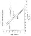
- Fig. 1 presents the calculated change in refractive index vs.
- Sylgard 184 is branches polydimethyl siloxane with some phenyl substitution available from Dow Corning.
- GE 670 is a branched polydimethyl siloxane available from General Electric.
- the refractive index of the cladding be less than the refractive index of the core.
- the refractive index of the core and the cladding are about equal, light is no longer contained by the cladding and a blackout occurs.
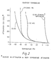
- Fig. 2 shows the blackout phenomenon for a number of commercially available siloxanes coated on a silica fiber.
- Fig. 2 presents attenuation in db vs. temperature for GE 670, Sylgard 184, and GE 655 claddings on a silica core.
- the waveguides were about 100 meters long.
- the silica core was about 200 microns in diameter and the cladding was about 20 microns thick.
- GE 655 is branches polydimethyl siloxane with some phenyl substitution.
- the data presented in Fig. 2 were obtained by measuring the attenuation of the waveguide resulting from the waveguide being cooled at 2°C/minute.
- the blackout temperatures shown for the GE 670 and Sylgard 184 clad fibers correlate approximately with the crossover points in refractive index shown in Fig. 1.
- the waveguide exhibit blackout as its temperature is raised.
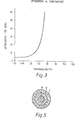
- the attenuation of such a waveguide is shown in Fig. 3, where the waveguide exhibits blackout at about,50°C. At temperatures less than about 50°C, the waveguide transmits light.
- a light absorptive material such as polymethylphenyl siloxane having an index of refraction of about 1.50 containing about 5% by weight of carbon black, and a core pf polymethylphenyl siloxane with a refractive index of 1.47 at 23°C exhibits an attenuation vs. temperature curve similar to that shown in Fig. 3.
- a disadvantage with such a waveguide is that even at temperatures at which it transmits light, the amount of attenuation is substantially more than is obtained with a waveguide with a silica core because silica has much better optical properties than polymethylphenyl siloxane.
- this disadvantage is not important where only a short waveguide is required, or where a short sensing element is incorporated such as by splicing into a long waveguide, where the remainder of the waveguide has excellent light transmission properties.
- blackout can occur at a temperature of about 25°C, provided the exterior surface of the silica tube is coated with a light absorptive material which prevents light transmission within the silica.
- Another waveguide that exhibits blackout as its temperature is increased is one having a core of polymethylphenyl siloxane containing 12% phenyl by weight, and a cladding of a Kynar copolymer such as Kynar 7200 available from Pennwalt corporation, which is a copolymer of vinylidine fluoride and tetrafluoro ethylene.
- Kynar copolymer such as Kynar 7200 available from Pennwalt corporation, which is a copolymer of vinylidine fluoride and tetrafluoro ethylene.
- One method to control the blackout temperature of a waveguide is to vary the refractive index of the cladding, the core, or both.
- the waveguide comprising a silica core and GE 655 cladding was soaked in bromonapthalene which has a refractive index of 1.61. This raised the refractive index of the cladding, which had the effect of raising the blackout temperature. As shown in Fig.
- the blackout temperature of this waveguide was raised to about 5°C.
- Other additives and dopants can be added to a cladding to either raise or lower its refractive index, depending upon the blackout' temperature desired.
- the dopant used is non-volatile so that it remains permanently in the cladding or core. Satisfactory dopants for siloxane claddings include monomeric high boiling materials which are comnpatible with the siloxane cladding.
- dopants which can be used to raise the refractive index of siloxane cladding are 2, 2-dimethyltetraphenylcyclotrisiloxane; 1,1,1,5,5, 5-hexa methyldiphenyltrisiloxane; hexaphenylcyclotri- siloxane; tetraphenylsilane; tetraphenylcyclotrisiloxane; 1,1,1,5,5,5-hexamethyldiphenyl trisiloxane; hexaphenyl- cyclotrisiloxane; tetraphenylsilane; and diallyldiphenyl- silane.
- the cladding can be irradiated to about 5 Mrads with an electron beam subsequent to imbibing in the dopant to permanently graft the dopant to the polymeric cladding.
- Other dopants can be introduced prior to the curing process. From 5 to 40 parts by weight of dopant per 100 parts by weight of polymeric cladding is usually sufficient.
- dopants are low molecular weight chlorinated phenylsiloxanes and nitrile containing siloxanes.
- Monomeric high boiling materials such as neopentylglycol- polyadipate and paraffin oils which are not siloxanes can be used as dopants in small quantities, but they suffer from the fact that they are inadequately compatible with siloxane cladding and are expelled from the cladding with time.
- Novel cladding materials developed include claddings comprising a polyalkylphenyl siloxane, where the alkyl portion of the siloxane contains no more than 10 carbon atoms, and preferably is a methyl group.
- the phenyl content is preferably at least 15% by weight; as the phenyl content of a polymethylphenyl siloxane increases, the refractive index of the siloxane increases.
- Table 1 presents the refractive index of polymethylphenyl siloxanes as a function of their phenyl content. The percent by weight phenyl is based upon the total weight of the siloxane. Also presented in Table 1 is the blackout temperature of a waveguide comprising a silica core and a polymethylphenyl siloxane cladding having the specified phenyl content. All phenyl contents referred to herein are determined by ultraviolet spectroscopy.
- Cladding materials of different phenyl content can be prepared by blending methylphenyl siloxanes with different phenyl contents.
- blends which differ widely in phenyl content tend to be milky to opaque. Therefore, when blending methylphenyl siloxanes, preferably the siloxanes differ in refractive index by no more than about 0.02 and the viscosities of both siloxanes are in the range of from about 500 to about 10,000 cps as measured at 25°C.
- methylphenyl siloxanes of different phenyl content it is also possible to cross-link methylphenyl siloxanes of different phenyl content. For example, by blending a methylphenyl siloxane having a viscosity of 2,000 cps and a phenyl content of 21% and having a terminal vinyl content of 1 mole % with a second methylphenyl siloxane having a viscosity of 2,000 cps and a phenyl content of '16%, a cladding is produced which in combination with a silica core, provides any blackout temperature required in the range of 0 to 15°C.
- a polyalkylphenyl siloxane of the desired phenyl content can be prepared according to conventional polymerization techniques, where the starting materials include dialkyl chlorosilane, diphenyl chlorosilane, and alkylphenyl chlorosilane.
- the alkyl groups can be the same or different.
- FIG.. 4 presents the attenuation vs. temperature curve for a waveguide having a silica core of 200 microns, a first cladding of KE 103 having a thickness of 30 to 35 microns, and an outer cladding layer of Sylgard 184 having a thickness of 60 microns KE 103 is a low molecular weight polydimethyl siloxane available from Shin-Etsu of Japan that crystallizes as its temperature is lowered.
- the outer layer of Sylgard is required because the KE 103 has poor mechanical properties. As shown by Fig.
- the waveguide exhibits a large and sudden increase in attenuation at about -56°C as its temperature is decreased, and also exhibits a large and sudden decrease in attenuation at about -40°C as its temperature is increased, showing a hysteresis effect.
- This large and sudden change in attenuation occurs because KE 103 is a linear, low molecular weight material and is able to crystallize. It has a differential scanning calorimeter melting point of -45°C when warmed from -120°C at 5°C per minute.
- a nucleating agent such as fumed silica can be used to prevent the freezing point from varying as a result of super cooling of the polymer liquid.
- an advantage of using a polymer that crystallizes as a cladding is that the blackout occurs over a very small temperature range.
- the waveguide can be used in applications where close control of the temperature of a material is essential.
- a material that exhibits this crystallization phenomenon preferably is sufficiently optically clear to be used as a cladding, and has a refractive index lower than that of silica.
- copolymers of dimethylsiloxane and ethylene oxide meet these requirements.
- the refractive index and crystalline melting point of the copolymer can be altered as required by varying the molar ration of the siloxane to the ethylene oxide and also by the chain length of the ethylene oxide block.
- a method for making these copolymers is described in U.S. Reissue Patent No. 25,727 which is incorporated herein by this reference.
- the copolymer prepared has a refractive index less than that of silica (about 1.46 at 23°C) so that it can be used as a cladding for silica cores.
- Particularly suitable polyethylene oxide dimethylsiloxane copolymers for water freeze protection are those whose preparation is described in Examples 1 and 2 of the 25,727 patent. These copolymers have a freezing point of 1°C and refractive indices of 1.4595 and 1.4555, respectively. These copolymers can be protected from absorbing moisture by a water resistant exterior cladding.
- Crosslinked polydialkyl siloxanes such as polydiethyl siloxane also exhibit this crystalline melting point phenomenon.
- Polyalkly diloxanes for use as a cladding comprise the repeating unit: where each R is independently selected from the group consisting of methyl, ethyl, and propyl groups; and where each R 2 is independently an alkyl group, and preferably a linear alkyl group, of at least 10 carbon atoms, and preferably no more than about 20 carbon atoms.
- the polydialkyl siloxane can be a homopolymer of polymethyldodecyl siloxane.
- it can be a copolymer of 30% by weight of polymethyldodecyl siloxane and 70% by weight polymethyltetradecyl siloxane, which has a crystalline melting point of 3°C.
- a portion of the side chains can be substituted by fluorine substituted groups such as tri-fluoropropyl.
- polymethylhexadecyl- siloxane has a melting point of 42°C, a refractive index of 1.4524 (44°C), and a freezing point of 27°C.
- Preferred materials are cross-linked polymethylalkyl siloxanes, i.e. R 1 is a methyl group.
- the polymethylalkyl siloxanes can be prepared by reacting the alkene corresponding to the alkyl portion of the siloxane with polymethylhydrogen siloxane in the presence of chloroplatinic acid catalyst. From about 80 to about 95% of the hydrogens are reacted, and at least a portion of the remaining free hydrogens are cross-linked with cross-linking agents such as tetravinyl silane in the presence of chloroplatinic acid catalyst.
- Other polydialkyl siloxanes can be correspondingly prepared using polyethylhydrogen siloxane or polypropylhydrogen siloxane.
- polymethyltetradlecyl siloxane prior to cross-linking, has a crystalline melting point of 7°C when 80% of the hydrogen is substituted with tetradecene, 12°C with 90% substitution, and 14°C with 100% substitution.
- Waveguides consisting of a cladding of cross-linked poly- methylpentadecyl siloxane on a glass core were prepared.
- the glass core used was a silica core, blackout occurred at about 5°C.
- the glass core used was made from sodium-borosilicate, blackout occurred at about -1°C.
- a waveguide used in the present invention has a core with a diameter of from about 100 to about 300 microns, and most preferably about 200 microns.
- cores of less than 100 microns it is difficult to couple and connect the waveguide.
- cores much greater than 300 microns it is possible to transmit larger amounts of light for longer distances.
- the advantages obtained are insufficient to overcome the increased material costs and breakage caused by bending.
- refractive indices mentioned herein refer to the refractive index of a material measured at a temperature of 25°C with sodium light 589 nm.
- the waveguides of the present invention are not limited to use with just visible light. They can be used with ultraviolet and infrared light.
- the term "light” as used herein refers to visible light, ultraviolet light, and infrared light.
- the cladding can be applied to the core in situ, where the cladding is cross-linked directly on the core.
- the fiber is coated before moisture or other contaminants reach the fibre.
- it is important to avoid scratching or otherwise abrading the fiber because this can drastically reduce the tensile strength of the fiber.
- it is preferred to apply a cladding with a low modulus applicator such s that described by A.C. Hart, Jr., and R.B. Albarino in "An Improved Fabrication Technique For Applying Coatings To Optical Fiber Wave Guides * , Optical Fiber Transmission II Proceedings, February 1977.
- the cladding material is applied to the fiber core as a liquid.
- the waveguide exhibits substantial change in its light transmission property at two temperatures.
- the waveguide used when providing freeze protection, it is desirable that the waveguide used exhibits substantial attenuation of transmitted light at a temperature of about 5°C, and then exhibit even more attenuation at about 1°C.
- the 5°C breakpoint can be used as a signal for turning on a heater, and the 1°C breakpoint can be used as an emergency alarm.
- a wayeguide suitable for such an application is shown in Fig. 5 and its attenuation vs. temperature curve is shown in Fig. 6.
- the waveguide of Fig. 5 comprises a core A, a first cladding B disposed on and around the exterior surface of the core, and a second cladding C disposed on and around the exterior surface of the first cladding.
- the refractive index of the first cladding B is less than the refractive index of the core A at temperatures greater than the first selected temperature T 1' and is greater than or equal to the refractive index of the core A at temperatures less than T 1 .
- the refractive index of the second cladding C is less than the refractive index of the first cladding B at temperatures greater than the second selected temperature T 2 and is greater than or equal to the refractive index of the first cladding B at termperatures less than T 2 .
- T is greater than T 2 .
- a waveguide of this construction has the attenuation vs. temperature curve as shown in Fig. 6. What occurs is that as the temperature of the waveguide is reduced to T 1 , which corresponds to about 10°C in Fig. 6, the refractive index of the first cladding becomes equal to the refractive index of the core. Thus, a portion of the transmitted light is absorbed by the cladding and the attenuation is increased. As the temperature of the waveguide is further decreased, the refractive index of the second cladding becomes equal to the refractive index of the core at T 2 , which corresponds to about 0°C in Fig. 6. At this point, blackout occurs.
- the level of attenuation that occurs at temperatures less than T 1 is at least 3 db greater than the level of attenuation at temperatures greater than T 1 .
- the level of attenuation that occurs at temperatures greater than T 2 is at least about 3 db greater than the level of atteenuation at temperatures between T and T 2 .
- the amount of attenuation that occurs at temperatures less than T 1 can be controlled by varying the thickness of the first cladding. The smaller the thickness, the less attenuation that occurs.
- the first cladding layer is thinner than the second cladding layer, and generally is on the order of about 5 microns thick vs. about 20 microns thick for the second cladding layer.
- An example of a waveguide that exhibits this two-step change in attenuation is one consisting of a silica core, a first cladding layer of cross-linked polymethylphenyl siloxane, and a second cladding of polydimethyl siloxane.
- T 1 is 14°C
- T 2 is -52°C.
- a single waveguide exhibit blackout at both ends of a selected temperature range of T 3 to T 4 .
- the attenuation vs. temperature curve of such a waveguide is shown in Fig. 7, where light is transmitted without substantial attenuation between about 10°C to about 80°C, but at about 10°C and 80°C, blackout occurs.
- a waveguide with this performance characteristic can haved the construction shown in Fig. 5., where it comprises core A of high loss material, a light transmissive layer B disposed on and around the exterior surface of the core, and an exterior cladding C disposed on and around the exterior surface of the light transmissive layer B.
- the core A is a poorer transmitter of light at temperatures lower than or equal to T 3 than is the light transmissive layer.
- the refractive index of the light transmissive layer B is greater than the refractive indices of both the core A and the exterior cladding C only at temperatures within the selected temperature range of T 3 to T 4 , T 3 being less than T 4 .
- the refractive index of the core A is greater than or equal to the refractgive index of the light transmissive layer B, so that light is no longer contained by the core A in the light transmissive layer B because the core A is made of a high loss material, light passing into the core is absorbed and blackout occurring.
- the refractive index of the exterior cladding C is greater than or equal to the refractive index of the light transmissive layer B. Because C is a less light transmissive material than B, there is an increase in attenuation at temperatures greater than T 4 .
- the change in refractive index vs. temperature for the components of a waveguide constructed in accordance with this version of the invention is shown in Fig. 8.
- These refractive index curves correspond to the attenuation curve shown in Fig. 7.
- the refractive index of the core A is less than the refractive index of the light transmissive layer B at temperatures greater than about 10°C(T 3 ).
- the refractive index of the exterior cladding C is.greater than the refractive index of the light transmissive layer B.
- a waveguide having the attenuation vs. temperature curve shown in Fig. 7 can comprise a core A made of polymethyltetradecyl siloxane, a light transmissive layer B of polymethylphenyl siloxane of 35% by weight pehnyl content, and an outer cladding C of silica coated with polymethylphenyl siloxane of more than 50% by weight phenyl content, and containing 5% by weight of carbon black.
- Another waveguide having the attenuation vs. temperature curve of Fig. 7 can be prepared where the refractive index of the core A is greater than or equal to the refractive index of the light transmissive layer B at temperatures greater than or equal to T 4 , and the refractive index of the exterior cladding C is,greater than or equal to the refractive index of the light transmissive layer B at temperatures less than or equal to T 3 .
- the core is a poorer light transmitter at temperatures greater than or equal to T 4 than is the light transmissive layer B.
- a waveguide undergoes a substantial change in its light transmission properties, that change be permanent and irreversible.
- An example of such a waveguide is one having a polyvinylidene fluoride core (available under the trade name Kynar from Pennwalt) or polymethylmethacrylate core, and a cladding of polydimethyl siloxane.
- the core is loaded with about 1% by weight of an antioxidant such as 2, 6 di-teriary butyl para-cresol.
- an antioxidant such as 2, 6 di-teriary butyl para-cresol.
- a waveguide can have portions which exhibit blackout at a selected temperature or within a selected temperature range, where the portions are separated by a portion that does not exhibit blackout at the selected temperature or within the selected temperature range. This is particularly useful when the sensing element exhibits relatively poor transmission properties even when it is operating in its mode of transmitting light.
- a single waveguide can include a plurality (two or more) sensing elements which exhibit blackout at different temperatures. For example, one sensing element can be activated at about 0°C as cooled and another sensing element can be activated at about 100°C as heated. With such a waveguide, light can be transmitted only from about 0 to about 100°C. Such a waveguide can be used as part of a system for keeping water liquid.
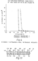
- a waveguide 30 comprising of plurality of sensing elements 32A, 32B, and 32C separated from each other by light transmitting elements 42A, 42B, and 42C is shown in Fig. 13.
- Each sensing element comprises a core 34A, 34B, -and 34C, respectively, and cladding 36A, 36B, and 36C, respectively, disposed on and around the exterior surface of the core.
- Each sensing element 32 exhibits blackout at a temperature at which the light transmitting elements 42 transmit light.
- Each light transmitting element 42A, 42B, and 42C comprises a core 44A, 44B, and 44C, respectively, and a cladding 46A, 46B, and 46C, respectively, disposed on and around the exterior surface of the core.
- the sensing'elements can have the same blackout temperature, or can have different blackout temperatures. Although the sensing elements shown in Fig. 13 are separated by light transmitting elements, sensing elements having different blackout temperatures can be adjoining.
- All the sensing elements can have the same core material or have different core materials. All the sensing elements can have the same cladding or different claddings. Likewise, the light transmitting elements can all have the same core or different cores and can all have the same cladding or different claddings. Furthermore, the cores of the light transmitting elements and the sensing elements can be the same or different. Likewise the claddings of the sensing elements and the light transmitting elements can be the same or different. However it is necessary that at least the cladding or the core of the light transmitting elements and the sensing elements be different so that the sensing elements exhibit blackout at a temperature at which the light transmitting elements transmit light.
- the light transmitting elements are substantially longer than the sensing elements.
- Each sensing element can be in the order of one to two centimeters long, while the light transmitting elements can be as long as a kilometer.
- the sensing elements 32 can be spaced every 50 feet apart, where the waveguide 30 has a total length of about a kilometer.
- Exemplary of a waveguide comprising sensing elements 32 and light transmitting elements 42 is one having a cellulose ester core (i.e. Celliodr CPHH made by Bayer A.G. anf having a refractive index of 1.470) the light transmitting element 42 having a cladding 46 of polydimethyl siloxane, and the sensing element 32 having a cladding 46 of silica with an exterior absorptive layer of methylpeheyl siloxane of 1.5 refractive index and containing 5% by weight of carbon black.
- the light transmitting elements transmit light at all temperatures in excess of -52°C.
- the sensing elements exhibit blackout at an elevated temperature of about 80°C.
- Exemplary of another waveguide comprising sensing elements 32 and light transmitting elements 42 is one having a Kynar copolymer cladding (copolymer of vinylidene fluoride and tetrafluoroethylene made by Pennwalt), a sensing element core 34 of polymethylphenylsiloxane, containing 7% phenyl by weight, and a light transmitting element core 44 of silica.
- the sensing elements blackout at about 90°C.
- the light transmitting elements transmit light up to temperatures greater than 90°C.
- Another waveguide comprising sensing elements 32 and light transmitting elements 42 has a core of cellulose -ester (of refractive index 1.47), a light transmitting element cladding 46 of polydimethyl siloxane, a first sensing element cladding 36A of silica with an exterior absorptive layer of polymethylphenyl siloxane of 1.5 refractive index and containing 5% of carbon black by weight and a second sensing element cladding 36B of polymethyltetradecyl siloxxane.
- the first sensing element 32A exhibits blackout at a temperature of about 80°C, transmitting light at temperatures less than the blackout temperature.
- the second sensing element 32B exhibits blackout at about 14°C, transmitting light at temperatures in excess of 14°C.
- the light transmitting elements 42 transmit light at temperatures greater than about -52°C.
- a method of making such a waveguide with different temperature responsive sections is to remove a portion of the cladding from the conventional waveguide and replace the removed portion of the cladding with cladding that results in the waveguide having a temperature responsive sensing element.
- a two centimeter length of the cladding can be removed from a waveguide comprising silica core and a GE670 cladding (a branched polydimethylsiloxane).
- the cladding can be removed with wire strippers, followed by removal of any residue with tetramethylguanidine, followed by a rinse with toluene and then isopropanol.
- the waveguide is maintained in-a fixed position so that bare core can be surrounded with uncured cladding which can be cured in position.
- the cladding can be a methylphenylsiloxane whose refracive index controls the blackout temperature, or a methylakylsiloxane in which the blackout temperature depends on the crystalline melting point of the cladding.
- Another method for preparing a waveguide having a short sensing element therein is to dope the cladding of a waveguide at selected locations with a dopant that alters the refractive index of the cladding.
- the new cladding can be placed inside a heat-shrinkable sleeve.
- the heat-shrinkable sleeve can be placed in position over an area of the waveguide where the cladding has been removed and then heated, thereby shrinking the sleeve.
- the coating on the inside of the sleeve can then provide a cladding - having refractive index properties that provide the waveguide with a useful sensing element.
- Another method for producing a single waveguide having one or more sensing elements along its length, where the sensing elements can exhibit a substantial change in light transmission properties at different temperatures is to pass the core through two applicators which are in tandem.
- two applicators which are in tandem.
- different claddings having different refractive index characteristics can be applied to different lengths of the core.
- the E xamnple shows how a waveguide having a blackout temperature of about 0°C for use in freeze protection can be prepared.
- a nine meter length of waveguide comprising a 200 micron fused silica core and a cladding of about 30 microns thick of polydimethylsiloxane available under the trade name GE670 was prepared. A two centimeter length of the cladding was mechanically stripped. Any residue present was removed with tetr a methylguanidien and rinsed with toluene and isopropanol. The waveguide was held in a fixed position and the uncoated fiber was surrounded with a methylphenylsiloxane solution.
- the solution consisted of 21.84% of a methylphenylsiloxane containing 15.5% phenyl by weight, 58.16% of a methylphenylsiloxane containing 20.5% phenyl by weight, and 20 % of a methylphenylsiloxane containing 7% phenyl by weight.
- the refractive index of the solution before curing was 1.4466 and after 'curing in situ in the presence 'of a chloro- platinaic acid catgalyst, the refractive index was 1.4498.
- the thickness of the new cladding was about 1/4 inch.
- the attenuation vs. temperature curve for the waveguide is presented in Fig. 9.
- a two centimeter length of the polydimethylsiloxane cladding was replaced with a siloxane composition containing 43% by weight pehnyl and having a refractive index of 1.513 before curing.
- the waveguide did not transmit light at room temperature. However, as shown in Fig. 10, at temperatures above 160°C, the waveguide did transmit light.
- This example demonstrates preparation of a waveguide that cannot transmit light at ambient temperature, but when raised to an elevated temperature, irreversibly changes so that it can transmit light, even after its temperature is reduced to ambient temperature.
- a waveguide was prepared having a core of polymethylmethacrylate having a diameter of 0.013 inch.
- the cladding was polydimethylsiloxane having a thickness of about 50 microns.
- a second waveguide was prepared, differing from the first waveguide in that it contained 1% by weight of Irganox 1010, an antioxidant available form Ciba Geigy. When light from a helium neon laser was directed through each of the waveguides, the first waveguide transmitted light along the length of 22 inches and the second waveguide transmitted light satisfactorily along a length of 28 inches as detected visually by the experimentor.
- Both fibers were irradiated with a high energy electron beam of 10 Mrads.
- the first fiber still allowed light to transmit an amount of 60% of the previous length.
- the second fiber would not allow any light to be transmitted.
- the second fiber was heated to 80°C for two hours and was then able to transmit light in an amnount of 50% of its original transmission properties, even after its temperature was reduced to ambient temperature.
- a material can be maintained within a selected temperature range. This is accomplished by placing at least part of a waveguide in thermal communication with the material so that the temperature of the part of the waveguide is responsive to the temperature of the material.
- the waveguide is selected so that it exhibits blackout at a temperature at about the top and/or at about the bottom of the selected temperature range.
- Light is directed at one end of the waveguide and the intensity of light transmitted by the part of the waveguide in thermal communication with the material is monitored. At the onset of a substantial change in the intensity of light transmitted by said part of the waveguide, the temperature of the material is adjusted so that it is within the selected range.
- Such a temperature control system can be used for many applications. For example, it can be used for over-temperature protection or for under-temperature protection of motors.
- over-temperature protection when the temperature of the motor is higher than a selected temperature, the motor is automatically shut off.
- the temperature range that is desired is all temperatures less than the temperature at which the motor is to be shut off.
- Under-temperature protection can be used to prevent a motor from being started up if the temperature is too cool for the oil to properly lubricate the motor.
- the temperature range desired is all temperatures greater than a selected temperature.
- Such a system can also be used for over temperature protection in aircraft, motor vehicles, process equipment, and the like. It can be used in automobiles for anti-freeze protection with an alarm system in case any part of a car radiator system is below a pre-determined temperature. It can be used in dams and water systems to determine when freezing is taking place. It can be used as part of a waterbed heater control system by -using a waveguide having a blackout temperature of about 90°F. It can be used during charging of batteries to prevent over heating of the battery or to prevent charing of the battery when it is too cold for safe charging.
- a temperature control system can be provided for a nickel cadmium battery because such batteries can explode if charged at temperatures less than about 0°C.
- a waveguide with a blackout temperature of at least -20°C because there are only limited applications at temperatures lower than -20°C.
- a waveguide that has a blackout temperature of -20°C can be used for detecting leaks of liquefied natural gas.
- freeze protection of aqueous solutions requires a waveguide with a blackout temperature at a temperature higher than -20°C.
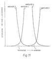
- Fig. 11 it is assumed that it is desired to keep a material within a temperature range T to T 2 .
- waveguide A or waveguide B can be used, where both of these waveguides have a blackout temperature at about T 2 .
- Waveguide A transmits light without substantial attenuation at temperatures greater than T 2
- waveguide B transmits light without substantial attenuation at temperatures less than T 2 .
- the monitor used detects a substantial increase in the intensity of light transmitted, this indicates that the material is heating to a temperature greater than T 2 , and it is necessary to cool the material.
- waveguide B if the monitor detects a substantial decrease in the light transmitted this indicates that the material is heating to a temperature greater than T 2 , and it is necessary to cool the material.
- waveguide C or waveguide D can be used, both of which have a blackout temperature at about T 1 .
- Waveguide C tansmits light without substantial attenuation at temperatures less than T 1 and waveguide D transmits light at temperatures greater than T 1 .
- the monitor determines that there is a substantial increase in the light transmitted, this indicates that the material is cooling to a temperature less than T 1 , and it is necessary to heat the material.
- waveguide D if the monitor detects a substantial decrease in the light being transmitted, this indicates that the temperature of the material cooling to a temperature less than T 1 , and it is necessary to heat the material.
- temperatures which provide sufficient time to adjust the temperature of the material to maintain it within the desired temperature range.
- a waveguide with a blackout temperature of about 5°C can be used.
- This technique could be used for preventing materials from changing phase, such as preventing water from freezing or boiling, or preventing a solid from melting or sublimating, or preventing a gas from condensing.
- a waveguide can be placed in thermal communication with the water, where the waveguide exhibits blackout at a temperature slightly above the freezing temperature of water.
- a temperature which provides sufficient time to heat the water to prevent it from freezing For example, a waveguide that transmits light at temperatures above about 5°C, and has a blackout temperature at about 5°C is suitable. Light is directed at one end of the waveguide and the intensity of light transmitted by the waveguide is monitored. At the onset of a substantial change in the intensity of the light transmitted by the waveguide, the water is heated to prevent if from freezing.
- waveguide temperature sensing systems can be used for preventing the viscosity of a liquid from changing beyond a selected value.
- a heating element such as steam tracing, electrical resistant heaters, or strip heaters comprising a conductive polymer.
- a waveguide that exhibits blackout at a temperature corresponding to the temperature at which the viscosity of the liquid increases above a selected value is placed in thermal communication with the liquid.
- the advantage of using fiber optic systems is that even if a waveguide breaks, there is no danger of an explosion and no fire hazard associated with the waveguide. This is unlike an electrical powered temperature sensing system.
- Light is directed at one end of the waveguide and the intensity of light transmitted by the waveguide is monitored. At the onset of substantial change in the intensity of light transmitted, the liquid is heated to lower its viscosity.
- the waveguide can be used for detecting leakage of a fluid from a container where the fluid is at a temperature other than ambient temperature, i.e. lower than ambient temperature or higher than ambient temperature.
- a wveguide having the attenuation vs. temperature curve of the GE 655 clad waveguide shown in Fig. 2 can be placed adjacent a container of liquid nitrogen or liquified natural gas. Light can be directed at one end of the waveguide and the other end of the waveguide can be monitored. The presence of blackout indicates that leakage of the liquid nitrogen or L N G is occurring.
- the waveguide is maintained at a temperature other than ambient temperature by a cooling or heating jacket or the like. Upon leakage of the fluid, the temperature of the jacket and waveguide changes towards ambient temperature.
- the waveguide can be selected so that as its temperature approaches ambient temperature, its light transmission properties undergo a substantial
- waveguides are not limited to detecting leakage of a fluid from a container; they can also be used as part of monitoring systems in pipelines and the like to determine where the fluid is flowing.
- a waveguide can be provided in the downstream side of each valve, so that when the valve is opened, a signal is generated indicating that fluid is passing through the valve.
- waveguides of the present invention is for detecting the level of a fluid (i.e., liquid or gas) in a container, the fluid having a temperature different from ambient temperature. This is effectged by selecting a waveguide, at least a portion of which exhibits blackout when the temperature of said portion is changed from ambient temperature to the temperature of the fluid, or a waveguide that begins to transmit light as the temperature of said portion is changed from ambient temperature to the temperature of the fluid.
- the said portion of the waveguide is placed into the container, light directed at one end of the waveguide, and the intensity of light transmitted by the portion is monitored. The onset of substantial change in the intensity of light transmitted by that portion indicates that the portion is in thermal communication with the fluid. Fluids can be measured in tanks, cargo holds, deep wells, and the like.
- Fig. 12 shows an article 10 that makes use of the present invention.
- the article comprises an outer tubular sleeve 12, which can be made of a heat-recoverable material heat activatable insert 16, and a waveguide 17 that has a blackout temperature at about the activation temperature of the heat-activatable insert 16.
- a common problem in using such articles is that the craftsmen in the field can be uncertain as to whether the entire heat-activatable material has been activated. This can be a serious problem when the heat -activatable material is a meltable material such as solder or an adhesive such as a heat-activatable adhesive or mastic which requires heat to perform its bonding and sealing functions.
- the craftsman should heat the entire article so that the entire heat-activatable insert is activated.
- the insert is within the sleeve 12
- this problem is remedied.
- the waveguide 17 is one that undergoes a change in its light transmission characteristics once it reaches a temperature at which the heat-recoverable material has recovered and the insert has been activated.
- the change is permanent and irreversible because with long articles 10, after one end of it has been heated to a desired temperature, that end can cool down to below the required temperature while the remainder of the article 10 is being heated. If a waveguide that did not undergo a permanent change were used, an operator might needlessly reheat the first end.
- the heat-activatable material can be fused material such as solder or polymeric material, an adhesive that requires heat for activation, and the like.
- the sleeve 12 can be made of a heat-recoverable or a heat-expandable material. It can be a polymeric material made from metal or other materials. Furthermore, it need not be heat recoverable at all, but only serve to hold a heat-activatable material in location until the activatable material has been activated, and then the sleeve is -ready for removal.
- the sleeve need not be continuous in cross-section, but can have a slot along its length. Likewise, the sleeve need not be circular in cros-section, but can have different shapes.
- Exemplarly of articles for which the present invention can be used are those described in U.S. Patent Nos. 3,243,211; 3,297,819; 3,305,625; 3,312,772; 3,324,230; 3,382,121; 3,415,287; 3,525,799; 3,539,411; 3,770,556; 3,847,721; 3,852,517; 3,946,143; 3,957,382; 3,988,399; 3,990,661; 3,995,964; 4,016,356, 4,045,604; 4,092,193, 4,126,759 and 4,179,320, all of which are incorporated herein by this reference.
- waveguides can be used on the leading edge of airplanes to detect icing. They can be used in cable trays in nuclear power plants to check for overheating. Therefore the spirit and scope of the appended claims should not necessarily be limited to the description of the preferred versions contained herein.
- the waveguides of the present invention can also be used for detecting fires. This is effected by placing at least part of a waveguide in a position proximate to a combustible material so that the temperature of the waveguide is higher than ambient temperature when the combustible material is on fire.
- the waveguide is chosen so that its light transmission properties exhibit a substantial change when the temperature of the waveguide is higher than ambient temperature, i.e. either the waveguide changes from a blackout condition to a light transmitting condition or the waveguide changes from a light transmitting condition to a blackout conditgion.
- Light is directed at one end of the waveguide, and the intensity of the light transmitted by the waveguide is monitored. At the onset of the substantial change, an alarm can be activated and/or a sprinkler system can be activated.
Landscapes
- Physics & Mathematics (AREA)
- General Physics & Mathematics (AREA)
- Optical Integrated Circuits (AREA)
Applications Claiming Priority (4)
| Application Number | Priority Date | Filing Date | Title |
|---|---|---|---|
| US06/136,076 US4373768A (en) | 1980-03-31 | 1980-03-31 | Thermostatic fiber optic waveguides |
| US136057 | 1980-03-31 | ||
| US06/136,057 US4417782A (en) | 1980-03-31 | 1980-03-31 | Fiber optic temperature sensing |
| US136076 | 1993-10-13 |
Publications (2)
| Publication Number | Publication Date |
|---|---|
| EP0037266A2 true EP0037266A2 (de) | 1981-10-07 |
| EP0037266A3 EP0037266A3 (de) | 1983-09-14 |
Family
ID=26833950
Family Applications (1)
| Application Number | Title | Priority Date | Filing Date |
|---|---|---|---|
| EP81301336A Withdrawn EP0037266A3 (de) | 1980-03-31 | 1981-03-27 | Verfahren und Vorrichtung zur Temperaturkontrolle oder Anzeige der Anwesenheit eines Materials mittels eines Lichtwellenleiters, Hitze-aktivierbare, Lichtleiter umfassende Artikel sowie Lichtleiter und Verfahren zur Herstellung solcher Lichtleiter |
Country Status (2)
| Country | Link |
|---|---|
| EP (1) | EP0037266A3 (de) |
| GB (6) | GB2073439B (de) |
Cited By (1)
| Publication number | Priority date | Publication date | Assignee | Title |
|---|---|---|---|---|
| EP0146522A3 (de) * | 1983-12-07 | 1986-09-17 | Monsanto Company | Polymer/optischer Sensorapparat und Verfahren |
Families Citing this family (2)
| Publication number | Priority date | Publication date | Assignee | Title |
|---|---|---|---|---|
| US4712096A (en) * | 1985-05-10 | 1987-12-08 | Firetek Corporation | Condition responsive detection system and method |
| DE3742331A1 (de) * | 1987-12-14 | 1989-06-29 | Hartmut Dr Gruhl | Verfahren zur beeinflussung der leiteigenschaften von lichtwellenleitern in abhaengigkeit von der temperatur |
Family Cites Families (5)
| Publication number | Priority date | Publication date | Assignee | Title |
|---|---|---|---|---|
| GB1175855A (en) * | 1966-08-25 | 1970-01-01 | American Optical Corp | Improvements in or relating to information processors |
| SE7808169L (sv) * | 1977-08-10 | 1979-02-11 | Graviner Ltd | Temperaturkenslig avkennare |
| GB1582768A (en) * | 1977-08-26 | 1981-01-14 | Standard Telephones Cables Ltd | Temperature sensitive optical fibre |
| US4151747A (en) * | 1978-06-21 | 1979-05-01 | Electric Power Research Institute, Inc. | Monitoring arrangement utilizing fiber optics |
| US4201446A (en) * | 1978-10-20 | 1980-05-06 | Honeywell Inc. | Fiber optic temperature sensor using liquid component fiber |
-
1981
- 1981-03-27 GB GB8109636A patent/GB2073439B/en not_active Expired
- 1981-03-27 EP EP81301336A patent/EP0037266A3/de not_active Withdrawn
-
1983
- 1983-10-24 GB GB08328381A patent/GB2141832B/en not_active Expired
- 1983-10-24 GB GB08328379A patent/GB2141831B/en not_active Expired
- 1983-10-24 GB GB08328383A patent/GB2141834B/en not_active Expired
- 1983-10-24 GB GB08328380A patent/GB2142734B/en not_active Expired
- 1983-10-24 GB GB08328382A patent/GB2141833B/en not_active Expired
Cited By (1)
| Publication number | Priority date | Publication date | Assignee | Title |
|---|---|---|---|---|
| EP0146522A3 (de) * | 1983-12-07 | 1986-09-17 | Monsanto Company | Polymer/optischer Sensorapparat und Verfahren |
Also Published As
| Publication number | Publication date |
|---|---|
| GB8328379D0 (en) | 1983-11-23 |
| GB8328380D0 (en) | 1983-11-23 |
| GB2141834A (en) | 1985-01-03 |
| GB2141831A (en) | 1985-01-03 |
| GB2141831B (en) | 1985-07-31 |
| GB2142734B (en) | 1985-07-24 |
| GB2141832B (en) | 1985-07-24 |
| GB2141834B (en) | 1985-07-24 |
| EP0037266A3 (de) | 1983-09-14 |
| GB8328381D0 (en) | 1983-11-23 |
| GB2073439B (en) | 1985-03-13 |
| GB8328383D0 (en) | 1983-11-23 |
| GB2142734A (en) | 1985-01-23 |
| GB8328382D0 (en) | 1983-11-23 |
| GB2073439A (en) | 1981-10-14 |
| GB2141833A (en) | 1985-01-03 |
| GB2141832A (en) | 1985-01-03 |
| GB2141833B (en) | 1985-07-31 |
Similar Documents
| Publication | Publication Date | Title |
|---|---|---|
| US4417782A (en) | Fiber optic temperature sensing | |
| US4505542A (en) | Thermostatic fiber optic waveguides | |
| CA1168720A (en) | Thermostatic fiber optic waveguides | |
| US4290668A (en) | Fiber optic waveguide termination and method of forming same | |
| US4334733A (en) | Coated glass fibers for optical transmission | |
| DK169368B1 (da) | Vandresistent kommunikationskabel | |
| EP2426538B1 (de) | Glasfasermodul mit verbesserter Zugänglichkeit | |
| CN101238399B (zh) | 可机械剥离的上覆光纤 | |
| FR2549970A1 (fr) | Cable a fibres optiques | |
| EP0530326A1 (de) | Isoliertes lichtwellenleiterfaserkabel mit einer polsterschicht. | |
| WO2004042447A1 (en) | Peelable buffer layer having a preferential tear portion and methods of manufacturing the same | |
| FR2564988A1 (fr) | Cable a fibres optiques | |
| BRPI0913666B1 (pt) | Fibra ótica protegida, cabo para telecomunicações, e método para a fabricação da fibra ótica protegida | |
| EP0037266A2 (de) | Verfahren und Vorrichtung zur Temperaturkontrolle oder Anzeige der Anwesenheit eines Materials mittels eines Lichtwellenleiters, Hitze-aktivierbare, Lichtleiter umfassende Artikel sowie Lichtleiter und Verfahren zur Herstellung solcher Lichtleiter | |
| WO2006073991A1 (en) | Method of preventing optical fiber failure in high power application | |
| Stolov | Aging of optical fibers in aggressive environments: Mimicking downhole and undersea applications | |
| Łakomski et al. | Determination of Brillouin backscattering strain and temperature coefficients in telecommunication optical fibers | |
| US4515474A (en) | Method and apparatus for determining peak temperature along an optical fiber | |
| EP0618465B1 (de) | Flüssigkeitsgefüllter optischer Wellenleiter | |
| EP3867676B1 (de) | Mehrschichtiges verbindungskabel mit geringer dämpfung | |
| Shuto et al. | High-temperature stability of optical transmission properties attained by liquid-crystal polymer jacket | |
| JPH01100038A (ja) | 保護光導波路 | |
| JPS6224252Y2 (de) | ||
| TOMITA et al. | 1000-fiber water-blocking cable | |
| Bark et al. | Emerging standards in fiber optic telecommunications cable |
Legal Events
| Date | Code | Title | Description |
|---|---|---|---|
| PUAI | Public reference made under article 153(3) epc to a published international application that has entered the european phase |
Free format text: ORIGINAL CODE: 0009012 |
|
| 17P | Request for examination filed |
Effective date: 19810409 |
|
| AK | Designated contracting states |
Designated state(s): AT BE CH DE FR IT NL SE |
|
| PUAL | Search report despatched |
Free format text: ORIGINAL CODE: 0009013 |
|
| AK | Designated contracting states |
Designated state(s): AT BE CH DE FR IT LI NL SE |
|
| STAA | Information on the status of an ep patent application or granted ep patent |
Free format text: STATUS: THE APPLICATION IS DEEMED TO BE WITHDRAWN |
|
| 18D | Application deemed to be withdrawn |
Effective date: 19850719 |
|
| RIN1 | Information on inventor provided before grant (corrected) |
Inventor name: SANDBERG, CHESTER LEDLIE Inventor name: CLARKE, RAYMOND |