EP0037272A1 - System zum Befestigen von Scheiben auf einer Welle - Google Patents
System zum Befestigen von Scheiben auf einer Welle Download PDFInfo
- Publication number
- EP0037272A1 EP0037272A1 EP81301348A EP81301348A EP0037272A1 EP 0037272 A1 EP0037272 A1 EP 0037272A1 EP 81301348 A EP81301348 A EP 81301348A EP 81301348 A EP81301348 A EP 81301348A EP 0037272 A1 EP0037272 A1 EP 0037272A1
- Authority
- EP
- European Patent Office
- Prior art keywords
- discs
- blade
- shaft
- face
- disc
- Prior art date
- Legal status (The legal status is an assumption and is not a legal conclusion. Google has not performed a legal analysis and makes no representation as to the accuracy of the status listed.)
- Granted
Links
Images

Classifications
-
- F—MECHANICAL ENGINEERING; LIGHTING; HEATING; WEAPONS; BLASTING
- F01—MACHINES OR ENGINES IN GENERAL; ENGINE PLANTS IN GENERAL; STEAM ENGINES
- F01D—NON-POSITIVE DISPLACEMENT MACHINES OR ENGINES, e.g. STEAM TURBINES
- F01D5/00—Blades; Blade-carrying members; Heating, heat-insulating, cooling or antivibration means on the blades or the members
- F01D5/02—Blade-carrying members, e.g. rotors
- F01D5/06—Rotors for more than one axial stage, e.g. of drum or multiple disc type; Details thereof, e.g. shafts, shaft connections
-
- F—MECHANICAL ENGINEERING; LIGHTING; HEATING; WEAPONS; BLASTING
- F01—MACHINES OR ENGINES IN GENERAL; ENGINE PLANTS IN GENERAL; STEAM ENGINES
- F01D—NON-POSITIVE DISPLACEMENT MACHINES OR ENGINES, e.g. STEAM TURBINES
- F01D5/00—Blades; Blade-carrying members; Heating, heat-insulating, cooling or antivibration means on the blades or the members
- F01D5/02—Blade-carrying members, e.g. rotors
- F01D5/025—Fixing blade carrying members on shafts
-
- F—MECHANICAL ENGINEERING; LIGHTING; HEATING; WEAPONS; BLASTING
- F01—MACHINES OR ENGINES IN GENERAL; ENGINE PLANTS IN GENERAL; STEAM ENGINES
- F01D—NON-POSITIVE DISPLACEMENT MACHINES OR ENGINES, e.g. STEAM TURBINES
- F01D5/00—Blades; Blade-carrying members; Heating, heat-insulating, cooling or antivibration means on the blades or the members
- F01D5/34—Rotor-blade aggregates of unitary construction, e.g. formed of sheet laminae
Definitions
- This invention relates to a system for keying discs to a shaft and more particularly to a system for keying blade discs to a shaft in a steam turbine.
- round keys were used and round holes were drilled at the juncture of the discs and shaft as this eliminated the sharp corners in the rectangular keyways and reduced the stress concentration; however, the area adjacent the bore of the discs have very large stresses, and the round keys still produced stress concentration, which have resulted in cracking eminating from the round keyways.
- the principal object of this invention is to eliminate any type of stress concentration in the (bore of the) discs and prevent relative movement between the discs and the shaft during periods of differential heating.
- the present invention resides in a rotor for a turbine, said rotor comprising a shaft having a plurality of circumferential steps which ascend from at least one end thereof, and a plurality of blade discs each having a bore which fits a particular circumferential step on which a respective face disc is disposed, characterized by a plurality of face discs each having a bore which fits a particular circumferential step adjacent the respective blade disc on which a respective face disc is disposed, and each face disc having a skirt adjacent its outer periphery fitted over a portion of the adjacent blade disc a plurality of inner keys disposed in inner grooves formed at the juncture of the circumferential steps and the bore of the face discs and a plurality of outer keys disposed in outer grooves formed at the juncture of the skirts and the respective portion of the blade discs for keying said blade discs to said shaft.
- a low pressure steam turbine or fluid machine 1 which comprises a casing 3 with a rotor 5 disposed therein.
- the casing 3 has journal bearings 7 disposed on opposite ends thereof for rotatably supporting the rotor 5.
- a steam inlet nozzle 9 is disposed in the central portion of the casing 3 to supply steam to circular arrays of stationary and rotatable blades 13 and 15, respectively, affixed to the casing 3 and rotor 5.
- the stationary blades 13 are disposed in blade rings or diaphragms 17 which attach to the casing 3 producing pressure stages as the steam expands through the turbine 1.
- the casing 3, journal bearings 7, and blade diaphragms 17 are split horizontally so that the upper half of the casing may be removed to permit the removal of the rotor 5.
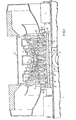
- the rotor 5 comprises a shaft 21 having a 1 lur- ality of circumferential steps 23 which ascend from each end thereof. Disposed on the circumferential steps 23 are blade discs 25 which have a central hub 27 and one or more circular arrays of rotatable blades 15 attached to their outer periphery.
- the hubs 27 each have a central bore 29 sized to fit a particular mating step 23 on the shaft 21.
- the bore 29 is normally slightly smaller than the mating step over which it slides producing interference or shrink fit therebetween.
- the hubs 27 of the blade discs 25 have a counterbore 31 and a radially extending rim or flange 33 on one end thereof, the end adjacent the next smaller diameter step.
- a face disc 35 is disposed adjacent the hub 27.
- the face disc 35 has a bore 37 which fits a mating step 23, a boss 38 adjacent the bore 37 which fits into the counterbore 31 and a skirt or lip 39 which fits over the flange 33.
- the shaft 21 and bore 37 of the face disc 35 each have aligned grooves 41 and 43, respectively, which form openings for receiving pins or keys 45 for keying the face disc 35 to the shaft 21.
- the skirts 39 and flanges 33 each have aligned grooves 47 and 49, respectively, which form openings for receiving pins or keys 51, which key the face disc 35 to the blade disc 25.
- the face disc 35 advantageously provides an intermediary member for keying the blade disc 25 to the shaft 21 and eliminating stress concentrations in the bore of the blade disc 25.
- the groove for the keys in the blade discs are disposed in an area where the tangential stress is significantly lower than that of the bore, thus reducing the possibility of stress cracks originating at the grooves.
- the keys Preferably have a round cross-section eliminating sharp corners in the keyways to further reduce stress concentrations.
Landscapes
- Engineering & Computer Science (AREA)
- Mechanical Engineering (AREA)
- General Engineering & Computer Science (AREA)
- Ceramic Engineering (AREA)
- Turbine Rotor Nozzle Sealing (AREA)
Applications Claiming Priority (2)
| Application Number | Priority Date | Filing Date | Title |
|---|---|---|---|
| US06/135,036 US4330236A (en) | 1980-03-28 | 1980-03-28 | System for keying discs to a shaft |
| US135036 | 1998-08-17 |
Publications (2)
| Publication Number | Publication Date |
|---|---|
| EP0037272A1 true EP0037272A1 (de) | 1981-10-07 |
| EP0037272B1 EP0037272B1 (de) | 1986-08-13 |
Family
ID=22466205
Family Applications (1)
| Application Number | Title | Priority Date | Filing Date |
|---|---|---|---|
| EP81301348A Expired EP0037272B1 (de) | 1980-03-28 | 1981-03-27 | System zum Befestigen von Scheiben auf einer Welle |
Country Status (10)
| Country | Link |
|---|---|
| US (1) | US4330236A (de) |
| EP (1) | EP0037272B1 (de) |
| JP (1) | JPS5848727B2 (de) |
| KR (1) | KR840002219B1 (de) |
| BR (1) | BR8101778A (de) |
| CA (1) | CA1140054A (de) |
| DE (1) | DE3175096D1 (de) |
| ES (1) | ES500767A0 (de) |
| MX (1) | MX151928A (de) |
| ZA (1) | ZA811091B (de) |
Cited By (1)
| Publication number | Priority date | Publication date | Assignee | Title |
|---|---|---|---|---|
| FR2499148A1 (fr) * | 1981-01-30 | 1982-08-06 | Westinghouse Electric Corp | Systeme pour claveter des roues a aubes sur un arbre |
Families Citing this family (7)
| Publication number | Priority date | Publication date | Assignee | Title |
|---|---|---|---|---|
| GB2108628B (en) * | 1981-10-28 | 1985-04-03 | Rolls Royce | Means for reducing stress in clamped assemblies |
| US4509900A (en) * | 1982-10-14 | 1985-04-09 | Tokyo Shibaura Denki Kabushiki Kaisha | Turbine rotor |
| US4497612A (en) * | 1983-11-25 | 1985-02-05 | General Electric Company | Steam turbine wheel antirotation means |
| US4602411A (en) * | 1984-01-13 | 1986-07-29 | Westinghouse Electric Corp. | Method for fabricating a rotor disc assembly |
| US4537560A (en) * | 1984-05-29 | 1985-08-27 | General Electric Company | Radial key for steam turbine wheels |
| US4682934A (en) * | 1985-12-06 | 1987-07-28 | General Electric Company | Wheel anti-rotation means |
| RU2282038C2 (ru) * | 2004-01-08 | 2006-08-20 | Открытое акционерное общество "Силовые машины-ЗТЛ, ЛМЗ, Электросила, Энергомашэкспорт" (ОАО "Силовые машины") | Ротор паровой турбины |
Citations (7)
| Publication number | Priority date | Publication date | Assignee | Title |
|---|---|---|---|---|
| DE328282C (de) * | 1919-07-22 | 1920-10-27 | Adam Heinrich Boehm | Radnabe fuer Dampf- und Gasturbinen mit hoher Umfangsgeschwindigkeit |
| US1873956A (en) * | 1930-05-05 | 1932-08-30 | Allis Chalmers Mfg Co | Rotor structure |
| US2441432A (en) * | 1945-12-14 | 1948-05-11 | Gen Electric | High-speed rotor |
| DE854604C (de) * | 1943-06-16 | 1952-11-06 | Maschf Augsburg Nuernberg Ag | Laufrad fuer axialdurchstroemte Kreiselradmaschinen, insbesondere Gasturbinen |
| US2807434A (en) * | 1952-04-22 | 1957-09-24 | Gen Motors Corp | Turbine rotor assembly |
| GB906361A (en) * | 1960-04-09 | 1962-09-19 | Daimler Benz Ag | Improvements relating to the rotors of flow machines |
| FR2295226A1 (fr) * | 1974-12-16 | 1976-07-16 | Europ Turb Vapeur | Dispositif de clavetage entre disques d'une turbine |
Family Cites Families (7)
| Publication number | Priority date | Publication date | Assignee | Title |
|---|---|---|---|---|
| US1593393A (en) * | 1923-10-30 | 1926-07-20 | Gen Electric | Elastic-fluid turbine and the like |
| FR648174A (fr) * | 1927-06-11 | 1928-12-06 | Rateau Sa | Dispositif pour compenser la dilatation des rotors de turbines à vapeur |
| BE510277A (de) * | 1951-03-30 | |||
| US3304052A (en) * | 1965-03-30 | 1967-02-14 | Westinghouse Electric Corp | Rotor structure for an elastic fluid utilizing machine |
| US3822953A (en) * | 1972-11-07 | 1974-07-09 | Westinghouse Electric Corp | Disc retainer device |
| CH590414A5 (de) * | 1975-07-04 | 1977-08-15 | Bbc Brown Boveri & Cie | |
| DE2643886C2 (de) * | 1976-09-29 | 1978-02-09 | Kraftwerk Union AG, 4330 Mülheim | Gasturbinentäufer in Scheibenbauart |
-
1980
- 1980-03-28 US US06/135,036 patent/US4330236A/en not_active Expired - Lifetime
-
1981
- 1981-02-18 ZA ZA00811091A patent/ZA811091B/xx unknown
- 1981-03-09 CA CA000372585A patent/CA1140054A/en not_active Expired
- 1981-03-13 MX MX186363A patent/MX151928A/es unknown
- 1981-03-25 BR BR8101778A patent/BR8101778A/pt unknown
- 1981-03-27 DE DE8181301348T patent/DE3175096D1/de not_active Expired
- 1981-03-27 ES ES500767A patent/ES500767A0/es active Granted
- 1981-03-27 KR KR1019810001009A patent/KR840002219B1/ko not_active Expired
- 1981-03-27 JP JP56044252A patent/JPS5848727B2/ja not_active Expired
- 1981-03-27 EP EP81301348A patent/EP0037272B1/de not_active Expired
Patent Citations (7)
| Publication number | Priority date | Publication date | Assignee | Title |
|---|---|---|---|---|
| DE328282C (de) * | 1919-07-22 | 1920-10-27 | Adam Heinrich Boehm | Radnabe fuer Dampf- und Gasturbinen mit hoher Umfangsgeschwindigkeit |
| US1873956A (en) * | 1930-05-05 | 1932-08-30 | Allis Chalmers Mfg Co | Rotor structure |
| DE854604C (de) * | 1943-06-16 | 1952-11-06 | Maschf Augsburg Nuernberg Ag | Laufrad fuer axialdurchstroemte Kreiselradmaschinen, insbesondere Gasturbinen |
| US2441432A (en) * | 1945-12-14 | 1948-05-11 | Gen Electric | High-speed rotor |
| US2807434A (en) * | 1952-04-22 | 1957-09-24 | Gen Motors Corp | Turbine rotor assembly |
| GB906361A (en) * | 1960-04-09 | 1962-09-19 | Daimler Benz Ag | Improvements relating to the rotors of flow machines |
| FR2295226A1 (fr) * | 1974-12-16 | 1976-07-16 | Europ Turb Vapeur | Dispositif de clavetage entre disques d'une turbine |
Cited By (1)
| Publication number | Priority date | Publication date | Assignee | Title |
|---|---|---|---|---|
| FR2499148A1 (fr) * | 1981-01-30 | 1982-08-06 | Westinghouse Electric Corp | Systeme pour claveter des roues a aubes sur un arbre |
Also Published As
| Publication number | Publication date |
|---|---|
| US4330236A (en) | 1982-05-18 |
| MX151928A (es) | 1985-05-03 |
| CA1140054A (en) | 1983-01-25 |
| ZA811091B (en) | 1982-03-31 |
| KR830005462A (ko) | 1983-08-13 |
| ES8300930A1 (es) | 1982-11-01 |
| EP0037272B1 (de) | 1986-08-13 |
| BR8101778A (pt) | 1981-09-29 |
| KR840002219B1 (ko) | 1984-12-03 |
| JPS5848727B2 (ja) | 1983-10-31 |
| ES500767A0 (es) | 1982-11-01 |
| JPS56151201A (en) | 1981-11-24 |
| DE3175096D1 (en) | 1986-09-18 |
Similar Documents
| Publication | Publication Date | Title |
|---|---|---|
| US2356605A (en) | Turbine rotor | |
| US4415310A (en) | System for cooling a gas turbine by bleeding air from the compressor | |
| US5018941A (en) | Blade fixing arrangement for a turbomachine rotor | |
| EP0037272A1 (de) | System zum Befestigen von Scheiben auf einer Welle | |
| EP0821133B1 (de) | Befestigung von Bläserschaufeln bei einem Gasturbinentriebwerk | |
| US4465429A (en) | Steam turbine with superheated blade disc cavities | |
| US3702222A (en) | Rotor blade structure | |
| CA1162458A (en) | Rotor for a hydroelectric machine | |
| US3184153A (en) | Rotor construction | |
| US4425077A (en) | Turbine disc environment control system | |
| US3623826A (en) | Turbine pump with improved rotor and seal constructions | |
| US3294027A (en) | Centrifugal pump impeller | |
| KR930008675B1 (ko) | 증기 터어빈용 블레이드 링 | |
| GB848465A (en) | Rotors of multi-stage axial flow compressors or turbines | |
| KR890001168B1 (ko) | 탄성 유체 기계용 로우터 | |
| US2786625A (en) | Turbo-machines | |
| DE3461001D1 (en) | Rotor for radial turbines | |
| JPS59136501A (ja) | タ−ビンロ−タ | |
| SU1152308A1 (ru) | Способ изготовления лопаточного диска турбомолекулярного насоса | |
| GB897415A (en) | Improvements in or relating to bladed rotors | |
| CN206694075U (zh) | 一种汽轮机无叶片叶轮、转子及多通道汽轮机 | |
| US4045099A (en) | Rotor for a turbo-machine | |
| SU1177433A1 (ru) | Многоступенчата турбина турбобура | |
| RU2001104063A (ru) | Центробежный насос | |
| CA1206886A (en) | Blade platform with seal land |
Legal Events
| Date | Code | Title | Description |
|---|---|---|---|
| PUAI | Public reference made under article 153(3) epc to a published international application that has entered the european phase |
Free format text: ORIGINAL CODE: 0009012 |
|
| AK | Designated contracting states |
Designated state(s): DE FR GB IT |
|
| 17P | Request for examination filed |
Effective date: 19820323 |
|
| ITF | It: translation for a ep patent filed | ||
| GRAA | (expected) grant |
Free format text: ORIGINAL CODE: 0009210 |
|
| AK | Designated contracting states |
Kind code of ref document: B1 Designated state(s): DE FR GB IT |
|
| REF | Corresponds to: |
Ref document number: 3175096 Country of ref document: DE Date of ref document: 19860918 |
|
| ET | Fr: translation filed | ||
| PLBE | No opposition filed within time limit |
Free format text: ORIGINAL CODE: 0009261 |
|
| STAA | Information on the status of an ep patent application or granted ep patent |
Free format text: STATUS: NO OPPOSITION FILED WITHIN TIME LIMIT |
|
| 26N | No opposition filed | ||
| PGFP | Annual fee paid to national office [announced via postgrant information from national office to epo] |
Ref country code: FR Payment date: 19901218 Year of fee payment: 11 |
|
| PGFP | Annual fee paid to national office [announced via postgrant information from national office to epo] |
Ref country code: GB Payment date: 19901227 Year of fee payment: 11 |
|
| PGFP | Annual fee paid to national office [announced via postgrant information from national office to epo] |
Ref country code: DE Payment date: 19910330 Year of fee payment: 11 |
|
| ITTA | It: last paid annual fee | ||
| PG25 | Lapsed in a contracting state [announced via postgrant information from national office to epo] |
Ref country code: GB Effective date: 19920327 |
|
| GBPC | Gb: european patent ceased through non-payment of renewal fee | ||
| PG25 | Lapsed in a contracting state [announced via postgrant information from national office to epo] |
Ref country code: FR Effective date: 19921130 |
|
| PG25 | Lapsed in a contracting state [announced via postgrant information from national office to epo] |
Ref country code: DE Effective date: 19921201 |
|
| REG | Reference to a national code |
Ref country code: FR Ref legal event code: ST |