EP0037399B1 - Schlösser - Google Patents
Schlösser Download PDFInfo
- Publication number
- EP0037399B1 EP0037399B1 EP80901115A EP80901115A EP0037399B1 EP 0037399 B1 EP0037399 B1 EP 0037399B1 EP 80901115 A EP80901115 A EP 80901115A EP 80901115 A EP80901115 A EP 80901115A EP 0037399 B1 EP0037399 B1 EP 0037399B1
- Authority
- EP
- European Patent Office
- Prior art keywords
- lock
- handle
- key
- cylinder
- rod
- Prior art date
- Legal status (The legal status is an assumption and is not a legal conclusion. Google has not performed a legal analysis and makes no representation as to the accuracy of the status listed.)
- Expired
Links
- 230000008878 coupling Effects 0.000 claims abstract description 8
- 238000010168 coupling process Methods 0.000 claims abstract description 8
- 238000005859 coupling reaction Methods 0.000 claims abstract description 8
- 230000007246 mechanism Effects 0.000 claims description 11
- 230000037431 insertion Effects 0.000 claims 1
- 238000003780 insertion Methods 0.000 claims 1
- 241000220317 Rosa Species 0.000 abstract description 11
- 238000006073 displacement reaction Methods 0.000 abstract 1
- 230000008901 benefit Effects 0.000 description 3
- 230000009471 action Effects 0.000 description 2
- 230000006835 compression Effects 0.000 description 2
- 238000007906 compression Methods 0.000 description 2
- 238000000034 method Methods 0.000 description 2
- 206010052805 Drug tolerance decreased Diseases 0.000 description 1
- 230000000712 assembly Effects 0.000 description 1
- 238000000429 assembly Methods 0.000 description 1
- KULDXINYXFTXMO-UHFFFAOYSA-N bis(2-chloroethyl) (3-chloro-4-methyl-2-oxochromen-7-yl) phosphate Chemical compound C1=C(OP(=O)(OCCCl)OCCCl)C=CC2=C1OC(=O)C(Cl)=C2C KULDXINYXFTXMO-UHFFFAOYSA-N 0.000 description 1
- 238000011161 development Methods 0.000 description 1
- 230000018109 developmental process Effects 0.000 description 1
- 230000006872 improvement Effects 0.000 description 1
- 238000009434 installation Methods 0.000 description 1
- 230000003993 interaction Effects 0.000 description 1
- 230000007935 neutral effect Effects 0.000 description 1
- 229910000679 solder Inorganic materials 0.000 description 1
Images


Classifications
-
- E—FIXED CONSTRUCTIONS
- E05—LOCKS; KEYS; WINDOW OR DOOR FITTINGS; SAFES
- E05B—LOCKS; ACCESSORIES THEREFOR; HANDCUFFS
- E05B35/00—Locks for use with special keys or a plurality of keys ; keys therefor
- E05B35/007—Locks for use with special keys or a plurality of keys ; keys therefor the key being a card, e.g. perforated, or the like
-
- E—FIXED CONSTRUCTIONS
- E05—LOCKS; KEYS; WINDOW OR DOOR FITTINGS; SAFES
- E05B—LOCKS; ACCESSORIES THEREFOR; HANDCUFFS
- E05B13/00—Devices preventing the key or the handle or both from being used
- E05B13/005—Disconnecting the handle
-
- Y—GENERAL TAGGING OF NEW TECHNOLOGICAL DEVELOPMENTS; GENERAL TAGGING OF CROSS-SECTIONAL TECHNOLOGIES SPANNING OVER SEVERAL SECTIONS OF THE IPC; TECHNICAL SUBJECTS COVERED BY FORMER USPC CROSS-REFERENCE ART COLLECTIONS [XRACs] AND DIGESTS
- Y10—TECHNICAL SUBJECTS COVERED BY FORMER USPC
- Y10T—TECHNICAL SUBJECTS COVERED BY FORMER US CLASSIFICATION
- Y10T70/00—Locks
- Y10T70/50—Special application
- Y10T70/5611—For control and machine elements
- Y10T70/5757—Handle, handwheel or knob
- Y10T70/5765—Rotary or swinging
- Y10T70/5805—Freely movable when locked
- Y10T70/5819—Handle-carried key lock
- Y10T70/5823—Coaxial clutch connection
- Y10T70/5827—Axially movable clutch
-
- Y—GENERAL TAGGING OF NEW TECHNOLOGICAL DEVELOPMENTS; GENERAL TAGGING OF CROSS-SECTIONAL TECHNOLOGIES SPANNING OVER SEVERAL SECTIONS OF THE IPC; TECHNICAL SUBJECTS COVERED BY FORMER USPC CROSS-REFERENCE ART COLLECTIONS [XRACs] AND DIGESTS
- Y10—TECHNICAL SUBJECTS COVERED BY FORMER USPC
- Y10T—TECHNICAL SUBJECTS COVERED BY FORMER US CLASSIFICATION
- Y10T70/00—Locks
- Y10T70/70—Operating mechanism
- Y10T70/7441—Key
- Y10T70/7486—Single key
- Y10T70/7497—Tumblerless warded
-
- Y—GENERAL TAGGING OF NEW TECHNOLOGICAL DEVELOPMENTS; GENERAL TAGGING OF CROSS-SECTIONAL TECHNOLOGIES SPANNING OVER SEVERAL SECTIONS OF THE IPC; TECHNICAL SUBJECTS COVERED BY FORMER USPC CROSS-REFERENCE ART COLLECTIONS [XRACs] AND DIGESTS
- Y10—TECHNICAL SUBJECTS COVERED BY FORMER USPC
- Y10T—TECHNICAL SUBJECTS COVERED BY FORMER US CLASSIFICATION
- Y10T70/00—Locks
- Y10T70/70—Operating mechanism
- Y10T70/7441—Key
- Y10T70/7486—Single key
- Y10T70/7503—Tumbler and ward type
-
- Y—GENERAL TAGGING OF NEW TECHNOLOGICAL DEVELOPMENTS; GENERAL TAGGING OF CROSS-SECTIONAL TECHNOLOGIES SPANNING OVER SEVERAL SECTIONS OF THE IPC; TECHNICAL SUBJECTS COVERED BY FORMER USPC CROSS-REFERENCE ART COLLECTIONS [XRACs] AND DIGESTS
- Y10—TECHNICAL SUBJECTS COVERED BY FORMER USPC
- Y10T—TECHNICAL SUBJECTS COVERED BY FORMER US CLASSIFICATION
- Y10T70/00—Locks
- Y10T70/70—Operating mechanism
- Y10T70/7441—Key
- Y10T70/7486—Single key
- Y10T70/7508—Tumbler type
- Y10T70/7559—Cylinder type
- Y10T70/7576—Sliding and rotary plug
-
- Y—GENERAL TAGGING OF NEW TECHNOLOGICAL DEVELOPMENTS; GENERAL TAGGING OF CROSS-SECTIONAL TECHNOLOGIES SPANNING OVER SEVERAL SECTIONS OF THE IPC; TECHNICAL SUBJECTS COVERED BY FORMER USPC CROSS-REFERENCE ART COLLECTIONS [XRACs] AND DIGESTS
- Y10—TECHNICAL SUBJECTS COVERED BY FORMER USPC
- Y10T—TECHNICAL SUBJECTS COVERED BY FORMER US CLASSIFICATION
- Y10T70/00—Locks
- Y10T70/70—Operating mechanism
- Y10T70/7441—Key
- Y10T70/7486—Single key
- Y10T70/7508—Tumbler type
- Y10T70/7559—Cylinder type
- Y10T70/7588—Rotary plug
- Y10T70/7593—Sliding tumblers
-
- Y—GENERAL TAGGING OF NEW TECHNOLOGICAL DEVELOPMENTS; GENERAL TAGGING OF CROSS-SECTIONAL TECHNOLOGIES SPANNING OVER SEVERAL SECTIONS OF THE IPC; TECHNICAL SUBJECTS COVERED BY FORMER USPC CROSS-REFERENCE ART COLLECTIONS [XRACs] AND DIGESTS
- Y10—TECHNICAL SUBJECTS COVERED BY FORMER USPC
- Y10T—TECHNICAL SUBJECTS COVERED BY FORMER US CLASSIFICATION
- Y10T70/00—Locks
- Y10T70/70—Operating mechanism
- Y10T70/7441—Key
- Y10T70/7729—Permutation
-
- Y—GENERAL TAGGING OF NEW TECHNOLOGICAL DEVELOPMENTS; GENERAL TAGGING OF CROSS-SECTIONAL TECHNOLOGIES SPANNING OVER SEVERAL SECTIONS OF THE IPC; TECHNICAL SUBJECTS COVERED BY FORMER USPC CROSS-REFERENCE ART COLLECTIONS [XRACs] AND DIGESTS
- Y10—TECHNICAL SUBJECTS COVERED BY FORMER USPC
- Y10T—TECHNICAL SUBJECTS COVERED BY FORMER US CLASSIFICATION
- Y10T70/00—Locks
- Y10T70/70—Operating mechanism
- Y10T70/7441—Key
- Y10T70/778—Operating elements
- Y10T70/7791—Keys
- Y10T70/7881—Bitting
- Y10T70/7893—Permutation
Definitions
- the present invention relates to locks and particularly to locks adapted for a wide variety of applications providing domestic door locks, high level security locks with or without cooperating timing devices, motor vehicle ignition locks and the like.
- Lock mechanisms have been proposed which are operated by apertured card keys and U.S. Patent 4.111.018 discloses one such proposal.
- the card key is inserted into a slot provided in the turn knob and coacts with tumblers to place the ends of the tumblers on a shear line between two relatively movable parts of the lock assembly.
- the tumblers locate within respective apertures of the card key so as to be correctly positioned and in that respect the apertures operate very much as the bittings of a conventional key.
- the turn knob can be rotated as required to operate a latch for example.
- the tumbers are not so arranged however, one of the aforementioned relatively movable parts is positioned to prevent proper rotation of the turn knob and cannot be moved from that position because of interaction with the tumblers.
- the lock assembly of the type indicated in the prior art portion of claim 1 (known from U.S. Patent 4,111,018) is an improvement over conventional pin tumbler locks in that the key is more difficult to duplicate. On the other hand, the lock is susceptible to forced operation and consequently is not appropriate for high security applications.
- a lock according to the invention includes a lock body securable to a door or the like, a lock cylinder rotatably mounted in said lock body and held against axial movement relative thereto, a latch actuating member which is rotatably movable, a handle rotatably mounted on said lock body and provided with an opening; a key blade which is provided with at least one ward aperture therethrough, the said key blade being insertable into said opening, so that a ward member enters said ward aperture, characterised in that said handle is also movable relative to said lock body in the direction of its rotational axis, an opening is provided in a side of said handle, at least one ward member is secured within said lock body to be held against relative movement in the axial direction of said handle, releasable coupling means is operable to drivably connect said lock cylinder to said actuating member, actuating means is movably mounted in said lock body for movement from a rest position to an actu
- the locking member is biased towards said rest position.
- a handle 10 having a cylindrical neck 11 adapted to be axially movable into and away from a collar 12 of a door rose 13.
- the rose 13 is positioned within a suitable circular recess in a door (not shown) such that the shoulder 14 of the rose bears against the face of the door.
- Figs. 1 and 2 clearly illustrate this, and emphasise a major advantage of this invention in that the lock mechanism is substantially within the door and not within the handle as is the case with the prior art. This of course adds to the security of the lock.
- the rose 13 is secured to the door by means of bolts (not shown) passing through the door from the other side and engaging the rose in threaded recesses, one of which is shown at 60.
- the collar 12 is provided with an internal flange 15 which comprises the upper limiting means for a main compression spring 16, the other end of which bears against a flange 17 of the lock casing 18.
- the lock casing is secured to the handle 10 by three bolts 19 and is biassed away from same by said spring 16.
- the outer casing 18 is axially movable within said rose 13, and is constrained by a first circlip 20 engaged in an annular groove 21 in the lock casing best shown in Figs. 1 or 2.
- the lock mechanism comprising the crux of this invention is housed within the casing 18 and is prevented from rotating therein by three rods 22 secured in an inner collar 23.
- the rods 22 allow axial movement of the lock mechanism by sliding within bores 57 provided in the casing 18 best shown in Figures 1 or 2.
- the inner collar 23 is secured within the outer casing 18 by a second circlip 24 engaged in a second annular groove 25 in the outer casing 18.
- the lock cylinder 26 which is provided with a number of fixed rods 29 coaxial with the lock assembly.
- the lock cylinder is secured against rotation or axial movement within the inner collar by a grub screw 27 which is tightened against a shoulder 28 of the cylinder. Hence the cylinder and inner collar may rotate within the outer casing but are restrained axially.
- the fixed rods 29 are preferably of equal length, and protrude to a level just below the rim of the outer collar 12. These fixed rods may vary in diameter, shape, number and location in the lock cylinder 26.
- the inner collar/cylinder, outer casing and outer collar deliberately make a loose fit one within the other, although the components within cylinder 26 are fitted with decreased tolerances. The reason for the variation in tolerances will be explained more fully below.
- An inner cylinder 30 having any desired combination of fixed rods 31 and sliding rods 32 protruding therefrom is provided eccentrically within the upper portion of said outer cylinder 26, such that the said rods also protrude into the neck of the rose collar to a distance approximately the same as the fixed rods 29 but eccentrically with respect to same.
- the sliding rods 32 are located within bores 33 and their upper ends are provided with shoulders 34. Removal of the sliding rods is also prevented by deformities in the lower ends of the rods as shown in Figs. 1 or 2.
- the locking member is provided within said inner case 30, and in this embodiment comprises a brush 36 loosely mounted on a rod 37.
- a sleeve 38 having a shoulder 39 on the lower side thereof and castellations 40 on the upper face thereof.
- the sleeve is affixed to the inner cylinder 30 by any suitable means, such as silver solder or threaded engagement. It is obviously important the sleeve be rotated with respect to the inner cylinder before it is affixed to same, in order that the same degree of eccentricity is achieved. This is desirable to ensure the axis of the locking member is parallel to the axis of the lock.
- An internal flange 41 is provided on the inner sides of the sleeve 38, as seen in Figs. 1 and 2. Said sleeve is secured against rotation or axial movement within the lock cylinder by any suitable means such as a cup head bolt 42.
- a connecting member 43 which is biassed over rod 37 and against locking member 36 by a compression spring 44 which in turn is restrained by a bar 45 through a hole in the inner end of the locking member 43 and the flange 41.
- the inner end of the connecting member is bored out at 59 to accommodate rod 37.
- the operative end of the connecting member 43 is shaped into a square rod at 47 to engage a square hole 58 in any known latch withdrawal mechanism shown generally at 48 in Figs. 1 and 2.
- the hole in this sleeve through which the locking member passes is eccentric in relation to the cylinder by approximately 0.05 inches.
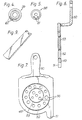
- the key as shown in Figs. 6 and 7 comprises a flat frame 49 to which is attached a handle 50.
- the frame is made unidirectional by a tongue 51, and is provided with two rotatable tokens 52, 53 one within the other.
- This inner token 53 is eccentric within the outer token 52 provides greater number of combinations and thus greater security.
- Each token is provided with holes 56, which may be varied in number size and location from key to key to suit the variations on the cylinders. In an unillustrated variation the key may be more acceptable to the consumer by the provision of a handle that folds into the same plane as the frame.
- the inner face of the neck 11 of the handle 10 is provided with a shallow recess 54 for receiving the key when offered up to the handle in a radial direction. Further, the side of the neck 11 is recessed at 55 to accommodate the key handle 50 on release of the door handle 10 and axial movement of the key within the collar 12. This will now be fully described.
- the following relates to the installation of the lock in an exterior door handle, and in most cases is matched with a normal direct acting handle on the inside of the door.
- the handle is biassed towards the door by spring 16, but may be axially withdrawn so that a key may be radially inserted into recess 54 on the inner face of the handle neck 11.
- the key must be fully inserted to allow the legs of the handle to fit into recess 55.
- the handle may be released, causing the key to be axially carried onto the rods 29, 30 and 32.
- the key is held by the base of the neck 11 on one side, recesses 54 and 55, and the upper end of the casing 18 on the other side.
- the handle, casing and key axially and rotationally move together in relation to the'lock cylinder, inner casing and sleeve.
- cup head bolt 42 be tight, ensuring no slippage between the sleeve and the cylinder.
- Other methods of securing these components form part of the invention, as does equivalent methods of securing the cylinder to the collar 23 other than by the grub screw 27.
- two movable rods 32 are used. This provides a protection against the unauthorised depression of one rod 31, as the bush, which is a loose fit on rod 37, would then become misaligned due to the uneven pressure and lock on rod 37. Friction means such as the provision of thread on rod 37 may be used to enhance such locking action. The immobilisation of the bush thus prevents movement of the connecting member.
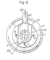
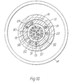
- a major advantage of our invention is found in the ability to reset the tokens within the key. Either one or both tokens may be reset. Should it be desired to rotate the inner token in relation to the outer token and the key frame, the key is inserted in the door in the normal way. The inner handle assembly (which is not subject to security measures) and the outer handle assembly are removed, exposing the inner face of the lock assembly. The cup head bolt is loosened, and an adjustment tool (Fig. 9) is fitted to the holes 61 in the sleeve and the whole rotated as desired. See Figs. 4 and 5. This action causes the pins 31, 32 to rotate with respect to pins 29, and hence the inner token relative to the outer in the key. The bolt 42 is then re-tightened.
- the grub screw 27 is loosened, and the tool applied to holes 62 in the collar 23. Rotation of the collar within the casing 18, which holds the key via the handle recess, achieves the desired result.
- a second lock may be fitted to the inner handle, in which case the inner coller (not shown) of the rose of the second lock would be lengthened and expanded to project further through the door to engage and slide over the collar 63 of the first rose.
- transverse holes are provided through the overlapping collars and long expanding bolts of the Luxon type used from the edge of the door to lock the two collars, and hence the two lock assemblies, together.
- the inner handle may be provided with a snib to prevent the locking member engaging.
- the inner handle may be provided with a snib to prevent the locking member engaging.
Landscapes
- Lock And Its Accessories (AREA)
- Switch Cases, Indication, And Locking (AREA)
- Acyclic And Carbocyclic Compounds In Medicinal Compositions (AREA)
- Burglar Alarm Systems (AREA)
- Mobile Radio Communication Systems (AREA)
- Pharmaceuticals Containing Other Organic And Inorganic Compounds (AREA)
- Vehicle Step Arrangements And Article Storage (AREA)
- Supporting Of Heads In Record-Carrier Devices (AREA)
- Air Bags (AREA)
- Transition And Organic Metals Composition Catalysts For Addition Polymerization (AREA)
- Seal Device For Vehicle (AREA)
- Feeding And Controlling Fuel (AREA)
- Endoscopes (AREA)
- Slide Fasteners (AREA)
Claims (18)
Applications Claiming Priority (2)
| Application Number | Priority Date | Filing Date | Title |
|---|---|---|---|
| AU9271/79 | 1979-06-20 | ||
| AUPD927179 | 1979-06-20 |
Publications (3)
| Publication Number | Publication Date |
|---|---|
| EP0037399A4 EP0037399A4 (de) | 1981-10-13 |
| EP0037399A1 EP0037399A1 (de) | 1981-10-14 |
| EP0037399B1 true EP0037399B1 (de) | 1985-01-16 |
Family
ID=3768146
Family Applications (1)
| Application Number | Title | Priority Date | Filing Date |
|---|---|---|---|
| EP80901115A Expired EP0037399B1 (de) | 1979-06-20 | 1980-12-30 | Schlösser |
Country Status (13)
| Country | Link |
|---|---|
| US (1) | US4448050A (de) |
| EP (1) | EP0037399B1 (de) |
| AT (1) | ATE11316T1 (de) |
| DE (1) | DE3069965D1 (de) |
| DK (1) | DK75681A (de) |
| ES (1) | ES8102617A1 (de) |
| FI (1) | FI801985A7 (de) |
| IT (1) | IT1131360B (de) |
| NO (1) | NO810488L (de) |
| NZ (1) | NZ194063A (de) |
| PH (1) | PH21717A (de) |
| PT (1) | PT71416A (de) |
| WO (1) | WO1980002857A1 (de) |
Families Citing this family (7)
| Publication number | Priority date | Publication date | Assignee | Title |
|---|---|---|---|---|
| ES289551Y (es) * | 1985-10-11 | 1986-12-01 | Fernandez Sanz Angel | Herradura para instalaciones hoteleras y similares |
| FR2589926B1 (fr) * | 1985-11-14 | 1993-12-31 | Neiman Sa | Verrou a pistons a rotor coulissant embrayable avec un organe de commande |
| SE465473B (sv) * | 1990-01-26 | 1991-09-16 | Ferenc Moricz | Uppbrytningssaekra laas, speciellt foer bilar |
| DE4122414C1 (de) * | 1991-07-06 | 1992-12-03 | Huelsbeck & Fuerst | Schließzylinder |
| US6543264B2 (en) * | 2001-07-30 | 2003-04-08 | Harrow Products, Inc. | Mortise lockset with internal clutch having override feature |
| US20090293563A1 (en) * | 2008-05-28 | 2009-12-03 | Bing-Huei Jeng | Lock with multiply circled cylinder |
| CN209761036U (zh) * | 2018-12-19 | 2019-12-10 | 弋鹤鸣 | 一种针孔式锁体结构及可变换锁匙结构 |
Family Cites Families (32)
| Publication number | Priority date | Publication date | Assignee | Title |
|---|---|---|---|---|
| US3125A (en) * | 1843-06-09 | Am phdtoxlltho c c | ||
| US474519A (en) * | 1892-05-10 | candee | ||
| US1302933A (en) * | 1919-05-06 | Valve-lock | ||
| US2238942A (en) * | 1941-04-22 | Lock for lock controlled alarms | ||
| US757265A (en) * | 1903-01-16 | 1904-04-12 | John Smalley Campbell | Lock. |
| US817713A (en) * | 1904-02-18 | 1906-04-10 | William H Hope | Door lock and latch. |
| US1505571A (en) * | 1922-05-19 | 1924-08-19 | Luoma John | Adjustable-tumbler key lock |
| US1720838A (en) * | 1923-03-05 | 1929-07-16 | Juan De Castro Y Plans | Combination lock and key |
| US1772790A (en) * | 1925-12-21 | 1930-08-12 | James M Weaver | Lock |
| US1855697A (en) * | 1929-04-22 | 1932-04-26 | Studebaker Corp | Door latch |
| FR794791A (fr) * | 1931-03-11 | 1936-02-25 | Verrou à pompe | |
| US1867650A (en) * | 1931-05-15 | 1932-07-19 | Arthur W Bryan | Gasoline tank cap lock |
| FR746946A (fr) * | 1932-09-14 | 1933-06-08 | Serrure à combinaisons | |
| US2322040A (en) * | 1941-04-25 | 1943-06-15 | Maruri Jesus Palazuelos | Handle and latch operating device |
| FR921676A (fr) * | 1946-01-17 | 1947-05-14 | Dispositif anti-vol pour véhicules automobiles | |
| US2704934A (en) * | 1951-01-22 | 1955-03-29 | Nilsson Fabian | Key controlled tumbler lock |
| US2683977A (en) * | 1953-01-12 | 1954-07-20 | Frederick M Mace | Combination and key controlled lock |
| US2919739A (en) * | 1958-11-06 | 1960-01-05 | Bernard J Vocke | Wheel cover lock |
| US3455128A (en) * | 1966-01-03 | 1969-07-15 | Emil Tenkoff | Tumbler construction and lock using the same |
| US3505841A (en) * | 1968-08-12 | 1970-04-14 | Perennial Products Inc | Combination lock |
| FR2131031A5 (de) * | 1971-03-30 | 1972-11-10 | Sepm | |
| DE2058802C3 (de) * | 1970-11-30 | 1980-02-28 | Neiman & Co Kg, 5600 Wuppertal | Lenkschloß für Kraftfahrzeuge |
| FR2197403A5 (de) * | 1973-05-16 | 1974-03-22 | Aubert Andre | |
| CH573534A5 (en) * | 1973-11-09 | 1976-03-15 | Schlage Lock Co | Binary cylinder for door locks - has pin swivel mounted in cylinder forming key guide and implements forming openings |
| CH578670A5 (en) * | 1974-01-07 | 1976-08-13 | Goal Kk | Electric cylinder type lock - has solenoid with locking piece to plunger point, and is guide groove supported |
| US3916656A (en) * | 1974-07-01 | 1975-11-04 | Schlage Lock Co | Secret latch |
| US3995460A (en) * | 1975-05-30 | 1976-12-07 | Sedley Bruce S | Magnetic card key operated door lock structure |
| US4006615A (en) * | 1975-08-07 | 1977-02-08 | Janos Szova | Axial tumbler lock |
| US4133194A (en) * | 1976-12-02 | 1979-01-09 | Bruce S. Sedley | Magnetic key operated door lock |
| CA1011571A (en) * | 1976-12-06 | 1977-06-07 | Aksel Pilvet | Key operated lock |
| GB1541483A (en) * | 1977-05-31 | 1979-03-07 | Cave O S | Locks |
| US5420272A (en) * | 1992-08-13 | 1995-05-30 | American Cyanamid Company | 7-(substituted)-8-(substituted)-9-](substituted glycyl)amido]-6-demethyl-6-deoxytetracyclines |
-
1980
- 1980-06-16 NZ NZ194063A patent/NZ194063A/xx unknown
- 1980-06-18 IT IT8022880A patent/IT1131360B/it active
- 1980-06-18 DE DE8080901115T patent/DE3069965D1/de not_active Expired
- 1980-06-18 WO PCT/AU1980/000023 patent/WO1980002857A1/en not_active Ceased
- 1980-06-18 US US06/237,133 patent/US4448050A/en not_active Expired - Lifetime
- 1980-06-18 AT AT80901115T patent/ATE11316T1/de not_active IP Right Cessation
- 1980-06-19 PH PH24168A patent/PH21717A/en unknown
- 1980-06-19 FI FI801985A patent/FI801985A7/fi not_active Application Discontinuation
- 1980-06-19 PT PT71416A patent/PT71416A/pt unknown
- 1980-06-20 ES ES80493093A patent/ES8102617A1/es not_active Expired
- 1980-12-30 EP EP80901115A patent/EP0037399B1/de not_active Expired
-
1981
- 1981-02-12 NO NO810488A patent/NO810488L/no unknown
- 1981-02-20 DK DK75681A patent/DK75681A/da unknown
Also Published As
| Publication number | Publication date |
|---|---|
| ATE11316T1 (de) | 1985-02-15 |
| US4448050A (en) | 1984-05-15 |
| EP0037399A4 (de) | 1981-10-13 |
| ES493093A0 (es) | 1981-02-16 |
| NO810488L (no) | 1981-02-12 |
| DK75681A (da) | 1981-02-20 |
| EP0037399A1 (de) | 1981-10-14 |
| DE3069965D1 (en) | 1985-02-28 |
| NZ194063A (en) | 1984-09-28 |
| IT1131360B (it) | 1986-06-18 |
| WO1980002857A1 (en) | 1980-12-24 |
| IT8022880A0 (it) | 1980-06-18 |
| ES8102617A1 (es) | 1981-02-16 |
| PH21717A (en) | 1988-02-03 |
| PT71416A (en) | 1980-07-01 |
| FI801985A7 (fi) | 1981-01-01 |
Similar Documents
| Publication | Publication Date | Title |
|---|---|---|
| USRE39364E1 (en) | Cylinder lock and key | |
| US4434636A (en) | Lock having a cylinder core and a housing | |
| US5010753A (en) | Interchangeable core lock | |
| US3999413A (en) | Lock assembly | |
| US3599455A (en) | Tumbler lock | |
| US5133203A (en) | Axial pin tumbler lock | |
| US5079936A (en) | High security cylinder lock | |
| US4195502A (en) | Break-away door knob | |
| US6539758B2 (en) | Push-button steering wheel lock | |
| US5229747A (en) | Tamperproof lock | |
| NZ527010A (en) | High strength lever handle lock mechanism | |
| GB2210405A (en) | Improved cylinder lock and key | |
| WO1998006916A1 (en) | Axial moving pushbutton for a lock having rotary locking and release motions | |
| US5617750A (en) | Pin tumbler locks and keys therefor | |
| EP1121502A1 (de) | Zylinderschloss mit einbruchssicherung | |
| US5070715A (en) | Interchangeable lock core cylinder | |
| US3316742A (en) | Locks | |
| US4342478A (en) | Knob-connector spring | |
| US4621510A (en) | Axial pin tubular lock with improved punch-out security | |
| EP0037399B1 (de) | Schlösser | |
| EP0978608A1 (de) | Zylinderschlossmechanismus | |
| US3952562A (en) | Combined knob and permutation lock assembly for door latches | |
| EP0556505B1 (de) | Schloss mit axial angeordneten Stiftzuhaltungen | |
| US4580425A (en) | High security lock | |
| US2031155A (en) | Lock |
Legal Events
| Date | Code | Title | Description |
|---|---|---|---|
| PUAI | Public reference made under article 153(3) epc to a published international application that has entered the european phase |
Free format text: ORIGINAL CODE: 0009012 |
|
| 17P | Request for examination filed |
Effective date: 19810716 |
|
| AK | Designated contracting states |
Designated state(s): AT CH DE FR GB LI NL SE |
|
| GRAA | (expected) grant |
Free format text: ORIGINAL CODE: 0009210 |
|
| AK | Designated contracting states |
Designated state(s): AT CH DE FR GB LI NL SE |
|
| PG25 | Lapsed in a contracting state [announced via postgrant information from national office to epo] |
Ref country code: SE Effective date: 19850116 Ref country code: NL Effective date: 19850116 Ref country code: LI Effective date: 19850116 Ref country code: FR Free format text: THE PATENT HAS BEEN ANNULLED BY A DECISION OF A NATIONAL AUTHORITY Effective date: 19850116 Ref country code: CH Effective date: 19850116 Ref country code: AT Effective date: 19850116 |
|
| REF | Corresponds to: |
Ref document number: 11316 Country of ref document: AT Date of ref document: 19850215 Kind code of ref document: T |
|
| REF | Corresponds to: |
Ref document number: 3069965 Country of ref document: DE Date of ref document: 19850228 |
|
| REG | Reference to a national code |
Ref country code: CH Ref legal event code: PL |
|
| NLV1 | Nl: lapsed or annulled due to failure to fulfill the requirements of art. 29p and 29m of the patents act | ||
| EN | Fr: translation not filed | ||
| PLBE | No opposition filed within time limit |
Free format text: ORIGINAL CODE: 0009261 |
|
| STAA | Information on the status of an ep patent application or granted ep patent |
Free format text: STATUS: NO OPPOSITION FILED WITHIN TIME LIMIT |
|
| 26N | No opposition filed | ||
| PG25 | Lapsed in a contracting state [announced via postgrant information from national office to epo] |
Ref country code: GB Effective date: 19880618 |
|
| GBPC | Gb: european patent ceased through non-payment of renewal fee | ||
| PG25 | Lapsed in a contracting state [announced via postgrant information from national office to epo] |
Ref country code: DE Effective date: 19890301 |