EP0037565A2 - Système de commande pour freins commandés pour fluide avec une commande de freinage automatique - Google Patents
Système de commande pour freins commandés pour fluide avec une commande de freinage automatique Download PDFInfo
- Publication number
- EP0037565A2 EP0037565A2 EP81102509A EP81102509A EP0037565A2 EP 0037565 A2 EP0037565 A2 EP 0037565A2 EP 81102509 A EP81102509 A EP 81102509A EP 81102509 A EP81102509 A EP 81102509A EP 0037565 A2 EP0037565 A2 EP 0037565A2
- Authority
- EP
- European Patent Office
- Prior art keywords
- controller
- control
- brake
- control device
- pid controller
- Prior art date
- Legal status (The legal status is an assumption and is not a legal conclusion. Google has not performed a legal analysis and makes no representation as to the accuracy of the status listed.)
- Granted
Links
- 230000001133 acceleration Effects 0.000 claims abstract description 25
- 230000007423 decrease Effects 0.000 claims description 5
- 230000000694 effects Effects 0.000 claims 3
- 239000013642 negative control Substances 0.000 claims 1
- 239000013641 positive control Substances 0.000 claims 1
- 230000002123 temporal effect Effects 0.000 claims 1
- 230000003137 locomotive effect Effects 0.000 description 11
- 230000007246 mechanism Effects 0.000 description 8
- 230000008859 change Effects 0.000 description 4
- 230000005284 excitation Effects 0.000 description 4
- 238000012986 modification Methods 0.000 description 3
- 230000004048 modification Effects 0.000 description 3
- 230000001105 regulatory effect Effects 0.000 description 3
- 238000004804 winding Methods 0.000 description 3
- 230000008901 benefit Effects 0.000 description 2
- 230000001934 delay Effects 0.000 description 2
- 108010074506 Transfer Factor Proteins 0.000 description 1
- 238000013459 approach Methods 0.000 description 1
- 230000002238 attenuated effect Effects 0.000 description 1
- 230000033228 biological regulation Effects 0.000 description 1
- 230000005540 biological transmission Effects 0.000 description 1
- 238000012937 correction Methods 0.000 description 1
- 238000013016 damping Methods 0.000 description 1
- 230000001419 dependent effect Effects 0.000 description 1
- 238000013461 design Methods 0.000 description 1
- 238000011161 development Methods 0.000 description 1
- 230000018109 developmental process Effects 0.000 description 1
- 238000010586 diagram Methods 0.000 description 1
- 230000004044 response Effects 0.000 description 1
- 230000003068 static effect Effects 0.000 description 1
- 238000012546 transfer Methods 0.000 description 1
Images
Classifications
-
- B—PERFORMING OPERATIONS; TRANSPORTING
- B60—VEHICLES IN GENERAL
- B60T—VEHICLE BRAKE CONTROL SYSTEMS OR PARTS THEREOF; BRAKE CONTROL SYSTEMS OR PARTS THEREOF, IN GENERAL; ARRANGEMENT OF BRAKING ELEMENTS ON VEHICLES IN GENERAL; PORTABLE DEVICES FOR PREVENTING UNWANTED MOVEMENT OF VEHICLES; VEHICLE MODIFICATIONS TO FACILITATE COOLING OF BRAKES
- B60T13/00—Transmitting braking action from initiating means to ultimate brake actuator with power assistance or drive; Brake systems incorporating such transmitting means, e.g. air-pressure brake systems
- B60T13/10—Transmitting braking action from initiating means to ultimate brake actuator with power assistance or drive; Brake systems incorporating such transmitting means, e.g. air-pressure brake systems with fluid assistance, drive, or release
- B60T13/66—Electrical control in fluid-pressure brake systems
- B60T13/665—Electrical control in fluid-pressure brake systems the systems being specially adapted for transferring two or more command signals, e.g. railway systems
-
- B—PERFORMING OPERATIONS; TRANSPORTING
- B60—VEHICLES IN GENERAL
- B60T—VEHICLE BRAKE CONTROL SYSTEMS OR PARTS THEREOF; BRAKE CONTROL SYSTEMS OR PARTS THEREOF, IN GENERAL; ARRANGEMENT OF BRAKING ELEMENTS ON VEHICLES IN GENERAL; PORTABLE DEVICES FOR PREVENTING UNWANTED MOVEMENT OF VEHICLES; VEHICLE MODIFICATIONS TO FACILITATE COOLING OF BRAKES
- B60T8/00—Arrangements for adjusting wheel-braking force to meet varying vehicular or ground-surface conditions, e.g. limiting or varying distribution of braking force
- B60T8/17—Using electrical or electronic regulation means to control braking
- B60T8/1701—Braking or traction control means specially adapted for particular types of vehicles
- B60T8/1705—Braking or traction control means specially adapted for particular types of vehicles for rail vehicles
-
- B—PERFORMING OPERATIONS; TRANSPORTING
- B60—VEHICLES IN GENERAL
- B60L—PROPULSION OF ELECTRICALLY-PROPELLED VEHICLES; SUPPLYING ELECTRIC POWER FOR AUXILIARY EQUIPMENT OF ELECTRICALLY-PROPELLED VEHICLES; ELECTRODYNAMIC BRAKE SYSTEMS FOR VEHICLES IN GENERAL; MAGNETIC SUSPENSION OR LEVITATION FOR VEHICLES; MONITORING OPERATING VARIABLES OF ELECTRICALLY-PROPELLED VEHICLES; ELECTRIC SAFETY DEVICES FOR ELECTRICALLY-PROPELLED VEHICLES
- B60L2200/00—Type of vehicles
- B60L2200/26—Rail vehicles
-
- Y—GENERAL TAGGING OF NEW TECHNOLOGICAL DEVELOPMENTS; GENERAL TAGGING OF CROSS-SECTIONAL TECHNOLOGIES SPANNING OVER SEVERAL SECTIONS OF THE IPC; TECHNICAL SUBJECTS COVERED BY FORMER USPC CROSS-REFERENCE ART COLLECTIONS [XRACs] AND DIGESTS
- Y02—TECHNOLOGIES OR APPLICATIONS FOR MITIGATION OR ADAPTATION AGAINST CLIMATE CHANGE
- Y02T—CLIMATE CHANGE MITIGATION TECHNOLOGIES RELATED TO TRANSPORTATION
- Y02T10/00—Road transport of goods or passengers
- Y02T10/60—Other road transportation technologies with climate change mitigation effect
- Y02T10/72—Electric energy management in electromobility
Definitions
- the invention relates to a control device for pressure-controlled brakes of vehicles, in particular track-bound vehicles.
- the locomotive in particular for trains with a purely pneumatic train brake, the locomotive usually has a generator brake and a pneumatic supplementary brake.
- the train brake is controlled via a conventional pneumatic train control line.
- the AFB regulates the speed and acceleration of the train by regulating the drive and by operating the locomotive and train brakes.
- Separate controllers are provided for the two brakes (cf. magazine "Electric Railways", 1972, Issue 7, page 155).
- the controller for the electric brake (e-brake) does not cause any major difficulties, since the e-brake reacts to a control signal relatively precisely and without a particular time delay.
- the pneumatic train brake (P-brake) prepares against this Difficulties due to considerable time delays, especially due to the pneumatic train control line.
- Delay regulation of freight trains causes considerable problems as a result.
- the object of the present invention is to design the controllers for braking force or deceleration control in such a way that the problems described above are overcome, i.e. that the influence of time delays of the pneumatic brake is reduced when controlled by electrical regulators.
- a proportional-integral-differential controller that is supplemented or modified in various points is used as the controller for the deceleration or acceleration control.
- the deceleration controller receives its setpoint signal b soll from a speed controller and its actual value signal b is from a differentiator, the input of which is supplied with a signal proportional to the train speed.
- a modification of the PID controller is that its integral part is limited by a limiter in its time rise or fall.
- the dynamic pressure of a pneumatic brake is characterized by the maximum pressure change rate, which is specified by the control valve. Even if the pressure in the main air changes suddenly The brake cylinder pressure therefore runs with a fixed gradient, since the control valve works approximately as a three-point regulator.
- the maximum rate of change of the integral part of the controller signal is limited in order to avoid excessive leading of the integral part and thus also the manipulated variable compared to the controlled variable in the event of large control deviations. It is important that the rate of change of the entire controller output signal is not limited, but that of the integral component, since otherwise the proportional component of the PID controller would also be affected, which would lead to unnecessary delay in the brake response.
- a simple implementation for limiting the rate of change of the integral component is that the input signal of the integrator is limited for positive as well as negative values.
- the limitation for positive and negative signals can be of different sizes, so that, for example, a stronger limitation acts in the direction of releasing than in the direction of braking.
- this limitation can depend on the type of train, e.g. whether it is a freight train or a passenger train, or on other train data, such as the length of the train.
- a realization that supplies the different limiting thresholds for positive and negative signals changes the limited integrator input signal depending on the sign of the system deviation by means of a switch which switches the limited signal over a Multiplier leads or leads directly to the 'input of the integrator.
- Another modification of the PID controller is that the initial value of the integral component when the PID controller responds is set to a value that corresponds to the current setpoint of the braking request at the time the PID controller responds.
- the control system When the brake is switched on for the first time, the control system must be ineffective, since the acceleration pressure of the control valves causes the brake pressure to jump to a value that is independent of the specified control variable. Since the brake almost does not react to the control variable in this initial phase, the PID controller is deactivated until a starting value is reached. This start-up value is reached after a predetermined time, after which the PID controller is activated. In order to avoid a jump in the controller output variable compared to the previously reached pickup value, the initial value of the integrator of the PID controller is set to this pickup value, so that pressure and controller state match when the controller is used. Without this measure, the integral component would be zero, and the controller would immediately reduce the pressure if there was no additional control deviation.
- Another modification of the PID controller is that its D component is only effective when the absolute value of the control deviation decreases.
- the D component is thus used as a damping element.
- the D component in a control system is used to increase or spark the dynamics of the control system.
- the control variable eg control pressure of the driver's brake valve
- the differentiator of the PID controller only becomes effective when the absolute value of the control deviation decreases, so that the setpoint and actual value of the controlled variable approach each other. On the other hand, the differentiator does not work if the absolute value of the control deviation increases.
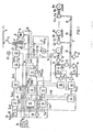
- a traction motor 1 is connected on the armature side to the contact wire 4 via a transformer 2 provided with winding taps and a pantograph 3 attached to the traction vehicle.
- the excitation winding 6 is connected to earth during driving placed.
- the switch 5 is switched so that the armature circuit of the traction motor 1 is closed via the braking resistor 7 and the excitation converter 8, which is fed by the transformer 2, is connected to the excitation winding 6.
- the traction motor 1 acts on drive wheels 9, on which a speedometer-10 is attached.
- a main air line 11 is laid in a known manner through the train, to which a pressure cylinder 15, which acts on the brake pads 16, is connected via control valves 12, in the locomotive via a double check valve 13, a pressure intensifier 14.
- a direct control of the pressure intensifier 14 takes place via a control solenoid valve 17 and the double check valve 13, specifically as a compressed air supplementary brake.
- a control solenoid valve 18 is provided, which influences the pressure of the main air line 11 via a relay valve 19.
- the main air ducts of the cars attached to the locomotive are connected at 20.
- control valves 12.1 to 12.n are connected to the main air line. These act on brake cylinders 15.1 to 15.n, which transmit their power to the brake pads 16.1 to 16.n and brake the wheels 9.1 to 9.n.
- the transformer 2 is tapped by a switching mechanism 21 which can be actuated by a driving switch 23 via a switching mechanism control 22.
- the switching mechanism 22 is controlled by a traction controller 24 via the lines "switching mechanism up” and “switching mechanism down".
- the target value Z is to get the tension controller 24 from an acceleration controller 25 for driving and the actual value of Yes from the converter 26.
- the acceleration controller 25 for driving receives a set point A to from a speed regulator 27 and an acceleration value are of a differentiator 28, which the actual velocity V of the tachogenerator 10 is differentiated.
- the speed controller 27 for driving operation receives its setpoint V soll from a speed setpoint generator 29.
- the actual speed V ist is fed to the tachometer machine 10 to an actual value input.
- the speed controller 27 is influenced by the control logic 30 via a “drive” enable input.
- the brake exciter rectifier 8 is controlled by a braking torque controller 31 via the control line ⁇ st.
- the setpoint for the braking torque controller 31 is obtained in an acceleration controller 32 for the electric brake.
- the braking torque controller 31 receives an additional setpoint ZMB from a constant value connection device 33.
- the actual values for the braking torque controller 31 Yes for the armature current and Je for the excitation current are obtained in the converters 26 and 34.
- the braking torque actual value MB is obtained in the braking torque controller 31 is fed to the constant value connection device 33.
- this device receives a signal 33 from a setter 34 'that determines the train mass added by the train driver, and a signal .DELTA.v which in a difference former 35 to from the target speed V and the actual velocity V is formed.
- the signal from the adjuster 34 is also fed to the control logic 30.
- the pneumatic train brake and the supplementary brake of the locomotive are activated.
- the brake controller 36 for the supplementary brake receives the setpoint MBE soll from the acceleration controller 32 and the actual value of the electric brake MB is from the braking torque controller 31.
- the output signal of the brake controller 36 for the supplementary brake is fed via an amplifier 37 to the control solenoid valve 17, which. controls the auxiliary brake of the locomotive.
- the delay controller 32 receives as inputs the value A to a speed regulator 38 for the braking operation and the Beuggungsistwert A is selected from the differentiator 28.
- the speed regulator 38 for the braking operation is obtained on the one hand as a target value the speed value V soll from the speed sensor 29 and the actual velocity V of the speedometer machine 10. Another input of the speed controller 38 for the braking operation comes from the control logic 30 and enables the braking operation.
- the pneumatic brake of the train is - as described above - influenced by the main air line 11.
- the control of the main air line 11 takes place in manual operation via the driver's brake valve 39, which is provided with a hand lever 40, or in automatic operation via the relay valve 19 and the control solenoid valve 18.
- This control solenoid valve 18 is controlled via an amplifier 41 and the brake force regulator 42 for the pneumatic brake operation .
- the braking force controller 42 for the compressed air brake receives the setpoint value C V soll from the deceleration controller 43 for the train brake, which is also fed to the control logic 30.
- the actual value CV ist is obtained from the pilot brake cylinder pressure of the control valve 12 of the locomotive.
- the deceleration controller 43 for the train brake receives its input values like the deceleration controller 32 for the electric brake from the differentiator 28 and the speed controller 38 for the braking operation. Delay controller 43 also receives an enable signal from control logic 30.
- the control logic 30 obtains from the signals supplied to it, among other things. also a signal Br for the driving brake changer 5, which switches the electrical equipment of the locomotive from driving to braking.
- the control logic 30 also receives the signal SWO from the switching mechanism control 22, which signals the zero position of the switching mechanism.
- the converter control is controlled by the traction controller 24.
- the acceleration controllers 25 for "driving” and the acceleration controllers for "braking”, as well as the deceleration controllers 32 for electric braking and deceleration controllers 43 for pneumatic braking of the train are designed separately in order to optimally coordinate the dynamic behavior of the individual circuits to be able to.
- the control logic 30 takes over the simultaneous actuation of the acceleration controllers 32 and 43 according to a predetermined function for the optimal distribution of the braking forces between the electric and pneumatic brakes.
- control logic can be activated in parallel.
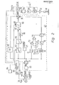
- FIG. 2 shows a more detailed illustration of the regulator for the pneumatic train brake shown in FIG. 1.
- the signal V ist is differentiated in the differentiator 28 and is supplied to the acceleration controller 43 as the actual value signal of the acceleration.
- the setpoint signal for the speed comes from the speed setpoint generator 29 and is also fed to the speed controller 38.
- the signals b should and are fed to a difference generator 60 which feeds the control deviation signal of the acceleration A b via a controlled switch 61 to the P, I and D components of the PID controller.
- the proportional branch of the controller contains a proportional amplifier 62 with the gain factor VR.
- the integral branch of the controller contains a limiter 63, to which the signal db is fed.
- the output of the limiter 63 can be connected either directly to an adder 67 via a changeover switch 64 or to the adder 67 via a multiplier 66.
- the multiplier 66 multiplies its input signal by a factor VP.
- the switch 64 is controlled as a function of the sign of the control deviation, db.
- the signal ⁇ b becomes unity Sign determiner 65 supplied, the output of which is connected to the control input of the changeover switch 64.
- the output of the adder 67 is connected to an integrator 68, the output of which is connected to a terminal of an adder 78.
- An initial value connection of the integrator 68 is connected to a start value transmitter 83, which will be explained further below.
- the differential branch of the controller contains a differentiator 70, to which the signal ⁇ b is fed.
- a sign determiner 72 is also provided, to which the signal Ab is also fed.
- the output signal of the differentiator 70 is fed to a further sign determiner 71.
- the outputs of the two sign determiners are each fed to two inputs of a NOR gate 73 and an AND gate 74.
- the outputs of the two gates 73 and 74 are fed to an OR gate 75, the output of which is connected to a control input of a switch 77.
- the output of the differentiator 70 is connected to a limiter 76, the output of which is connected to the input of the switch 77.
- the output of switch 77 is connected to one terminal of adder 78.
- the output of the proportional amplifier 62 is also connected to an input of the adder 78.
- the output of the adder 78 supplies the controller output signal CV soll , which is fed to the braking force controller 42.
- the braking force controller 42 contains a difference generator 79, to which the signal CV is intended , a signal for the starting behavior CV is intended , and the signal C V ist (in a modified form) is supplied.
- the signal CV is in a multiplier 80 by a factor VF multiplied.
- the output of the difference former is connected to a proportional amplifier 81, the output of which in turn is connected to a limiter 82.
- the output of the limiter 82 is fed to the amplifier 41, the output variable of which controls the control solenoid valve 18.
- a jump value transmitter 83 is also provided, which emits a time-limited signal CV solla for the jump behavior when a first braking force is requested .
- the start value transmitter 83 switches off and at this moment generates a control signal which closes the switch 61 so that the controller 43 is used.
- a value corresponding to the light-off value at the time the switch 61 is closed is supplied by the light-up value transmitter 83 to the initial value input 69 of the integrator 68.
- a train type actuator 84 is also provided, with which the threshold values of the limiter 83 can be set.
- the switch 61 is closed after the time period which is predetermined in the start value transmitter 83.
- the control deviation signal A b is fed to the P, I and D branches of the controller 43. It is limited in the limiter 63, as a result of which the rise and fall speed of the output signal of the integrator 68 is also limited.
- the integrator 68 is supplied depending on the requirement for braking or releasing the deviation signal directly or attenuated (multiplier 66). This integrator then integrates from the initial value applied to its connection 69 and outputs the integral component of the signal CVsoll .
- the signal ⁇ b is differentiated and limited in the D branch of the controller.
- Logic 71 to 75 ensures that the D branch only emits an output signal when the absolute value of the control deviation decreases.
- the switch 77 is opened when the control deviation ⁇ b and the time deviation of the control deviation have the same sign.
- the gain of the controlled system can be derived from the driver's brake valve and the control valve of the locomotive fluctuate only within relatively narrow limits. It is therefore proposed to form the proportional portion of the braking force controller with the actual value falsified by a factor VF. In this way, if the dynamics are neglected, with a proportional gain VR and the distance gain VS, the following transfer function between the setpoint and actual value is obtained: respectively
- Oversteer e.g. in driver's brake valves
- the pilot pressure of the driver's brake valve is dynamically limited in the direction of the brakes, but not in the direction of releasing.
- Another advantage is that additional correction elements in the form of an integral part can be kept low, since these parts can only intervene with a relatively large time delay.
- Deviations in the path gain VS which must be known approximately, from the assumed value by a factor K are dependent on the variable VR by the controller. VS weakened. The transmission factor is falsified by the factor K
Landscapes
- Engineering & Computer Science (AREA)
- Transportation (AREA)
- Mechanical Engineering (AREA)
- Braking Systems And Boosters (AREA)
- Regulating Braking Force (AREA)
- Electric Propulsion And Braking For Vehicles (AREA)
- Braking Arrangements (AREA)
Priority Applications (1)
| Application Number | Priority Date | Filing Date | Title |
|---|---|---|---|
| AT81102509T ATE20859T1 (de) | 1980-04-03 | 1981-04-03 | Regeleinrichtung fuer druckmittelgesteuerte bremsen von fahrzeugen mit automatischer bremssteuerung. |
Applications Claiming Priority (2)
| Application Number | Priority Date | Filing Date | Title |
|---|---|---|---|
| DE3013197A DE3013197C2 (de) | 1980-04-03 | 1980-04-03 | Automatische Fahr-Bremssteuerung für spurgebundene Fahrzeuge |
| DE3013197 | 1980-04-03 |
Publications (3)
| Publication Number | Publication Date |
|---|---|
| EP0037565A2 true EP0037565A2 (fr) | 1981-10-14 |
| EP0037565A3 EP0037565A3 (en) | 1984-10-24 |
| EP0037565B1 EP0037565B1 (fr) | 1986-07-23 |
Family
ID=6099320
Family Applications (1)
| Application Number | Title | Priority Date | Filing Date |
|---|---|---|---|
| EP81102509A Expired EP0037565B1 (fr) | 1980-04-03 | 1981-04-03 | Système de commande pour freins commandés pour fluide avec une commande de freinage automatique |
Country Status (4)
| Country | Link |
|---|---|
| EP (1) | EP0037565B1 (fr) |
| JP (1) | JPS5730657A (fr) |
| AT (1) | ATE20859T1 (fr) |
| DE (2) | DE3013197C2 (fr) |
Cited By (7)
| Publication number | Priority date | Publication date | Assignee | Title |
|---|---|---|---|---|
| EP0037564A3 (en) * | 1980-04-03 | 1984-10-24 | Siemens Aktiengesellschaft | Automatic drive-brake control system |
| EP0152300A3 (en) * | 1984-02-13 | 1986-12-10 | Westinghouse Brake And Signal Company Limited | Brake control system |
| WO1991012160A3 (fr) * | 1990-02-16 | 1991-10-31 | Bloxwich Eng | Commande des forces de freinage dans des combinaisons tracteur-remorque |
| US5691896A (en) * | 1995-08-15 | 1997-11-25 | Rosemount, Inc. | Field based process control system with auto-tuning |
| US5812428A (en) * | 1995-09-22 | 1998-09-22 | Rosemount Inc. | Process controller having non-integrating control function and adaptive bias |
| US5818714A (en) * | 1996-08-01 | 1998-10-06 | Rosemount, Inc. | Process control system with asymptotic auto-tuning |
| EP1808348A1 (fr) * | 2006-01-12 | 2007-07-18 | Knorr-Bremse Systeme für Schienenfahrzeuge GmbH | Réglage de pression précise et sans usure à l'aide de soupapes de commande destinées au réglage de la pression des freins dans des véhicules sur rails |
Families Citing this family (1)
| Publication number | Priority date | Publication date | Assignee | Title |
|---|---|---|---|---|
| DE102019212179A1 (de) * | 2019-08-14 | 2021-02-18 | Siemens Mobility GmbH | Verfahren zur Geschwindigkeitsregelung eines Schienenfahrzeugs |
Family Cites Families (1)
| Publication number | Priority date | Publication date | Assignee | Title |
|---|---|---|---|---|
| DE6608396U (de) * | 1965-04-15 | 1971-08-05 | Siemens Ag | Bremseinrichtung fuer schienenfahrzeuge. |
-
1980
- 1980-04-03 DE DE3013197A patent/DE3013197C2/de not_active Expired
-
1981
- 1981-04-03 AT AT81102509T patent/ATE20859T1/de not_active IP Right Cessation
- 1981-04-03 EP EP81102509A patent/EP0037565B1/fr not_active Expired
- 1981-04-03 DE DE8181102509T patent/DE3174965D1/de not_active Expired
- 1981-04-03 JP JP5045281A patent/JPS5730657A/ja active Pending
Non-Patent Citations (2)
| Title |
|---|
| EISENBAHNTECHNISCHE RUNDSCHAU, Band 29, November 1980, Seiten 775-779, Darmstadt, DE; K.-J. GOTTHARDT: "Einsatz von Mikrocomputern auf Triebfahrzeugen" * |
| SIEMENS ZEITSCHRIFT, Nr. 6, Juni 1965, Seiten 595-600, Erlangen, DE; A. ASSMUS: "Fahr- und Bremssteuerung der Lokomotive E 03" * |
Cited By (8)
| Publication number | Priority date | Publication date | Assignee | Title |
|---|---|---|---|---|
| EP0037564A3 (en) * | 1980-04-03 | 1984-10-24 | Siemens Aktiengesellschaft | Automatic drive-brake control system |
| EP0152300A3 (en) * | 1984-02-13 | 1986-12-10 | Westinghouse Brake And Signal Company Limited | Brake control system |
| WO1991012160A3 (fr) * | 1990-02-16 | 1991-10-31 | Bloxwich Eng | Commande des forces de freinage dans des combinaisons tracteur-remorque |
| US5286094A (en) * | 1990-02-16 | 1994-02-15 | Bloxwich Engineering Limited | Controlling braking forces in tractor-trailer combinations |
| US5691896A (en) * | 1995-08-15 | 1997-11-25 | Rosemount, Inc. | Field based process control system with auto-tuning |
| US5812428A (en) * | 1995-09-22 | 1998-09-22 | Rosemount Inc. | Process controller having non-integrating control function and adaptive bias |
| US5818714A (en) * | 1996-08-01 | 1998-10-06 | Rosemount, Inc. | Process control system with asymptotic auto-tuning |
| EP1808348A1 (fr) * | 2006-01-12 | 2007-07-18 | Knorr-Bremse Systeme für Schienenfahrzeuge GmbH | Réglage de pression précise et sans usure à l'aide de soupapes de commande destinées au réglage de la pression des freins dans des véhicules sur rails |
Also Published As
| Publication number | Publication date |
|---|---|
| DE3013197A1 (de) | 1981-10-22 |
| EP0037565A3 (en) | 1984-10-24 |
| DE3174965D1 (en) | 1986-08-28 |
| DE3013197C2 (de) | 1982-08-12 |
| EP0037565B1 (fr) | 1986-07-23 |
| ATE20859T1 (de) | 1986-08-15 |
| JPS5730657A (en) | 1982-02-18 |
Similar Documents
| Publication | Publication Date | Title |
|---|---|---|
| EP3507152B1 (fr) | Procédé de commande électronique d'un système de freinage pneumatique dans un véhicule ainsi que système de freinage pneumatique à commande électronique | |
| EP0320602B1 (fr) | Dispositif d'avertissement de surcharge pour frein de remorque | |
| DE4438222B4 (de) | Verfahren und Vorrichtung zur Steuerung bzw. Regelung der Bremsanlage eines Fahrzeugs | |
| DE2840262C2 (fr) | ||
| DE102019135087A1 (de) | Verfahren und Vorrichtung zur Schlupfregelung eines Fahrzeugrades | |
| EP3802244B1 (fr) | Unité de contrôle et méthode pour contrôler un actionneur de frein d'un véhicule, notamment d'un véhicule ferroviaire | |
| DE102017002719A1 (de) | Elektronisch steuerbares Bremssystem sowie Verfahren zum Steuern des elektronisch steuerbaren Bremssystems | |
| EP0128583A2 (fr) | Véhicule à traction sur les quatre roues | |
| EP1194320B1 (fr) | Remorqueur pour avions | |
| DE19616732B4 (de) | Verfahren und Vorrichtung zur Steuerung der Bremsanlage eines Fahrzeugs | |
| WO2019057615A1 (fr) | Système de freinage électro-pneumatique doté d'un mode de test pour le circuit de frein pneumatique de secours | |
| EP0985586B1 (fr) | Système d'antiblocage pour un système de freinage électromécanique de véhicule basé sur un régulateur de logique floue | |
| EP0037565B1 (fr) | Système de commande pour freins commandés pour fluide avec une commande de freinage automatique | |
| EP0656290B1 (fr) | Dispositif de commande pour influencer la vitesse d'un véhicule | |
| EP0037564B1 (fr) | Système de commande automatique propulsion-freinage | |
| DE102012202120A1 (de) | Gleitschutzsystem einer Bremseinrichtung | |
| DE1755486A1 (de) | Einrichtung zur Regelung der pneumatischen Bremskraft eines Eisenbahnzuges | |
| DE102008061944A1 (de) | Bremssteuergerät für ein Bremssystem eines Nutzfahrzeugs | |
| DE2060252A1 (de) | Verfahren und Vorrichtung zur Regelung des Bremsmitteldruckes eines Fahrzeugs mit Hilfe eines elektrischen Gleichstroms | |
| DE1780691A1 (de) | Druckmittelbetaetigte bremsvorrichtung | |
| DE1438816A1 (de) | Fahr- und Bremssteuereinrichtung,insbesondere fuer elektrische Triebfahrzeuge | |
| DE1018448B (de) | Einrichtung zur selbsttaetigen Funktionsregelung von Druckluftanlagen, z. B. Druckluftbremsen | |
| EP1515881A1 (fr) | Procede et dispositif pour ajuster une deceleration longitudinale ou une acceleration longitudinale voulue | |
| DD270820A3 (de) | Verfahren zur regelung der bremsintensitaet an schienenfahrzeugen | |
| DE19631856A1 (de) | Verfahren und Vorrichtung zur Regelung der Fahrstabilität eines Fahrzeugs |
Legal Events
| Date | Code | Title | Description |
|---|---|---|---|
| PUAI | Public reference made under article 153(3) epc to a published international application that has entered the european phase |
Free format text: ORIGINAL CODE: 0009012 |
|
| AK | Designated contracting states |
Designated state(s): AT CH DE FR GB SE |
|
| 17P | Request for examination filed |
Effective date: 19811030 |
|
| PUAL | Search report despatched |
Free format text: ORIGINAL CODE: 0009013 |
|
| AK | Designated contracting states |
Designated state(s): AT CH DE FR GB LI SE |
|
| RAP1 | Party data changed (applicant data changed or rights of an application transferred) |
Owner name: SIEMENS AKTIENGESELLSCHAFT Owner name: KNORR-BREMSE AG |
|
| GRAA | (expected) grant |
Free format text: ORIGINAL CODE: 0009210 |
|
| AK | Designated contracting states |
Kind code of ref document: B1 Designated state(s): AT CH DE FR GB LI SE |
|
| PG25 | Lapsed in a contracting state [announced via postgrant information from national office to epo] |
Ref country code: FR Free format text: THE PATENT HAS BEEN ANNULLED BY A DECISION OF A NATIONAL AUTHORITY Effective date: 19860723 |
|
| REF | Corresponds to: |
Ref document number: 20859 Country of ref document: AT Date of ref document: 19860815 Kind code of ref document: T |
|
| PG25 | Lapsed in a contracting state [announced via postgrant information from national office to epo] |
Ref country code: SE Effective date: 19860731 |
|
| REF | Corresponds to: |
Ref document number: 3174965 Country of ref document: DE Date of ref document: 19860828 |
|
| EN | Fr: translation not filed | ||
| PG25 | Lapsed in a contracting state [announced via postgrant information from national office to epo] |
Ref country code: LI Effective date: 19870430 Ref country code: CH Effective date: 19870430 |
|
| PLBE | No opposition filed within time limit |
Free format text: ORIGINAL CODE: 0009261 |
|
| STAA | Information on the status of an ep patent application or granted ep patent |
Free format text: STATUS: NO OPPOSITION FILED WITHIN TIME LIMIT |
|
| 26N | No opposition filed | ||
| GBPC | Gb: european patent ceased through non-payment of renewal fee | ||
| REG | Reference to a national code |
Ref country code: CH Ref legal event code: PL |
|
| PG25 | Lapsed in a contracting state [announced via postgrant information from national office to epo] |
Ref country code: GB Effective date: 19881118 |
|
| PGFP | Annual fee paid to national office [announced via postgrant information from national office to epo] |
Ref country code: DE Payment date: 19950407 Year of fee payment: 15 |
|
| PGFP | Annual fee paid to national office [announced via postgrant information from national office to epo] |
Ref country code: AT Payment date: 19950419 Year of fee payment: 15 |
|
| PG25 | Lapsed in a contracting state [announced via postgrant information from national office to epo] |
Ref country code: AT Effective date: 19960403 |
|
| PG25 | Lapsed in a contracting state [announced via postgrant information from national office to epo] |
Ref country code: DE Effective date: 19970101 |