EP0037620A1 - Dispositif d'adaptation d'impédance acoustique - Google Patents
Dispositif d'adaptation d'impédance acoustique Download PDFInfo
- Publication number
- EP0037620A1 EP0037620A1 EP81200393A EP81200393A EP0037620A1 EP 0037620 A1 EP0037620 A1 EP 0037620A1 EP 81200393 A EP81200393 A EP 81200393A EP 81200393 A EP81200393 A EP 81200393A EP 0037620 A1 EP0037620 A1 EP 0037620A1
- Authority
- EP
- European Patent Office
- Prior art keywords
- disposed
- matching
- sheet
- assembly
- stepped
- Prior art date
- Legal status (The legal status is an assumption and is not a legal conclusion. Google has not performed a legal analysis and makes no representation as to the accuracy of the status listed.)
- Withdrawn
Links
- 230000000737 periodic effect Effects 0.000 claims abstract description 7
- 239000004020 conductor Substances 0.000 claims description 7
- 230000008878 coupling Effects 0.000 claims description 4
- 238000010168 coupling process Methods 0.000 claims description 4
- 238000005859 coupling reaction Methods 0.000 claims description 4
- 239000003822 epoxy resin Substances 0.000 claims description 3
- 239000000463 material Substances 0.000 claims description 3
- 229920000647 polyepoxide Polymers 0.000 claims description 3
- 239000011521 glass Substances 0.000 claims description 2
- 229920005989 resin Polymers 0.000 claims description 2
- 239000011347 resin Substances 0.000 claims description 2
- 229920002379 silicone rubber Polymers 0.000 claims description 2
- 239000004945 silicone rubber Substances 0.000 claims description 2
- WFKWXMTUELFFGS-UHFFFAOYSA-N tungsten Chemical compound [W] WFKWXMTUELFFGS-UHFFFAOYSA-N 0.000 claims description 2
- 239000011230 binding agent Substances 0.000 claims 2
- 229910052751 metal Inorganic materials 0.000 claims 1
- 239000002184 metal Substances 0.000 claims 1
- 239000000088 plastic resin Substances 0.000 claims 1
- 238000002604 ultrasonography Methods 0.000 abstract description 14
- 239000000919 ceramic Substances 0.000 abstract description 11
- 238000000034 method Methods 0.000 description 5
- 239000010410 layer Substances 0.000 description 4
- 238000004519 manufacturing process Methods 0.000 description 3
- RYGMFSIKBFXOCR-UHFFFAOYSA-N Copper Chemical compound [Cu] RYGMFSIKBFXOCR-UHFFFAOYSA-N 0.000 description 2
- 238000013459 approach Methods 0.000 description 2
- 238000003491 array Methods 0.000 description 2
- 238000005266 casting Methods 0.000 description 2
- 229910052802 copper Inorganic materials 0.000 description 2
- 239000010949 copper Substances 0.000 description 2
- 229910003460 diamond Inorganic materials 0.000 description 2
- 239000010432 diamond Substances 0.000 description 2
- 238000003384 imaging method Methods 0.000 description 2
- 241001465754 Metazoa Species 0.000 description 1
- 230000003213 activating effect Effects 0.000 description 1
- 229910010293 ceramic material Inorganic materials 0.000 description 1
- 238000002059 diagnostic imaging Methods 0.000 description 1
- 238000002592 echocardiography Methods 0.000 description 1
- HFGPZNIAWCZYJU-UHFFFAOYSA-N lead zirconate titanate Chemical compound [O-2].[O-2].[O-2].[O-2].[O-2].[Ti+4].[Zr+4].[Pb+2] HFGPZNIAWCZYJU-UHFFFAOYSA-N 0.000 description 1
- 210000000056 organ Anatomy 0.000 description 1
- 238000003825 pressing Methods 0.000 description 1
- 239000002356 single layer Substances 0.000 description 1
- 238000001228 spectrum Methods 0.000 description 1
- 238000012285 ultrasound imaging Methods 0.000 description 1
Images
Classifications
-
- G—PHYSICS
- G10—MUSICAL INSTRUMENTS; ACOUSTICS
- G10K—SOUND-PRODUCING DEVICES; METHODS OR DEVICES FOR PROTECTING AGAINST, OR FOR DAMPING, NOISE OR OTHER ACOUSTIC WAVES IN GENERAL; ACOUSTICS NOT OTHERWISE PROVIDED FOR
- G10K11/00—Methods or devices for transmitting, conducting or directing sound in general; Methods or devices for protecting against, or for damping, noise or other acoustic waves in general
- G10K11/02—Mechanical acoustic impedances; Impedance matching, e.g. by horns; Acoustic resonators
Definitions
- the invention relates to apparatus for transmitting acoustic energy. More specifically the invention relates to a structure for matching the impedance of acoustic transducers to the impedance of a test object. Typically, an array of such transducers is used in medical diagnostic imaging and the test object comprises animal tissue.
- Echo ultrasound techniques are a popular modality for imaging structures within the human body.
- One or more ultrasound transducers are utilized to project ultrasound energy into the body. The energy is reflected from impedance discontinuities associated with organ boundaries and other structures within the body; the resultant echos are detected by one or more ultrasound transducers (which may be the same transducers used to transmit the energy).
- Detected echo signals are processed, using well known techniques, to produce images of the body structures. In one such technique, a narrow beam of ultrasound is scanned across the body to provide image information in a body plane:
- a beam of ultrasound may be scanned across a body by sequentially activating individual ultrasound transducer elements in a linear array of such elements.
- Apparatus of this type is described, for example, in the article Medical Ultrasound Imaging: An Overview of Principles and Instrumentation, J.F. Havlice and J.C. Taenzer, Proceedings of the IEEE, Vol. 67, No. 4, April 1979, pg. 620 and in the article Methods and Terminology for Diagnostic Ultrasound Imaging Systems, M.G. Maginness, pg. 641 of the same publication. Those articles are incorporated by reference herein as background material.
- Ultrasound transducers typically used in medical applications comprise ceramics having an acoustic impedance of approximately 30x10 6 kg/M 2 sec.
- Human tissue has an acoustic impedance of approximately 1.5x10 6 kg/M 2 sec; thus an impedance matching structure is usually required between transducer ceramics and human tissue.
- Quarterwave matching windows for example of the type described in my United States patent application Serial No. 104,516, filed on or about December 17, 1979, are commonly used for this purpose.
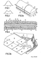
- an impedance matching structure which couples wideband pulses from the transducer to the human tissue should have a Gaussian frequency response as illustrated in Fig. 1.
- a transducer array is backed with air or a lossy material, a single quarterwave matching window will produce a double peaked frequency response of the type illustrated in Fig. 2.
- the prior art has recognized that a frequency response characteristic which approaches the ideal Gaussian may be achieved with an impedance matching structure comprising two or more quarterwave matching layers in cascade (that is one overlaying the other).
- the production of cascade matching structures of this type requires precise control of the matching layer thickness.
- a plurality of matching strips of different thicknesses are disposed, side by side, on the face of each element in a transducer array.
- each of the strips has a thickness of one quarter wavelength at some component frequency of the transmitted ultrasound energy.
- a single peaked frequency response, which approaches the ideal Gaussion, is thus achieved.
- the structure is relatively insensitive to minor variations in the thickness of the individual matching strips and may thus be manufactured by inexpensive sawing or pressing techniques.
- An impedance matching structure for coupling wideband sonic energy between one or more acoustic transducers and an object in accordance with the invention comprises a periodic array of stepped matching structures disposed side-by-side over an active surface of the transducers, each of the matching structures comprising two or more flat, parallel strips of sound-conductive material disposed, side-by-side, over the active surface in a stepped configuration wherein the thickness of successive strips increases monotonically across the structure.
- the matching strips comprise a periodic array of staircase-like structures disposed across the active face of a transducer array.
- the faces of the steps are disposed perpendicular to the scanning axis of the array.
- the width and height of strips in the structure vary from one step to the next.
- Figs. 3a and 3b illustrate a preferred embodiment of the invention which comprises a linear array of transducer elements.
- the elements are formed from a single rectangular block of piezoelectric ceramic material 10' which may, for example, comprise a type PZT-5 ceramic.
- the ceramic block 10 has a thickness resonance of approximately 3.5 MHz.
- the scanning axis of the array is indicated by arrow S.
- the active front surface of the ceramic block 10 is provided with an electrode 14.
- the back surface of the ceramic block 10 is coated with a copper electrode 16.
- the individual transducer elements 8 are then separated by sawing a series of parallel slots 18, perpendicular to the scanning axis, on the back surface across the width of the ceramic and copper electrode.
- a typical transducer array is produced from a cermaic block having a width of 16.9 mm and a length of 97.5 mm, 72 individual transducer elements, each 1.28 mm long, are produced by sawing the bar, through approximately 10% of its thickness, with a series of kerfs using a .06 mm diamond saw.
- each matching structure comprises a staircase-like structure of three parallel strips having front surfaces 21, 23 and 25 disposed at varying distances from the surface of the electrode 14.
- the thickness of the strips is chosen to be approximately one quarter wavelength at frequencies within the spectrum of the wideband pulses of ultrasound energy. At least one strip of each thickness should overlay each of the elements 8. It is not necessary, however, that the vertical faces of the steps 22, 24 be aligned with or correspond to the boundaries of the underlying transducer elements 8.
- the vertical faces of the steps 22, 24 extend parallel to the saw kerfs 18.
- the matching structure may be constructed with the vertical faces perpendicular to the saw kerfs or at an intermediate angle thereto. There is, likewise, no requirement that the width or thickness of the individual strips within each structure be uniform.
- the acoustic impedance of the matching strips should be the geometric mean of the acoustic impedances of the transducer and the test object.
- the impedance of the matching strips should lie between the impedance of the transducer and that of the test object.
- the matching structure is formed by casting a flat layer of epoxy resin loaded with tungsten powder on the front surface of the electrodes 14. A series of parallel grooves are then cut in the surface of the resin, using a programmed diamond saw, to produce the periodic staircase structures.
- surface 21 is .228 mm long and is disposed approximately .102 mm above the front surface of electrode 14; surface 23 is .127 mm long and is disposed .063 mm above the front surface of electrode 14; and surface 25 is .152 mm long and is disposed approximately .025 mm above the front surface of electrode 14.
- the tolerance of the surface flatness of the ceramic block 10 and the electrode 14 may be such that the saw cuts used to produce the lowest surface 25 actually expose the underlying electrode 14.
- the characteristics of the matching structure are such that its frequency response and other operating characteristics are not significantly deteriorated by the occasional absence of the thinnest portion of the matching layer 20 in structures along the array.
- the transducers are backed with a lossy air cell 40 (which may for example comprise epoxy resin loaded with glass micro-balloons) which is bonded to the surface of rear electrode 16 and fills the saw kerfs 18. Focussing across the width of the array may be achieved by casting a cylindrical acoustic lens 30 directly over the front of the matching structure. Typically the lens may comprise silicone rubber.
- Extensions of the back electrodes 16 on the surface of each transducer may be brought out of the sides of the array as tabs 60.
- an extension of the front electrode 14 may be brought out of the side of the array as tabs 50.
- the two end transducer elements of the array are inactive; tabs from the front electrode 50 are folded down to contact the back electrodes on these end elements to provide a ground plane connection.
- the matching device has been described herein with respect to preferred embodiments for use with a flat transducer array. Those skilled in the art will recognize, however, that the device is equally useful with curved transducer arrays and with single element transducers.
Landscapes
- Physics & Mathematics (AREA)
- Engineering & Computer Science (AREA)
- Acoustics & Sound (AREA)
- Multimedia (AREA)
- Transducers For Ultrasonic Waves (AREA)
- Ultra Sonic Daignosis Equipment (AREA)
Applications Claiming Priority (2)
| Application Number | Priority Date | Filing Date | Title |
|---|---|---|---|
| US137675 | 1980-04-07 | ||
| US06/137,675 US4326418A (en) | 1980-04-07 | 1980-04-07 | Acoustic impedance matching device |
Publications (1)
| Publication Number | Publication Date |
|---|---|
| EP0037620A1 true EP0037620A1 (fr) | 1981-10-14 |
Family
ID=22478561
Family Applications (1)
| Application Number | Title | Priority Date | Filing Date |
|---|---|---|---|
| EP81200393A Withdrawn EP0037620A1 (fr) | 1980-04-07 | 1981-04-06 | Dispositif d'adaptation d'impédance acoustique |
Country Status (4)
| Country | Link |
|---|---|
| US (1) | US4326418A (fr) |
| EP (1) | EP0037620A1 (fr) |
| JP (1) | JPS597280B2 (fr) |
| ES (1) | ES501036A0 (fr) |
Cited By (4)
| Publication number | Priority date | Publication date | Assignee | Title |
|---|---|---|---|---|
| EP0045989A3 (en) * | 1980-08-08 | 1982-12-01 | North American Philips Corporation | Acoustic impedance matching device |
| EP0308899A3 (fr) * | 1987-09-25 | 1990-03-14 | Siemens Aktiengesellschaft | Transducteur à ultrasons avec une caractéristique d'émission et réception astigmatique |
| US5229748A (en) * | 1989-04-12 | 1993-07-20 | Siemens Aktiengesellschaft | Monitoring system for monitoring the window panes of an interior, for example a motor vehicle interior |
| CN1103674C (zh) * | 1998-06-16 | 2003-03-26 | 国家淀粉及化学投资控股公司 | 能生物降解的膨化淀粉制品和其制备方法 |
Families Citing this family (31)
| Publication number | Priority date | Publication date | Assignee | Title |
|---|---|---|---|---|
| JPS59119698U (ja) * | 1983-01-31 | 1984-08-13 | 株式会社島津製作所 | 超音波探触子 |
| JPS60208196A (ja) * | 1984-04-02 | 1985-10-19 | Matsushita Electric Ind Co Ltd | 超音波探触子 |
| US4791072A (en) * | 1984-06-15 | 1988-12-13 | American Telephone And Telegraph Company, At&T Bell Laboratories | Method for making a complementary device containing MODFET |
| JPH0716280B2 (ja) * | 1985-02-08 | 1995-02-22 | 松下電器産業株式会社 | 超音波探触子 |
| JPS61184099A (ja) * | 1985-02-08 | 1986-08-16 | Matsushita Electric Ind Co Ltd | 超音波探触子 |
| DE3678635D1 (de) * | 1985-05-20 | 1991-05-16 | Matsushita Electric Industrial Co Ltd | Ultraschallwandler. |
| US4670683A (en) * | 1985-08-20 | 1987-06-02 | North American Philips Corporation | Electronically adjustable mechanical lens for ultrasonic linear array and phased array imaging |
| JPH02252979A (ja) * | 1989-03-27 | 1990-10-11 | Daikin Ind Ltd | アキシャルピストン機械 |
| US5275167A (en) * | 1992-08-13 | 1994-01-04 | Advanced Technology Laboratories, Inc. | Acoustic transducer with tab connector |
| US5423220A (en) * | 1993-01-29 | 1995-06-13 | Parallel Design | Ultrasonic transducer array and manufacturing method thereof |
| US20080027328A1 (en) * | 1997-12-29 | 2008-01-31 | Julia Therapeutics, Llc | Multi-focal treatment of skin with acoustic energy |
| US20060184071A1 (en) * | 1997-12-29 | 2006-08-17 | Julia Therapeutics, Llc | Treatment of skin with acoustic energy |
| CN1176157C (zh) * | 2002-12-26 | 2004-11-17 | 上海交通大学 | 用于隔声降噪的软质超高比重复合材料 |
| JP2006521902A (ja) * | 2003-03-31 | 2006-09-28 | ライポソニックス, インコーポレイテッド | 渦型トランスデューサー |
| US7857773B2 (en) * | 2003-12-30 | 2010-12-28 | Medicis Technologies Corporation | Apparatus and methods for the destruction of adipose tissue |
| US20050193451A1 (en) * | 2003-12-30 | 2005-09-01 | Liposonix, Inc. | Articulating arm for medical procedures |
| US20050154308A1 (en) * | 2003-12-30 | 2005-07-14 | Liposonix, Inc. | Disposable transducer seal |
| US8337407B2 (en) * | 2003-12-30 | 2012-12-25 | Liposonix, Inc. | Articulating arm for medical procedures |
| JP2007516810A (ja) * | 2003-12-30 | 2007-06-28 | ライポソニックス, インコーポレイテッド | 動作制御を有する超音波治療ヘッド |
| US7993289B2 (en) * | 2003-12-30 | 2011-08-09 | Medicis Technologies Corporation | Systems and methods for the destruction of adipose tissue |
| US20050154309A1 (en) * | 2003-12-30 | 2005-07-14 | Liposonix, Inc. | Medical device inline degasser |
| US20060122509A1 (en) * | 2004-11-24 | 2006-06-08 | Liposonix, Inc. | System and methods for destroying adipose tissue |
| US20080146970A1 (en) * | 2005-12-06 | 2008-06-19 | Julia Therapeutics, Llc | Gel dispensers for treatment of skin with acoustic energy |
| US8142200B2 (en) * | 2007-03-26 | 2012-03-27 | Liposonix, Inc. | Slip ring spacer and method for its use |
| US20090240146A1 (en) * | 2007-10-26 | 2009-09-24 | Liposonix, Inc. | Mechanical arm |
| MX2010008314A (es) * | 2008-02-01 | 2010-10-20 | Medicis Technologies Corp | Cabezal terapeutico para usarse con un sistema de ultrasonido. |
| US9707413B2 (en) * | 2010-03-09 | 2017-07-18 | Profound Medical Inc. | Controllable rotating ultrasound therapy applicator |
| US11027154B2 (en) | 2010-03-09 | 2021-06-08 | Profound Medical Inc. | Ultrasonic therapy applicator and method of determining position of ultrasonic transducers |
| US9530955B2 (en) * | 2011-11-18 | 2016-12-27 | Acist Medical Systems, Inc. | Ultrasound transducer and processing methods thereof |
| JP6162815B2 (ja) * | 2012-11-16 | 2017-07-12 | アシスト・メディカル・システムズ,インコーポレイテッド | 超音波振動子およびその処理方法 |
| US11678865B2 (en) * | 2017-12-29 | 2023-06-20 | Fujifilm Sonosite, Inc. | High frequency ultrasound transducer |
Citations (3)
| Publication number | Priority date | Publication date | Assignee | Title |
|---|---|---|---|---|
| US2430013A (en) * | 1942-06-10 | 1947-11-04 | Rca Corp | Impedance matching means for mechanical waves |
| US2922483A (en) * | 1954-06-03 | 1960-01-26 | Harris Transducer Corp | Acoustic or mechanical impedance |
| US3973152A (en) * | 1975-04-03 | 1976-08-03 | The United States Of America As Represented By The United States Energy Research And Development Administration | Ultrasonic transducer with laminated coupling wedge |
Family Cites Families (5)
| Publication number | Priority date | Publication date | Assignee | Title |
|---|---|---|---|---|
| US3663842A (en) * | 1970-09-14 | 1972-05-16 | North American Rockwell | Elastomeric graded acoustic impedance coupling device |
| US3971962A (en) * | 1972-09-21 | 1976-07-27 | Stanford Research Institute | Linear transducer array for ultrasonic image conversion |
| JPS5353393A (en) * | 1976-10-25 | 1978-05-15 | Matsushita Electric Ind Co Ltd | Ultrasonic probe |
| US4153894A (en) * | 1977-08-09 | 1979-05-08 | The United States Of America As Represented By The Secretary Of The Department Of Health, Education And Welfare | Random phase diffuser for reflective imaging |
| US4211948A (en) * | 1978-11-08 | 1980-07-08 | General Electric Company | Front surface matched piezoelectric ultrasonic transducer array with wide field of view |
-
1980
- 1980-04-07 US US06/137,675 patent/US4326418A/en not_active Expired - Lifetime
-
1981
- 1981-04-03 ES ES501036A patent/ES501036A0/es active Granted
- 1981-04-06 EP EP81200393A patent/EP0037620A1/fr not_active Withdrawn
- 1981-04-06 JP JP56051622A patent/JPS597280B2/ja not_active Expired
Patent Citations (3)
| Publication number | Priority date | Publication date | Assignee | Title |
|---|---|---|---|---|
| US2430013A (en) * | 1942-06-10 | 1947-11-04 | Rca Corp | Impedance matching means for mechanical waves |
| US2922483A (en) * | 1954-06-03 | 1960-01-26 | Harris Transducer Corp | Acoustic or mechanical impedance |
| US3973152A (en) * | 1975-04-03 | 1976-08-03 | The United States Of America As Represented By The United States Energy Research And Development Administration | Ultrasonic transducer with laminated coupling wedge |
Cited By (4)
| Publication number | Priority date | Publication date | Assignee | Title |
|---|---|---|---|---|
| EP0045989A3 (en) * | 1980-08-08 | 1982-12-01 | North American Philips Corporation | Acoustic impedance matching device |
| EP0308899A3 (fr) * | 1987-09-25 | 1990-03-14 | Siemens Aktiengesellschaft | Transducteur à ultrasons avec une caractéristique d'émission et réception astigmatique |
| US5229748A (en) * | 1989-04-12 | 1993-07-20 | Siemens Aktiengesellschaft | Monitoring system for monitoring the window panes of an interior, for example a motor vehicle interior |
| CN1103674C (zh) * | 1998-06-16 | 2003-03-26 | 国家淀粉及化学投资控股公司 | 能生物降解的膨化淀粉制品和其制备方法 |
Also Published As
| Publication number | Publication date |
|---|---|
| JPS597280B2 (ja) | 1984-02-17 |
| JPS56160196A (en) | 1981-12-09 |
| ES8205551A1 (es) | 1982-06-16 |
| US4326418A (en) | 1982-04-27 |
| ES501036A0 (es) | 1982-06-16 |
Similar Documents
| Publication | Publication Date | Title |
|---|---|---|
| US4326418A (en) | Acoustic impedance matching device | |
| US4385255A (en) | Linear array ultrasonic transducer | |
| US5945770A (en) | Multilayer ultrasound transducer and the method of manufacture thereof | |
| US4686408A (en) | Curvilinear array of ultrasonic transducers | |
| US6822374B1 (en) | Multilayer piezoelectric structure with uniform electric field | |
| JP2758199B2 (ja) | 超音波探触子 | |
| JP2651498B2 (ja) | 両面フエーズドアレイトランスデユーサ | |
| US5392259A (en) | Micro-grooves for the design of wideband clinical ultrasonic transducers | |
| US5640370A (en) | Two-dimensional acoustic array and method for the manufacture thereof | |
| US6225728B1 (en) | Composite piezoelectric transducer arrays with improved acoustical and electrical impedance | |
| US5423220A (en) | Ultrasonic transducer array and manufacturing method thereof | |
| EP0872285A2 (fr) | Transducteur composit avec élément arrière conductive | |
| EP0707898A2 (fr) | Procédé pour former intégralement un transducteur et des couches d'adaptation d'impédance | |
| EP0629993A2 (fr) | Couche d'adaptation pour adapter l'impédance acoustique des transducteurs cliniques ultrasonores | |
| US20030085635A1 (en) | Multidimensional ultrasonic transducer arrays | |
| US5371717A (en) | Microgrooves for apodization and focussing of wideband clinical ultrasonic transducers | |
| JPS6054600A (ja) | 複合電気トランスジユーサの製造方法 | |
| GB2098828A (en) | Ultrasonic transducer for single frequency applications | |
| WO1996011753A1 (fr) | Matrice de transducteurs a ultrasons soumis a une apodisation de la focalisation en elevation | |
| EP0045989B1 (fr) | Dispositif d'adaptation de l'impédance acoustique | |
| US4401910A (en) | Multi-focus spiral ultrasonic transducer | |
| Powell et al. | Flexible ultrasonic transducer arrays for nondestructive evaluation applications. II. Performance assessment of different array configurations | |
| DE3149732A1 (de) | Ultraschallwandleranordnung | |
| JPH07312799A (ja) | 超音波探触子とその製造方法 | |
| JPS6341022B2 (fr) |
Legal Events
| Date | Code | Title | Description |
|---|---|---|---|
| PUAI | Public reference made under article 153(3) epc to a published international application that has entered the european phase |
Free format text: ORIGINAL CODE: 0009012 |
|
| AK | Designated contracting states |
Designated state(s): DE FR GB IT SE |
|
| STAA | Information on the status of an ep patent application or granted ep patent |
Free format text: STATUS: THE APPLICATION IS DEEMED TO BE WITHDRAWN |
|
| 18D | Application deemed to be withdrawn |
Effective date: 19820919 |
|
| RIN1 | Information on inventor provided before grant (corrected) |
Inventor name: PELL, JAMES WILLIAM |