EP0037633B1 - Rotorblatt für Hubschrauber - Google Patents
Rotorblatt für Hubschrauber Download PDFInfo
- Publication number
- EP0037633B1 EP0037633B1 EP81300832A EP81300832A EP0037633B1 EP 0037633 B1 EP0037633 B1 EP 0037633B1 EP 81300832 A EP81300832 A EP 81300832A EP 81300832 A EP81300832 A EP 81300832A EP 0037633 B1 EP0037633 B1 EP 0037633B1
- Authority
- EP
- European Patent Office
- Prior art keywords
- rotor
- blade
- region
- outboard
- pitching moment
- Prior art date
- Legal status (The legal status is an assumption and is not a legal conclusion. Google has not performed a legal analysis and makes no representation as to the accuracy of the status listed.)
- Expired
Links
- 238000009826 distribution Methods 0.000 claims description 15
- 230000011514 reflex Effects 0.000 claims description 7
- 238000011068 loading method Methods 0.000 description 20
- 230000033001 locomotion Effects 0.000 description 20
- 230000000694 effects Effects 0.000 description 12
- 230000006872 improvement Effects 0.000 description 9
- 238000000034 method Methods 0.000 description 9
- 230000002829 reductive effect Effects 0.000 description 7
- 230000008901 benefit Effects 0.000 description 5
- UJCHIZDEQZMODR-BYPYZUCNSA-N (2r)-2-acetamido-3-sulfanylpropanamide Chemical compound CC(=O)N[C@@H](CS)C(N)=O UJCHIZDEQZMODR-BYPYZUCNSA-N 0.000 description 4
- 241001669680 Dormitator maculatus Species 0.000 description 4
- 230000008569 process Effects 0.000 description 4
- 238000013459 approach Methods 0.000 description 3
- 230000002441 reversible effect Effects 0.000 description 3
- 238000000926 separation method Methods 0.000 description 3
- 230000003068 static effect Effects 0.000 description 3
- 230000002411 adverse Effects 0.000 description 2
- 238000004458 analytical method Methods 0.000 description 2
- 230000000670 limiting effect Effects 0.000 description 2
- 238000004519 manufacturing process Methods 0.000 description 2
- 230000035939 shock Effects 0.000 description 2
- 230000015572 biosynthetic process Effects 0.000 description 1
- 230000008859 change Effects 0.000 description 1
- 238000010276 construction Methods 0.000 description 1
- 230000001419 dependent effect Effects 0.000 description 1
- 238000012938 design process Methods 0.000 description 1
- 230000001627 detrimental effect Effects 0.000 description 1
- 238000010586 diagram Methods 0.000 description 1
- 230000014509 gene expression Effects 0.000 description 1
- 206010020745 hyperreflexia Diseases 0.000 description 1
- 239000000203 mixture Substances 0.000 description 1
- 230000002028 premature Effects 0.000 description 1
- 230000009467 reduction Effects 0.000 description 1
- 238000010992 reflux Methods 0.000 description 1
- 230000008719 thickening Effects 0.000 description 1
Images




Classifications
-
- B—PERFORMING OPERATIONS; TRANSPORTING
- B64—AIRCRAFT; AVIATION; COSMONAUTICS
- B64C—AEROPLANES; HELICOPTERS
- B64C27/00—Rotorcraft; Rotors peculiar thereto
- B64C27/32—Rotors
- B64C27/46—Blades
- B64C27/463—Blade tips
Definitions
- This invention relates to helicopter rotor blades.
- a significant proportion of the empty weight of a helicopter is made up of the main rotor system, including the rotor blades and the hub, and the weight of this system is directly related to the blade area required to achieve a given speed-weight-altitude performance capability.
- the higher the blade loading level utilised the lighter will be the blades and hub, and the greater will be the aircraft's disposable load.
- the maximum blade loading level that may be used is determined by the aerodynamic processes which limit the rotor operating envelope in forward flight. These processes generally involve drag rise or flow separations over some portion of the rotor blades. On the advancing blades where the forward speed of the helicopter is added to the rotational velocity of the rotor blade, high Mach numbers can be attained with resulting drag rise and, ultimately, shock induced separations. Experience has shown that advancing blade limiting conditions may be penetrated by considerable margins, but other rotor limitations are more severe.
- the objective of the present invention is the general improvement of helicopter rotor performance by facilitating the design and successful operation of practical rotor systems having desirably high blade loading.
- the invention seeks to enable improvements of the rotor stall flutter envelope because of its importance to rotor performance generally: and specifically to enable the theoretical advantages of aft-loaded, high lift, aerofoil sections to be realised in a practical rotor configuration.
- US-A-3,721,507 discloses a rotor blade having a swept and thinned tip portion designed to alleviate instability and mentions the use of an aerofoil section, for this tip portion, that is known to have a small negative basic pitching moment coefficient (about -0.007); in the inboard region of the blade there is used a section known to have zero basic pitching moment: US-A-3,721,507 can thus be said to disclose-but in the context of a special tip formation for purposes different from the objective of this invention-a helicopter rotor blade having a root end for attachment to a rotor head, a tip end defining the end of the blade farthest from the root end, and a central portion of aerofoil section extending between and attached to the root end and the tip end, an outboard region of this central portion having a negative basic pitching moment coefficient.
- a helicopter rotor blade having a root end for attachment to a rotor head, a tip end defining the end of the blade farthest from the root end, and a central portion of aerofoil section extending between and attached to the root end and the tip end, an outboard region of the central portion having a negative basic pitching moment coefficient, is characterised, in one aspect of the invention, in that said outboard region has a negative basic pitching moment coefficient of absolute value not less than 0.02, whereas an inboard region of said central portion has a basic pitching moment coefficient more positive than that of said outboard region.
- the outboard region may comprise a region outboard of the seventy per cent rotor radius station and may extend between said seventy per cent station and the eighty per cent radius station.
- the inboard and outboard regions and the outboard and tip regions are blended smoothly together.
- the respective pitching moment characteristics of the inboard and outboard regions of the central portion may be obtained by camber distribution in the respective aerofoil sections, and the camber of the aerofoil section of the inboard region may comprise a reflex camber.
- the tip end may be swept rearwardly with respect to the central portion and may have a thickness to chord ratio less than that of the central portion.
- a helicopter rotor blade having a root end for attachment to a rotor head, a tip end defining the end of the blade farthest from the root end and a central portion of aerofoil section extending between and attached to the root end and the tip end and co-operating therewith to define a rotor radius, an outboard region of said central portion having a negative basic pitching moment coefficient, is characterised, in another aspect of the invention, in that said outboard region has a negative basic pitching moment coefficient of absolute value not less than 0.02 and in that an inboard region of said central portion has a positive basic pitching moment coefficient.
- said negative and positive basic pitching moment coefficients each have an absolute value greater than 0.02.
- the basic pitching moment coefficient of the outboard region may be between minus 0.02 and minus 0.04 and the basic pitching moment coefficient of the inboard region may be between 0.02 and 0.04.
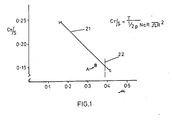
- a typical rotor envelope is shown in Figure 1, expressed in terms of a non-dimensional blade loading coefficient, C TlS and a non-dimensional forward speed or advance ratio, p.
- the retreating blade stall flutter limit indicated at 21 is shown as a function of advance ratio alone.
- the advancing blade high Mach number 'soft' limit 22 may be placed on the same diagram as shown.
- Figure 1 shows that the higher the advance ratio required of the rotor, the lower is the maximum allowable blade loading. For an aircraft of a given weight, the higher the design speed, the greater will be the required blade area, and the higher will be the aircraft's empty weight fraction. A typical rotor blade design point is indicated at A on Figure 1.
- improved aerofoil section performance may be used to reduce rotor blade areas and rotor system weight, or, for the same blade area, to increase aircraft gross weight, speed or altitude capability.
- improved aerofoil section performance may be used to reduce rotor blade tip speeds.
- RAE 9615 aerofoil section was derived directly from NACA 0012 by the addition of nose droop while leaving the aft part of the aerofoil section unaltered, thus producing a worthwhile increase in C LMAX for a small increase in basic pitching moment coefficient.
- More recent high performance sections indicated at B in Figure 2 make use of greater nose droop, and contain basic pitching moment growth by means of trailing edge reflex or reversed aft loading, as indicated by line 24 representative of increased aft loading and constant nose droop.
- the direction of increased reflex camber is indicated by arrow 25.
- the total pitching moment coefficient is made up of three parts:
- C Mo is negative or nose down, and the once per rev component of the blade twisting moment acts to decrease pitch on the advancing blade, causing a conventional rotor to flap forward and increase its forward speed. Since the original twisting moment is proportional to forward speed, a speed instability is possible. This component also leads to a flattening of the usual control gradients and can lead to control reversals especially in rotor blades employing an aft-loaded aerofoil section uniformly throughout their span.
- helicopter rotor blades do not require a high level of aerodynamic performance uniformly throughout their spans, and this invention utilises this feature to provide a technique by which the benefits of aft-loaded aerofoil sections may be extended to helicopter main rotor blades or the rotor blades of autogyros which previously were too soft in torsion to make use of such sections.
- the extent of the less critical inboard region depends on the design speed of the rotor. Generally as the design speed rises, the inboard region expands and a rotor blade according to this invention employs a reflex camber distribution or sections of reduced camber in this inboard region to counteract the undesirable effects of a high camber aerofoil section utilised in an outboard region in order to improve overall blade performance. As the rotor design speed rises, and the highest section performance requirements become more concentrated radially, this technique becomes increasingly powerful.
- a rotor blade constructed in accordance with this invention exploits the performance advantages of aft-loaded aerofoil sections, or indeed any section which derives improved stalling performance at the expense of elevated basic pitching moment, based on the fact that inboard aerofoil sections do not require as high a performance (C LMAX ) as do outboard sections, and need not satisfy the same performance constraints.
- the invention utilises aerofoil sections with a high degree of reflex or reverse aft-loading in an inboard region of the blade span in combination with a high performance outboard region in order to reduce or zero the net blade aerodynamic moment. It has been found that the reduction in C LMAX of inboard sections associated with reflex (see Figure 2) can be tolerated in such a configuration.
- the first step in defining the geometry of a rotor blade according to this invention is to consider the region in which the highest performance will be required, i.e., the region in which the product of local incidence (C L ) times local dynamic head is highest on the retreating side of the rotor disc.
- This region will generally be outboard of seventy per cent rotor radius for rotors designed for high speed operation and will end somewhat inboard of the tip.
- the highly cambered section of the outboard region need not be extended to the extreme blade tip since tip effects tend to reduce incidence requirements in this area. It may, therefore, be advantageous to washout camber, in particular leading edge droop, and aerofoil thickness at the tip end of a rotor blade to obtain drag advantages on the advancing blade.
- the highly cambered section of highest retreating blade performance may extend to the tip to ease manufacture.
- a helicopter rotor blade constructed in accordance with one embodiment of the invention includes a root end 14 for attachment to a helicopter rotor head (not shown), and a tip end 15. It will be noted in the illustrated embodiment that the root end 14 is located at a thirty per cent (0.3 R) rotor radius station, i.e., thirty per cent of the rotor radius (1.0 R) from the axis of rotation of the rotor blade.
- a central portion 16 having a constant thickness to chord ratio of twelve per cent extends between the root end 14 and the tip 15 and together the root end 14, the portion 16 and tip 15 define an operating rotor blade radius (1.0 R).
- an inboard region 17 of the rotor blade extending to the seventy per cent rotor radius station (0.7 R) comprises a reflexed camber aerofoil section, C
- an outboard region 18 between the seventy per cent and eighty per cent rotor radius (0.8 R) stations comprises an aft-loaded aerofoil section D.
- the tip of the blade comprises a rearwardly swept portion 19 of progressively thinned aerofoil section, and is constructed as disclosed in GB-A-1,538,055..
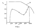
- section D in the outboard region exhibits a high static maximum lift coefficient between 1.5 and 1.6 and a negative basic pitching moment coefficient between minus 0.02 and minus 0.04, whereas section C in the inboard region has a reduced static maximum lift coefficient between 1.4 and 1.5 and a positive basic pitching moment coefficient between plus 0.02 and 0.04.
- Corresponding values for existing rotor blade sections NACA 0012 and RAE 9615 are illustrated on Figure 7.
- the helicopter rotor blade of this invention makes use of a highly cambered aerofoil section or sections providing a basic pitching moment coefficient more negative than minus 0.02 either through aft loading or extreme nose droop in an outboard region whose extent is influenced by aerodynamic performance considerations, and inboard of which the blade camber is either reduced or reflexed to provide a basic pitching moment coefficient more positive than minus 0.02 to offset the undesirable effects of the outboard region camber.
- the outboard region 18 has a basic nose down pitching moment greater than that of the inboard region 17 and it is noted that this includes an arrangement in which the inboard region has either a basic pitching moment coefficient less negative than that of the outboard region, or a positive (nose-up) basic pitching moment coefficient. These two regions may be blended smoothly together.
- the outboard region of high camber need not extend to the extreme blade tip. In fact, such a region may be employed inboard of a tip of a modified geometry employing sweep, taper, platform area change and so forth as shown in Figure 6, provided its undesirable pitching moment effects are counteracted by the camber distribution of the inboard region of the blade.
- the degree and distribution of camber in the inboard region depends on the radial extent of the outboard region and the amount of camber employed there, upon the stiffness of the blade in torsion and the amount of torsional motion which can be tolerated and upon the blade planform geometry.
- the radial station e is established from rotor performance considerations.
- a blend region or a continuous variation camber may be employed between the inboard and outboard regions:
- each harmonic is quite similar in form.
- a value of the ratio CMo 2 /CMo 1 can be chosen to zero any particular harmonic; for soft blade, the motion and control load of a particular harmonic cannot be made zero at the same time. If a particular motion or control load harmonic is set to zero, there will be left over motions or control loads in other harmonics.
- the ratio for the steady harmonic component is also a function of advance ratio.
- the important once/rev component of torsional motion may therefore be set to zero for all forward speeds through suitable choice of the ratio CMo 2 /CMo 1 for a given value of e.
- the steady component will also be reduced significantly at all forward speeds and the second harmonic motion will be reduced to a constant fraction of what it would have been if the high performance outboard section had been used uniformly down the span of the blade.
- CMo 2 /CMo 1 -1.915 or the nose up-basic moment of the inboard section must be nearly twice the nose down basic moment of the outboard section.
- the present invention provides a rotor blade in which the advantages of aerofoil sections of high basic pitching moment may be extended to helicopters or autogyro main rotors, or rotors with blades relatively supple in torsion.
- the construction employed minimises the effects of high basic pitching moments, high blade root torsional moments and control loads, and undesirable blade torsional motion, thus allowing the rotor blade to behave in a conventional manner while attaining high levels of blade loading. This is achieved by offsetting the high moments produced by high performance sections used in outboard regions of the blade with sections of reduced or reflexed camber used inboard in regions less critical from a performance point of view.
Landscapes
- Engineering & Computer Science (AREA)
- Mechanical Engineering (AREA)
- Aviation & Aerospace Engineering (AREA)
- Structures Of Non-Positive Displacement Pumps (AREA)
- Wind Motors (AREA)
Claims (12)
Applications Claiming Priority (2)
| Application Number | Priority Date | Filing Date | Title |
|---|---|---|---|
| GB8010639 | 1980-03-28 | ||
| GB8010639 | 1980-03-28 |
Publications (2)
| Publication Number | Publication Date |
|---|---|
| EP0037633A1 EP0037633A1 (de) | 1981-10-14 |
| EP0037633B1 true EP0037633B1 (de) | 1986-07-30 |
Family
ID=10512489
Family Applications (1)
| Application Number | Title | Priority Date | Filing Date |
|---|---|---|---|
| EP81300832A Expired EP0037633B1 (de) | 1980-03-28 | 1981-02-27 | Rotorblatt für Hubschrauber |
Country Status (4)
| Country | Link |
|---|---|
| US (1) | US4427344A (de) |
| EP (1) | EP0037633B1 (de) |
| JP (1) | JPS56149297A (de) |
| DE (1) | DE3175016D1 (de) |
Families Citing this family (16)
| Publication number | Priority date | Publication date | Assignee | Title |
|---|---|---|---|---|
| FR2490586A1 (fr) * | 1980-09-24 | 1982-03-26 | Aerospatiale | Profil de pale pour voilure tournante d'aeronef |
| CA1243993A (en) * | 1983-07-04 | 1988-11-01 | Westland Plc | Helicopter rotor blade |
| GB9112835D0 (en) * | 1991-06-14 | 1992-05-27 | Westland Helicopters | Helicopter rotor blades |
| US5597138A (en) * | 1991-09-30 | 1997-01-28 | Arlton; Paul E. | Yaw control and stabilization system for helicopters |
| GB2312712A (en) * | 1996-04-30 | 1997-11-05 | Gkn Westland Helicopters Ltd | Propeller/rotor blade |
| US5749540A (en) * | 1996-07-26 | 1998-05-12 | Arlton; Paul E. | System for controlling and automatically stabilizing the rotational motion of a rotary wing aircraft |
| JP3170470B2 (ja) * | 1997-03-24 | 2001-05-28 | 株式会社コミュータヘリコプタ先進技術研究所 | 回転翼機のロータブレード |
| JP3916723B2 (ja) * | 1997-05-15 | 2007-05-23 | 富士重工業株式会社 | 回転翼航空機の回転翼羽根 |
| DE19743694C2 (de) | 1997-10-02 | 2001-11-15 | Aloys Wobben | Rotorblatt und Windenergieanlage mit einem Rotorblatt |
| AU3303299A (en) * | 1998-02-20 | 1999-09-06 | Abraham E. Karem | Optimum speed rotor |
| US6641365B2 (en) | 1998-02-20 | 2003-11-04 | Abraham E. Karem | Optimum speed tilt rotor |
| US7252479B2 (en) * | 2005-05-31 | 2007-08-07 | Sikorsky Aircraft Corporation | Rotor blade for a high speed rotary-wing aircraft |
| US7547193B2 (en) | 2005-07-22 | 2009-06-16 | Sikorsky Aircraft Corporation | Rotor blade assembly with high pitching moment airfoil section for a rotary wing aircraft |
| US7854593B2 (en) * | 2006-02-16 | 2010-12-21 | Sikorsky Aircraft Corporation | Airfoil for a helicopter rotor blade |
| KR101009497B1 (ko) * | 2008-12-12 | 2011-01-19 | 한국항공우주연구원 | 헬리콥터 로터 블레이드 안쪽부위 에어포일 |
| CN112977814B (zh) * | 2021-03-04 | 2022-03-08 | 南京航空航天大学 | 适用于中小型无人倾转旋翼飞行器的改进型旋翼气动外形 |
Family Cites Families (7)
| Publication number | Priority date | Publication date | Assignee | Title |
|---|---|---|---|---|
| US3721507A (en) * | 1971-09-22 | 1973-03-20 | United Aircraft Corp | Blade for high speed helicopter |
| US3728045A (en) * | 1971-09-22 | 1973-04-17 | United Aircraft Corp | Helicopter blade |
| US3822105A (en) * | 1971-09-22 | 1974-07-02 | United Aircraft Corp | Helicopter blade |
| GB1450965A (en) * | 1973-12-28 | 1976-09-29 | Boeing Co | Rotor blades for rotorcraft |
| GB1538055A (en) * | 1975-05-19 | 1979-01-10 | Westland Aircraft Ltd | Helicopter rotor blades |
| US4142837A (en) * | 1977-11-11 | 1979-03-06 | United Technologies Corporation | Helicopter blade |
| US4248572A (en) | 1978-12-11 | 1981-02-03 | United Technologies Corporation | Helicopter blade |
-
1981
- 1981-02-27 EP EP81300832A patent/EP0037633B1/de not_active Expired
- 1981-02-27 DE DE8181300832T patent/DE3175016D1/de not_active Expired
- 1981-03-13 US US06/243,498 patent/US4427344A/en not_active Expired - Lifetime
- 1981-03-26 JP JP4328181A patent/JPS56149297A/ja active Pending
Also Published As
| Publication number | Publication date |
|---|---|
| US4427344A (en) | 1984-01-24 |
| DE3175016D1 (en) | 1986-09-04 |
| JPS56149297A (en) | 1981-11-19 |
| EP0037633A1 (de) | 1981-10-14 |
Similar Documents
| Publication | Publication Date | Title |
|---|---|---|
| EP3178739B1 (de) | Rotorblatttorsionsverlauf für einen hochgeschwindigkeitsdrehflügler | |
| US4427344A (en) | Helicopter rotor blade | |
| US6000911A (en) | Blade with swept-back tip for the rotary wings of an aircraft | |
| US4668169A (en) | Helicopter rotor blade | |
| EP1984244B1 (de) | Blatt für eine hubschrauberrotorschaufel | |
| US3721507A (en) | Blade for high speed helicopter | |
| US8066219B2 (en) | Anhedral tip blades for tiltrotor aircraft | |
| EP1585665B1 (de) | Propellerblatt mit führungskantennut | |
| EP1893483B1 (de) | Rotorblatt für ein hochgeschwindigkeits-drehflügelflugzeug | |
| GB2067493A (en) | Helicopter rotor blade tip | |
| US5199851A (en) | Helicopter rotor blades | |
| US5584661A (en) | Forward sweep, low noise rotor blade | |
| JP2620087B2 (ja) | 回転翼航空機用ブレード | |
| EP0518598B1 (de) | Rotorblätter eines Hubschraubers | |
| US5927948A (en) | Propeller | |
| EP0113466A1 (de) | Flügel mit verjüngter relativer Profildicke | |
| US4028003A (en) | Torsionally compliant helicopter rotor blade with improved stability and performance characteristics | |
| US2135700A (en) | Autorotative wing for aircraft | |
| RU2145293C1 (ru) | Лопасть винта и аэродинамический профиль лопасти (варианты) | |
| JPS6317680B2 (de) | ||
| Benson et al. | Influence of airfoils on stall flutter boundaries of articulated helicopter rotors | |
| Hansford | Rotor load correlation with the British Experimental Rotor Program blade | |
| Chan et al. | Performance enhancement evaluation of an actuated trailing edge flap | |
| Walsh et al. | Rotor blade aerodynamic design | |
| GB2142597A (en) | Helicopter rotor blade |
Legal Events
| Date | Code | Title | Description |
|---|---|---|---|
| PUAI | Public reference made under article 153(3) epc to a published international application that has entered the european phase |
Free format text: ORIGINAL CODE: 0009012 |
|
| AK | Designated contracting states |
Designated state(s): DE FR GB IT |
|
| 17P | Request for examination filed |
Effective date: 19820305 |
|
| RAP1 | Party data changed (applicant data changed or rights of an application transferred) |
Owner name: WESTLAND PLC |
|
| ITF | It: translation for a ep patent filed | ||
| GRAA | (expected) grant |
Free format text: ORIGINAL CODE: 0009210 |
|
| AK | Designated contracting states |
Kind code of ref document: B1 Designated state(s): DE FR GB IT |
|
| REF | Corresponds to: |
Ref document number: 3175016 Country of ref document: DE Date of ref document: 19860904 |
|
| ET | Fr: translation filed | ||
| PLBE | No opposition filed within time limit |
Free format text: ORIGINAL CODE: 0009261 |
|
| STAA | Information on the status of an ep patent application or granted ep patent |
Free format text: STATUS: NO OPPOSITION FILED WITHIN TIME LIMIT |
|
| 26N | No opposition filed | ||
| ITTA | It: last paid annual fee | ||
| PGFP | Annual fee paid to national office [announced via postgrant information from national office to epo] |
Ref country code: DE Payment date: 19930308 Year of fee payment: 13 |
|
| PG25 | Lapsed in a contracting state [announced via postgrant information from national office to epo] |
Ref country code: DE Effective date: 19941101 |
|
| PGFP | Annual fee paid to national office [announced via postgrant information from national office to epo] |
Ref country code: FR Payment date: 20000210 Year of fee payment: 20 |
|
| PGFP | Annual fee paid to national office [announced via postgrant information from national office to epo] |
Ref country code: GB Payment date: 20000223 Year of fee payment: 20 |
|
| PG25 | Lapsed in a contracting state [announced via postgrant information from national office to epo] |
Ref country code: GB Free format text: LAPSE BECAUSE OF EXPIRATION OF PROTECTION Effective date: 20010226 |
|
| REG | Reference to a national code |
Ref country code: GB Ref legal event code: PE20 Effective date: 20010226 |