EP0037645A1 - Dispositif rotatif de peinture électrostatique - Google Patents
Dispositif rotatif de peinture électrostatique Download PDFInfo
- Publication number
- EP0037645A1 EP0037645A1 EP81301070A EP81301070A EP0037645A1 EP 0037645 A1 EP0037645 A1 EP 0037645A1 EP 81301070 A EP81301070 A EP 81301070A EP 81301070 A EP81301070 A EP 81301070A EP 0037645 A1 EP0037645 A1 EP 0037645A1
- Authority
- EP
- European Patent Office
- Prior art keywords
- wall
- rotary shaft
- painting device
- spray painting
- electrostatic spray
- Prior art date
- Legal status (The legal status is an assumption and is not a legal conclusion. Google has not performed a legal analysis and makes no representation as to the accuracy of the status listed.)
- Granted
Links
Images


Classifications
-
- B—PERFORMING OPERATIONS; TRANSPORTING
- B05—SPRAYING OR ATOMISING IN GENERAL; APPLYING FLUENT MATERIALS TO SURFACES, IN GENERAL
- B05B—SPRAYING APPARATUS; ATOMISING APPARATUS; NOZZLES
- B05B5/00—Electrostatic spraying apparatus; Spraying apparatus with means for charging the spray electrically; Apparatus for spraying liquids or other fluent materials by other electric means
- B05B5/025—Discharge apparatus, e.g. electrostatic spray guns
- B05B5/04—Discharge apparatus, e.g. electrostatic spray guns characterised by having rotary outlet or deflecting elements, i.e. spraying being also effected by centrifugal forces
- B05B5/0415—Driving means; Parts thereof, e.g. turbine, shaft, bearings
-
- B—PERFORMING OPERATIONS; TRANSPORTING
- B05—SPRAYING OR ATOMISING IN GENERAL; APPLYING FLUENT MATERIALS TO SURFACES, IN GENERAL
- B05B—SPRAYING APPARATUS; ATOMISING APPARATUS; NOZZLES
- B05B5/00—Electrostatic spraying apparatus; Spraying apparatus with means for charging the spray electrically; Apparatus for spraying liquids or other fluent materials by other electric means
- B05B5/025—Discharge apparatus, e.g. electrostatic spray guns
- B05B5/04—Discharge apparatus, e.g. electrostatic spray guns characterised by having rotary outlet or deflecting elements, i.e. spraying being also effected by centrifugal forces
- B05B5/0403—Discharge apparatus, e.g. electrostatic spray guns characterised by having rotary outlet or deflecting elements, i.e. spraying being also effected by centrifugal forces characterised by the rotating member
- B05B5/0407—Discharge apparatus, e.g. electrostatic spray guns characterised by having rotary outlet or deflecting elements, i.e. spraying being also effected by centrifugal forces characterised by the rotating member with a spraying edge, e.g. like a cup or a bell
Definitions
- the present invention relates to a rotary type electrostatic spray painting device.
- a rotary type electrostatic spray painting device which comprises a rotary shaft supported by ball bearings or roller bearings within the housing of the painting device, and a cup shaped spray head fixed onto the frond end of the rotary shaft.
- a negative high voltage is applied to the spray head, and paint is fed onto the inner circumferential wall of the spray head.
- fine paint particles charged with electrons are sprayed from the spray head and are attracted by the electrical force onto the surface of the body of a motor car, which is grounded. As a result of this, the surface of the body of a motor car is painted.
- the rotating speed of the spray head is about 20,000 r.p.m.
- the size of the particles of paint is relatively large and, thus, it is difficult to form a beautiful finished surface by using such a conventional rotary type electrostatic spray painting device.
- the painting process for bodies of motor cars comprises a primary spraying step, an undercoating step and a finish painting step.
- a conventional rotary type electrostatic spray painting device is used for carrying out the undercoating step, but cannot be used for carrying out the finish painting step.
- a jet lubricating system As a method of lubricating bearings, a jet lubricating system has been known, in which, by injecting the lubricating oil of a low viscosity into the region between the inner race and the outer race of the ball or roller bearing, the friction between the ball or roller and such races is greatly reduced and, at the same time, the heat caused by the friction is absorbed by the lubricating oil.
- the above-mentioned jet lubricating system is applied to a rotary type electrostatic spray painting device, it is possible to increase the rotating speed of the rotary shaft of the electrostatic spray painting device as compared with the case wherein grease lubricating bearings are used.
- the jet lubricating system requires a complicated lubricating oil feed device having a large size, it is particularly difficult to apply such a jet lubricating system to a rotary type electrostatic spray painting device.
- the lubricating oil is mixed with the paint, the appearance of the paint surface is damaged. Therefore, if the jet lubricating system is applied to a rotary type electrostatic spray painting device, it is necessary to completely prevent the lubricating oil from leaking into the paint.
- an air injection type electrostatic spray painting device in which the paint is divided into fine particles by the stream of injection air.
- this air injection type electrostatic spray painting device since the size of the particles of sprayed paint can be reduced to a great extent, as mentioned above, it is possible to form a beautiful finished surface. Consequently, in a field of manufacturing motor cars, the air injection type electrostatic spray painting device is adopted for carrying out the finish painting step for the bodies of motor cars.
- An object of the present invention is to provide a rotary type electrostatic spray painting device capable of reducing the size of the particles of paint to be sprayed and reducing the quantity of paint used.
- a rotary type electrostatic spray painting device comprising: a metallic housing; a metallic rotary shaft rotatably arranged in said housing and having a front end and a rear end; a cup shaped metallic spray head fixed onto the front end of said rotary shaft and having a cup shaped inner wall and an approximately cylindrical inner wall which is spaced radially inwardly from said cup shaped inner wall and defines an annular space therein, said approximately cylindrical inner wall being arranged coaxially with a rotation axis of said rotary shaft and having a plurality of paint outflow bores, each being formed in said approximately cylindrical inner wall and smoothly connected to said cup shaped inner wall; feed means having a paint injection nozzle which is arranged in said annular space and is directed to said approximately cylindrical inner wall for feeding a paint onto said approximately cylindrical inner wall; drive means cooperating with said rotary shaft for rotating said rotary shaft; non-contact type radial bearing means arranged in said housing and cooperating with said rotary shaft for radially supporting said rotary shaft
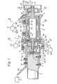
- a rotary type electrostatic spray painting device generally designated by reference numeral 1, comprises a generally hollow cylindrical front housing 2 made of metallic material, and a generally hollow cylindrical rear housing 3 made of metallic material.
- the front housing 2 and the rear housing 3 are firmly joined to each other by bolts 4.
- a support rod 6, made of electrically insulating material, is fitted into a cylindrical hole 5 formed in the rear housing 3, and this read housing 3 is fixed onto the support rod 6 by bolts 7.
- the support rod 6 is supported by a base (not shown).
- a rotary shaft 8 is inserted into the front housing 2.
- This rotary shaft 8 comprises a hollow cylindrical portion 8a located in the middle thereof, a shaft portion 8b formed in one piece on the front end of the hollow cylindrical portion 8a, and a shaft portion 8c fixed onto the rear end of the hollow cylindrical portion 8a.
- a spray head 9 made of metallic material is fixed onto the shaft portion 8b of the rotary shaft 8 by a nut 10.
- the spray head 9 comprises a spray head supporting member 12 forming therein an annular space 11, and a cup shaped spray head body 13 fixed onto the spray head supporting member 12.
- a plurality of paint outflow bores 16, each opening into the annular space 11 and smoothly connected to an inner wall 15 of the spray head body 13, is formed in an outer cylindrical portion 14 of the spray head supporting member 12.
- an end plate 17 is fixed onto the front .end of the front housing 2, and a paint injector 18 is mounted on the end plate 17.
- the paint injector 18 is connected to a paint reservoir 20 via a paint feed pump 19 and, as illustrated in Fig. 5, a nozzle 21 of the paint injector 18 is directed to the central portion of the cylindrical inner wall 14a of the outer cylindrical portion 14.
- a nozzle 21 of the paint injector 18 is directed to the central portion of the cylindrical inner wall 14a of the outer cylindrical portion 14.
- the direction of the nozzle 21 of the paint injector 18 is arranged to be inclined by an angle a towards the rotating direction of the spray head 9 with respect to the line t passing through the nozzle 21 and the rotation axis 0 of the rotary shaft 8.
- a pair of non-contact type tilting pad radial air bearings 22 and 23 is arranged in the front housing 2, and the rotary shaft 8 is rotatably supported on the front housing 2 via a pair of the tilting pad radial air bearings 22 and 23.
- Both the tilting pad radial air bearings 22 and 23 have the same construction and, therefore, the construction of only the tilting pad radial air bearing 22 will be hereinafter described.
- the tilting pad radial air bearing 22 comprises three pads 24, 25, 26 arranged to be spaced from the outer circumferential wall of the hollow cylindrical portion 8a of the rotary shaft 8 by an extremely small distance, and three support pins 27, 28, 29 supporting the pads 24, 25, 26, respectively.
- Spherical tips 30, 31, 32 are formed in one piece on the inner ends of the support pins 27, 28, 29 and are in engagement with spherical recesses formed on the rear faces of the pads 24, 25, 26, respectively. Consequently, the pads 24, 25, 26 can swing about the corresponding spherical tips 30, 31, 32, each functioning as a fulcrum.
- a bearing support frame 33 is fixed onto the outer circumferential wall of the front housing 2 by means of, for example, bolts (not shown), and the support pins 28, 29 are fixed onto the bearing support frame 33 by means of nuts 34, 35, respectively.
- a support arm 36 having a resilient plate shaped portion 36a is fixed onto the bearing support frame 33 by means of a bolt 37, and the other end of the support arm 36 is fixed onto the support pin 27 by means of a nut 38. Consequently, the pad 24 is urged onto the hollow cylindrical portion 8a of the rotary shaft 8 due to the resilient force of the support arm 36.
- a pair of disc shaped runners 39, 40 is inserted into the shaft portion 8c of the rotary shaft 8 and fixed onto the shaft portion 8c via a spacer 41 and a turbine wheel 42 by means of. a nut 43.
- a stationary annular plate 44 is arranged between the runners 39 and 40, and the runners 39, 40 and the annular plate 44 construct a non-contact type thrust air bearing.
- each of the runners 39, 40 is arranged to be spaced from the annular plate 44 by a slight distance.
- the annular plate 44 is fixed onto the front housing 2 via a pair of O rings 45, 46. As illustrated in Figs.
- annular groove 47 extending along the outer circumferential wall of the annular plate 44, is formed on the inner wall of the front housing 2 and connected to an air feed pump 49 via a compressed air supply hole 48 which is formed in the front housing 2.
- a plurality of air passages 50 each extending radially inwardly from the annular groove 47, is formed in the annular plate 44.
- a plurality of air outflow bores 51 each extending towards the runner 40 from the inner end portion of the corresponding air passage 50, is formed in the annular plate 44
- a plurality of air outflow bores 52 each extending towards the runner 39 from the inner end portion of the corresponding air passage 50, is formed in the annular plate 44.
- a turbine nozzle holder 53 is fixed onto the front housing 2 at a position adjacent to the annular plate 44, and an annular air supply chamber 54 is formed between the turbine nozzle holder 53 and the front housing 2.
- the air supply chamber 54 is connected to a compressor 56 via a compressed air supply hole 55.
- the air supply chamber 54 comprises a compressed air injecting nozzle 57 having a plurality of guide vanes (not shown), and turbine blades 58 of the turbine wheel 42 are arranged to face the compressed air injecting nozzle 57.
- a housing interior chamber 59, in which the turbine wheel 42 is arranged, is connected to the atmosphere via a discharge hole 60 which is formed in the rear housing 3.
- the compressed air fed into the air supply chamber 54 from the compressor 56 is injected into the housing interior chamber 59 via the compressed air injecting nozzle 57.
- the compressed air injected from the injecting nozzle 57 provides the rotational force for the turbine wheel 42 and, thus, the rotary shaft 8 is rotated at a high speed.
- the compressed air injected from the injecting nozzle 57 is discharged to the atmosphere via the discharge hole 60.
- a through-hole 62 is formed on an end wall 61 of the rear housing 3, which defines the housing interior chamber 59, and an electrode holder 63 extending through the through-hole 62 is fixed onto the end wall 61 by means of bolts 64.
- a cylindrical hole 65 is formed coaxially with the rotation axis of the rotary shaft 8 in the electrode holder 63, and a cylindrical electrode 66, made of wear resisting materials such as carbon, is inserted into the cylindrical hole 65 so as to be movable therein.
- a compression spring 67 is inserted between the electrode 66 and the electrode holder 63 so that the tip face 68 of the electrode 66 is urged onto the end face of the shaft portion 8c of the rotary shaft 8 due to the spring force of the compression spring 67.
- An external terminal 69 is fixed onto the outer wall of the rear housing 3 by means of bolts 70 and connected to a high voltage generator 71 used for generating a negative high voltage ranging from -60 KV to -90 KV. Consequently, the negative high voltage is applied to both the front housing 2 and the rear housing 3, and it is also applied to the spray head 9 via the electrode 66 and the rotary shaft 8.
- the rotary shaft 8 is supported by a pair of the tilting pad radial air bearings 22, 23, and a single thrust air bearing which is constructed by the runners 39, 40 and the stationary annular plate 44.
- the tilting pad radial air bearings 22, 23, when the rotary shaft 8 is rotated, ambient air is sucked into the extremely small clearances formed between the hollow cylindrical portion 8a and the pads 23, 25, 26. Then, the air thus sucked is compressed between the hollow cylindrical portion 8a and the pads 24, 25, 26 due to a so-called wedge effect of air, and therefore, the pressure of the air between the hollow cylindrical portion 8a and the pads 24, 25, 26 is increased.
- the rotary shaft 8 is supported by the thrust air bearing and a pair of the radial air bearings under a non-contacting state via a thin.air layer.
- the coefficient of viscosity of air is about one thousandth of that of the viscosity of lubricating oil. Consequently, the frictional loss of the air bearing, which uses air as a lubricant., is extremely small. Therefore, since the amount of heat caused by the occurrence of the 'frictional loss is extremely small, it is possible to increase the rotating speed of the rotary shaft 8 to a great extent. In the embodiment illustrated in Fig. 1, it is possible to rotate the rotary shaft 8 at a high speed of about 80,000 r.p.m.
- a paint injector 18 is directed to the central portion of the cylindrical inner wall 14a of the outer cylindrical portion 14, the paint is injected from the nozzle 21 onto the cylindrical inner wall 14a of the outer cylindrical portion 14.
- the nozzle of a paint injector is directed to the vertically extending annular inner wall 12a of the spray head supporting member 12 or the curved inner end 12b of the annular inner wall 12a.
- Fig. 8 illustrates a result of experiments when paint is injected onto the annular inner wall 12a of the spray head supporting member 12.
- the ordinate V indicates the circumferential velocity (m/sec) of a portion of the annular inner wall 12a, onto which the spray is injected
- the abscissa U indicates the velocity (m/sec) of the paint injected from the paint injector.
- the hatching K indicates a region wherein the paint, injected onto the annular inner wall 12a, is caused to fly away from the annular inner wall 12a
- the hatching L indicates a-region wherein the paint, injected onto the annular inner wall 12a, adheres onto the annular inner wall 12a.
- the circumferential velocity V of an approximately central portion of the annular inner wall 12a becomes equal to about 90 m/sec. Consequently, in this case, it will be understood that the paint, injected onto the annular inner wall 12a, is caused to completely fly away therefrom.
- the nozzle 21 of the paint injector 18 is directed to the central portion of the cylindrical inner wall 14a of the outer cylindrical portion 14.
- the cylindrical inner wall 14a has a uniform diameter over the entire length thereof and is arranged coaxially with the rotation axis of the rotary shaft 8.
- the paint When the paint is injected onto the cylindrical inner wall 14a of the outer cylindrical portion 14, the paint spreads over the entire area of the cylindrical inner wall 14a in the form of a thin film, due to the centrifugal force, without flying away from the cylindrical inner wall 14a. If the paint is injected towards the paint outflow bores 16, the paint impinges on the paint outflow bores 16 and is. caused to fly away. Consequently, it is not preferably that the nozzle 21 be arranged to be directed towards the paint outflow bores 16. In addition, as mentioned previously with reference to Fig. 6, the direction of the nozzle 21 is arranged to be inclined by an angle ⁇ towards the rotating direction of the spray head 9 with respect to the line 1 .
- the angle a be within the range of about 0 through 60 degrees. That is, if the nozzle 21 is arranged to be inclined towards a direction opposite to the rotating direction, illustrated by the arrow A in Fig. 6, with respect to the line l, the paint is caused to fly away from the cylindrical inner wall 14a. Consequently, it is preferable that the direction of the nozzle 21 be directed in almost the same direction as that of the extension of the line & or slightly inclined towards the rotating direction, illustrated by the arrow A in Fig. 6, with respect to the line l. In addition, as illustrated in Fig.
- the inner wall 14a of the outer cylindrical portion 14 may be shaped in the form of a conical inner wall which is inclined by an angle 8, which is less than 5 degrees, with respect to the rotation axis of the rotary shaft 8. Furthermore, as mentioned above, the paint, injected from the paint injector 18, spreads on the cylindrical inner wall 14a of the outer cylindrical portion 14 in the form of a thin film. At this time, in order to prevent the paint from flowing out from the left end of the cylindrical inner wall 14a in Fig. 5, it is preferable that an annular projection 72, extending towards the rotation axis of the rotary shaft 8, be formed on the cylindrical inner wall 14a at the left end thereof in Fig. 5.
- the paint injected from the nozzle 21 of the paint injector 18, spreads on the cylindrical inner wall 14a of the outer cylindrical portion 14 in the form of a thin film and, then, flows out onto the inner wall 15 of the spray head body 13 via the paint outflow bores 16 due to the centrifugal force caused by the rotation of the spray head 9. After this, the paint spreads on the inner wall 15 of the spray head body 13 and flows on the inner wall 15 in the form of a thin film. Then, the paint reaches the tip 13a of the spray head body 13. As mentioned previously, a negative high voltage is applied to the spray head 9.
- the particles of the sprayed paint are charged with electrons. Since the surface to be painted is normally grounded, the paint particles charged with electrons are attracted towards the surface to be painted due to electrical force and, thus, the surface to be painted is painted.
- Fig. 9 illustrates the relationship between the size of the particles of sprayed paint and the rotating-speed of the spray head in the case wherein the spray head 9 (Fig. 1) having a diameter of 75 mm is used.
- the ordinate S.M.D. indicates the mean diameter (pm) of paint particles, which is indicated in the form of a Sauter mean diameter
- the abscissa N indicates the number of revolutions per minute (r.p.m.) of the spray head 9.
- the maximum number of revolutions per minute N of the spray head is about 20,000 r.p.m. Consequently, from Fig.
- the minimum mean diameter S.M.D. of paint particles is in the range of 55 ⁇ m to 65 ⁇ m.
- the maximum number of revolutions per minute N is about 80,000 r.p.m. Consequently, from Fig. 9, it will be understood that the paint can be divided into fine particles to such a degree that the mean diameter S.M.D. of paint particles is in the range of 15 ⁇ m to 20 pm.
- the size of paint particles can be greatly reduced, as compared with that of paint particles in a conventional rotary type spray painting device.
- the same negative high voltage is applied to the housings 2, 3 and the rotary shaft 8. Consequently, there is no danger that an electric discharge will occur between the housings 2, 3 and the rotary shaft 8.
- the spray head can.be rotated at a high speed of about 80,000 r.p.m.
- the size of the particles of sprayed paint can be reduced to a great extent.
- the size of paint particles becomes smaller than that of paint particles obtained-by using a conventional air injection type electrostatic spray painting device. Consequently, in the present invention, it is possible to form an extremely beatiful finished surface and, therefore, a rotary type electrostatic spray painting device can be used for carrying out a finish painting step in the paint process, for example, for bodies of motor cars.
- the amount of the paint used to effectively paint the surface to be painted is about 90 percent of the amount of the paint sprayed from a rotary type electrostatic spray painting device. Consequently, since a large part. of the sprayed paint is not dispersed within the factory, it is possible to prevent the problem, previously mentioned, regarding air pollusion, from arising. In addition, the amount of paint used can be reduced.
Landscapes
- Electrostatic Spraying Apparatus (AREA)
Applications Claiming Priority (2)
| Application Number | Priority Date | Filing Date | Title |
|---|---|---|---|
| JP43449/80 | 1980-04-04 | ||
| JP4344980A JPS56141864A (en) | 1980-04-04 | 1980-04-04 | Rotary atomizing electrostatic coating device |
Publications (3)
| Publication Number | Publication Date |
|---|---|
| EP0037645A1 true EP0037645A1 (fr) | 1981-10-14 |
| EP0037645B1 EP0037645B1 (fr) | 1984-12-05 |
| EP0037645B2 EP0037645B2 (fr) | 1988-02-24 |
Family
ID=12664005
Family Applications (1)
| Application Number | Title | Priority Date | Filing Date |
|---|---|---|---|
| EP81301070A Expired EP0037645B2 (fr) | 1980-04-04 | 1981-03-13 | Dispositif rotatif de peinture électrostatique |
Country Status (4)
| Country | Link |
|---|---|
| US (1) | US4361287A (fr) |
| EP (1) | EP0037645B2 (fr) |
| JP (1) | JPS56141864A (fr) |
| DE (1) | DE3167541D1 (fr) |
Cited By (1)
| Publication number | Priority date | Publication date | Assignee | Title |
|---|---|---|---|---|
| WO2011120619A1 (fr) * | 2010-03-31 | 2011-10-06 | Dürr Systems GmbH | Turbine axiale pour un pulvérisateur rotatif |
Families Citing this family (7)
| Publication number | Priority date | Publication date | Assignee | Title |
|---|---|---|---|---|
| JPS57144053A (en) * | 1981-03-04 | 1982-09-06 | Toyota Motor Corp | Rotary atomizing electrostatic coating device |
| JPS62216662A (ja) * | 1986-03-18 | 1987-09-24 | Mazda Motor Corp | 回転霧化静電塗装装置及びそれを使用した静電塗装方法 |
| US5078321A (en) * | 1990-06-22 | 1992-01-07 | Nordson Corporation | Rotary atomizer cup |
| DE19539502A1 (de) * | 1995-10-24 | 1997-05-15 | Koenig & Bauer Albert Ag | Lagerung eines Reibzylinders einer Rotationsdruckmaschine |
| DE19810032A1 (de) | 1998-03-09 | 1999-09-16 | Acheson Ind Inc | Verfahren und Vorrichtung zum Vorbereiten der Formwandungen einer Form zur Urformung bzw. Umformung auf den nächstfolgenden Formungszyklus, Sprühelement mit Zentrifugalzerstäubung und Luftführung und Verwendung eines derartigen Sprühelements zum Versprühen im wesentlichen lösungsmittelfreien Formwandbehandlungsmittels |
| US8602326B2 (en) * | 2007-07-03 | 2013-12-10 | David M. Seitz | Spray device having a parabolic flow surface |
| USD873874S1 (en) | 2012-09-28 | 2020-01-28 | Dürr Systems Ag | Axial turbine housing for a rotary atomizer for a painting robot |
Citations (9)
| Publication number | Priority date | Publication date | Assignee | Title |
|---|---|---|---|---|
| US2449138A (en) * | 1943-07-05 | 1948-09-14 | Chiksan Tool Company | Rotatable electrical connection |
| DE973478C (de) * | 1952-04-01 | 1960-03-03 | Metallgesellschaft Ag | Vorrichtung zur Ausbildung fein verteilter Nebel in Form einer Wolke fuer die Abscheidung im elektrostatischen Feld unter Anwendung eines Hilfsgasstromes |
| GB962030A (en) * | 1961-06-13 | 1964-06-24 | Ford Motor Co | Method and apparatus for atomizing liquids |
| BE654767A (fr) * | 1963-10-24 | 1965-02-15 | ||
| GB1072684A (en) * | 1963-12-10 | 1967-06-21 | Interwood Ltd | Improvements in or relating to fluid bearings |
| US3985405A (en) * | 1974-01-24 | 1976-10-12 | Toyota Jidosha Kogyo Kabushiki Kaisha | Gas bearing assembly |
| FR2336181A1 (fr) * | 1975-12-26 | 1977-07-22 | Marchand Bernard | Moteur pneumatique pour appareil d'application de peinture par procede electrostatique a tete atomisante rotative a grande vitesse |
| FR2360351A1 (fr) * | 1976-08-04 | 1978-03-03 | Ransburg Sa | Tete atomisante centrifuge pour equipement de pulverisation electrostatique |
| US4148932A (en) * | 1977-02-07 | 1979-04-10 | Ransburg Japan, Ltd. | Atomization in electrostatic coating |
Family Cites Families (5)
| Publication number | Priority date | Publication date | Assignee | Title |
|---|---|---|---|---|
| FR1110350A (fr) * | 1959-03-31 | 1956-02-10 | Sames Mach Electrostat | Appareil pour pulvérisation et projection électrostatiques |
| NL134162B (fr) * | 1961-05-31 | |||
| US3617102A (en) * | 1968-09-17 | 1971-11-02 | Toyda Koki Kk | High speed gas bearing structures |
| JPS5191950A (fr) * | 1975-02-08 | 1976-08-12 | ||
| SU709858A1 (ru) * | 1978-02-09 | 1980-01-15 | Предприятие П/Я М-5727 | Радиальный сегментный подшипник |
-
1980
- 1980-04-04 JP JP4344980A patent/JPS56141864A/ja active Pending
- 1980-08-08 US US06/176,332 patent/US4361287A/en not_active Expired - Lifetime
-
1981
- 1981-03-13 EP EP81301070A patent/EP0037645B2/fr not_active Expired
- 1981-03-13 DE DE8181301070T patent/DE3167541D1/de not_active Expired
Patent Citations (9)
| Publication number | Priority date | Publication date | Assignee | Title |
|---|---|---|---|---|
| US2449138A (en) * | 1943-07-05 | 1948-09-14 | Chiksan Tool Company | Rotatable electrical connection |
| DE973478C (de) * | 1952-04-01 | 1960-03-03 | Metallgesellschaft Ag | Vorrichtung zur Ausbildung fein verteilter Nebel in Form einer Wolke fuer die Abscheidung im elektrostatischen Feld unter Anwendung eines Hilfsgasstromes |
| GB962030A (en) * | 1961-06-13 | 1964-06-24 | Ford Motor Co | Method and apparatus for atomizing liquids |
| BE654767A (fr) * | 1963-10-24 | 1965-02-15 | ||
| GB1072684A (en) * | 1963-12-10 | 1967-06-21 | Interwood Ltd | Improvements in or relating to fluid bearings |
| US3985405A (en) * | 1974-01-24 | 1976-10-12 | Toyota Jidosha Kogyo Kabushiki Kaisha | Gas bearing assembly |
| FR2336181A1 (fr) * | 1975-12-26 | 1977-07-22 | Marchand Bernard | Moteur pneumatique pour appareil d'application de peinture par procede electrostatique a tete atomisante rotative a grande vitesse |
| FR2360351A1 (fr) * | 1976-08-04 | 1978-03-03 | Ransburg Sa | Tete atomisante centrifuge pour equipement de pulverisation electrostatique |
| US4148932A (en) * | 1977-02-07 | 1979-04-10 | Ransburg Japan, Ltd. | Atomization in electrostatic coating |
Cited By (1)
| Publication number | Priority date | Publication date | Assignee | Title |
|---|---|---|---|---|
| WO2011120619A1 (fr) * | 2010-03-31 | 2011-10-06 | Dürr Systems GmbH | Turbine axiale pour un pulvérisateur rotatif |
Also Published As
| Publication number | Publication date |
|---|---|
| EP0037645B1 (fr) | 1984-12-05 |
| US4361287A (en) | 1982-11-30 |
| JPS56141864A (en) | 1981-11-05 |
| EP0037645B2 (fr) | 1988-02-24 |
| DE3167541D1 (en) | 1985-01-17 |
Similar Documents
| Publication | Publication Date | Title |
|---|---|---|
| US4323197A (en) | Rotary type electrostatic spray painting device | |
| EP0038625B1 (fr) | Dispositif rotatif de peinture électrostatique | |
| US4368853A (en) | Rotary type electrostatic spray painting device | |
| US4350304A (en) | Rotary type electrostatic spray painting device | |
| EP0059283B1 (fr) | Pulvérisateur électrostatique de peinture à tête rotative | |
| US4373672A (en) | Rotary type electrostatic spray painting device | |
| US4378091A (en) | Rotary type electrostatic spray painting device | |
| EP0037645B1 (fr) | Dispositif rotatif de peinture électrostatique | |
| US4384682A (en) | Rotary type electrostatic spray painting device | |
| US4373673A (en) | Rotary type electrostatic spray painting device | |
| EP0034246A2 (fr) | Pulvérisateur électrostatique de peinture à tête rotative | |
| EP0038623B1 (fr) | Dispositif rotatif de peinture électrostatique | |
| US4365760A (en) | Rotary type electrostatic spray painting device | |
| US4365759A (en) | Rotary type electrostatic spray painting device | |
| US4360165A (en) | Rotary type electrostatic spray painting device | |
| US4375277A (en) | Rotary type electrostatic spray painting device | |
| US4369925A (en) | Rotary type electrostatic spray painting device | |
| US4351482A (en) | Rotary type electrostatic spray painting device | |
| EP0037646B1 (fr) | Dispositif rotatif de peinture électrostatique | |
| JPS6246219B2 (fr) | ||
| JPS6246220B2 (fr) | ||
| JP2556557Y2 (ja) | 静電塗装機用スピンドル | |
| JPH0122823B2 (fr) | ||
| JPS59228959A (ja) | 回転霧化静電塗装装置 |
Legal Events
| Date | Code | Title | Description |
|---|---|---|---|
| PUAI | Public reference made under article 153(3) epc to a published international application that has entered the european phase |
Free format text: ORIGINAL CODE: 0009012 |
|
| 17P | Request for examination filed |
Effective date: 19810320 |
|
| AK | Designated contracting states |
Designated state(s): CH DE FR GB LI |
|
| RBV | Designated contracting states (corrected) |
Designated state(s): CH DE FR GB LI |
|
| RAP1 | Party data changed (applicant data changed or rights of an application transferred) |
Owner name: TOYOTA JIDOSHA KOGYO KABUSHIKI KAISHA |
|
| RAP1 | Party data changed (applicant data changed or rights of an application transferred) |
Owner name: TOYOTA JIDOSHA KOGYO KABUSHIKI KAISHA |
|
| RAP1 | Party data changed (applicant data changed or rights of an application transferred) |
Owner name: TOYOTA JIDOSHA KABUSHIKI KAISHA |
|
| GRAA | (expected) grant |
Free format text: ORIGINAL CODE: 0009210 |
|
| AK | Designated contracting states |
Designated state(s): CH DE FR GB LI |
|
| REF | Corresponds to: |
Ref document number: 3167541 Country of ref document: DE Date of ref document: 19850117 |
|
| ET | Fr: translation filed | ||
| PLBI | Opposition filed |
Free format text: ORIGINAL CODE: 0009260 |
|
| 26 | Opposition filed |
Opponent name: J. WAGNER GMBH Effective date: 19850903 |
|
| PLAB | Opposition data, opponent's data or that of the opponent's representative modified |
Free format text: ORIGINAL CODE: 0009299OPPO |
|
| R26 | Opposition filed (corrected) |
Opponent name: J. WAGNER GMBH Effective date: 19850903 |
|
| ET1 | Fr: translation filed ** revision of the translation of the patent or the claims | ||
| PUAH | Patent maintained in amended form |
Free format text: ORIGINAL CODE: 0009272 |
|
| STAA | Information on the status of an ep patent application or granted ep patent |
Free format text: STATUS: PATENT MAINTAINED AS AMENDED |
|
| 27A | Patent maintained in amended form |
Effective date: 19880224 |
|
| AK | Designated contracting states |
Kind code of ref document: B2 Designated state(s): CH DE FR GB LI |
|
| REG | Reference to a national code |
Ref country code: GB Ref legal event code: 746 |
|
| REG | Reference to a national code |
Ref country code: FR Ref legal event code: DL |
|
| PGFP | Annual fee paid to national office [announced via postgrant information from national office to epo] |
Ref country code: GB Payment date: 19940303 Year of fee payment: 14 |
|
| PGFP | Annual fee paid to national office [announced via postgrant information from national office to epo] |
Ref country code: FR Payment date: 19940310 Year of fee payment: 14 Ref country code: DE Payment date: 19940310 Year of fee payment: 14 |
|
| PGFP | Annual fee paid to national office [announced via postgrant information from national office to epo] |
Ref country code: CH Payment date: 19940315 Year of fee payment: 14 |
|
| PG25 | Lapsed in a contracting state [announced via postgrant information from national office to epo] |
Ref country code: GB Effective date: 19950313 |
|
| PG25 | Lapsed in a contracting state [announced via postgrant information from national office to epo] |
Ref country code: LI Effective date: 19950331 Ref country code: CH Effective date: 19950331 |
|
| GBPC | Gb: european patent ceased through non-payment of renewal fee |
Effective date: 19950313 |
|
| PG25 | Lapsed in a contracting state [announced via postgrant information from national office to epo] |
Ref country code: FR Free format text: LAPSE BECAUSE OF NON-PAYMENT OF DUE FEES Effective date: 19951130 |
|
| REG | Reference to a national code |
Ref country code: CH Ref legal event code: PL |
|
| PG25 | Lapsed in a contracting state [announced via postgrant information from national office to epo] |
Ref country code: DE Effective date: 19951201 |
|
| REG | Reference to a national code |
Ref country code: FR Ref legal event code: ST |