EP0037651A2 - Dispositif de moulage d'un joint d'étanchéité à l'intérieur de la surface supérieure d'une fermeture - Google Patents
Dispositif de moulage d'un joint d'étanchéité à l'intérieur de la surface supérieure d'une fermeture Download PDFInfo
- Publication number
- EP0037651A2 EP0037651A2 EP81301107A EP81301107A EP0037651A2 EP 0037651 A2 EP0037651 A2 EP 0037651A2 EP 81301107 A EP81301107 A EP 81301107A EP 81301107 A EP81301107 A EP 81301107A EP 0037651 A2 EP0037651 A2 EP 0037651A2
- Authority
- EP
- European Patent Office
- Prior art keywords
- annular
- main body
- annular bushing
- molding tool
- molding
- Prior art date
- Legal status (The legal status is an assumption and is not a legal conclusion. Google has not performed a legal analysis and makes no representation as to the accuracy of the status listed.)
- Granted
Links
Images


Classifications
-
- B—PERFORMING OPERATIONS; TRANSPORTING
- B29—WORKING OF PLASTICS; WORKING OF SUBSTANCES IN A PLASTIC STATE IN GENERAL
- B29C—SHAPING OR JOINING OF PLASTICS; SHAPING OF MATERIAL IN A PLASTIC STATE, NOT OTHERWISE PROVIDED FOR; AFTER-TREATMENT OF THE SHAPED PRODUCTS, e.g. REPAIRING
- B29C43/00—Compression moulding, i.e. applying external pressure to flow the moulding material; Apparatus therefor
- B29C43/02—Compression moulding, i.e. applying external pressure to flow the moulding material; Apparatus therefor of articles of definite length, i.e. discrete articles
- B29C43/18—Compression moulding, i.e. applying external pressure to flow the moulding material; Apparatus therefor of articles of definite length, i.e. discrete articles incorporating preformed parts or layers, e.g. compression moulding around inserts or for coating articles
-
- B—PERFORMING OPERATIONS; TRANSPORTING
- B29—WORKING OF PLASTICS; WORKING OF SUBSTANCES IN A PLASTIC STATE IN GENERAL
- B29C—SHAPING OR JOINING OF PLASTICS; SHAPING OF MATERIAL IN A PLASTIC STATE, NOT OTHERWISE PROVIDED FOR; AFTER-TREATMENT OF THE SHAPED PRODUCTS, e.g. REPAIRING
- B29C70/00—Shaping composites, i.e. plastics material comprising reinforcements, fillers or preformed parts, e.g. inserts
- B29C70/68—Shaping composites, i.e. plastics material comprising reinforcements, fillers or preformed parts, e.g. inserts by incorporating or moulding on preformed parts, e.g. inserts or layers, e.g. foam blocks
- B29C70/78—Moulding material on one side only of the preformed part
- B29C70/80—Moulding sealing material into closure members
-
- B—PERFORMING OPERATIONS; TRANSPORTING
- B29—WORKING OF PLASTICS; WORKING OF SUBSTANCES IN A PLASTIC STATE IN GENERAL
- B29C—SHAPING OR JOINING OF PLASTICS; SHAPING OF MATERIAL IN A PLASTIC STATE, NOT OTHERWISE PROVIDED FOR; AFTER-TREATMENT OF THE SHAPED PRODUCTS, e.g. REPAIRING
- B29C43/00—Compression moulding, i.e. applying external pressure to flow the moulding material; Apparatus therefor
- B29C43/32—Component parts, details or accessories; Auxiliary operations
- B29C43/36—Moulds for making articles of definite length, i.e. discrete articles
- B29C43/361—Moulds for making articles of definite length, i.e. discrete articles with pressing members independently movable of the parts for opening or closing the mould, e.g. movable pistons
- B29C2043/3615—Forming elements, e.g. mandrels or rams or stampers or pistons or plungers or punching devices
- B29C2043/3626—Forming elements, e.g. mandrels or rams or stampers or pistons or plungers or punching devices multi-part rams, plungers or mandrels
-
- B—PERFORMING OPERATIONS; TRANSPORTING
- B29—WORKING OF PLASTICS; WORKING OF SUBSTANCES IN A PLASTIC STATE IN GENERAL
- B29C—SHAPING OR JOINING OF PLASTICS; SHAPING OF MATERIAL IN A PLASTIC STATE, NOT OTHERWISE PROVIDED FOR; AFTER-TREATMENT OF THE SHAPED PRODUCTS, e.g. REPAIRING
- B29C43/00—Compression moulding, i.e. applying external pressure to flow the moulding material; Apparatus therefor
- B29C43/32—Component parts, details or accessories; Auxiliary operations
- B29C43/36—Moulds for making articles of definite length, i.e. discrete articles
- B29C43/361—Moulds for making articles of definite length, i.e. discrete articles with pressing members independently movable of the parts for opening or closing the mould, e.g. movable pistons
- B29C2043/3615—Forming elements, e.g. mandrels or rams or stampers or pistons or plungers or punching devices
- B29C2043/3634—Forming elements, e.g. mandrels or rams or stampers or pistons or plungers or punching devices having specific surface shape, e.g. grooves, projections, corrugations
-
- B—PERFORMING OPERATIONS; TRANSPORTING
- B29—WORKING OF PLASTICS; WORKING OF SUBSTANCES IN A PLASTIC STATE IN GENERAL
- B29C—SHAPING OR JOINING OF PLASTICS; SHAPING OF MATERIAL IN A PLASTIC STATE, NOT OTHERWISE PROVIDED FOR; AFTER-TREATMENT OF THE SHAPED PRODUCTS, e.g. REPAIRING
- B29C33/00—Moulds or cores; Details thereof or accessories therefor
- B29C33/0038—Moulds or cores; Details thereof or accessories therefor with sealing means or the like
-
- B—PERFORMING OPERATIONS; TRANSPORTING
- B29—WORKING OF PLASTICS; WORKING OF SUBSTANCES IN A PLASTIC STATE IN GENERAL
- B29K—INDEXING SCHEME ASSOCIATED WITH SUBCLASSES B29B, B29C OR B29D, RELATING TO MOULDING MATERIALS OR TO MATERIALS FOR MOULDS, REINFORCEMENTS, FILLERS OR PREFORMED PARTS, e.g. INSERTS
- B29K2705/00—Use of metals, their alloys or their compounds, for preformed parts, e.g. for inserts
-
- B—PERFORMING OPERATIONS; TRANSPORTING
- B29—WORKING OF PLASTICS; WORKING OF SUBSTANCES IN A PLASTIC STATE IN GENERAL
- B29L—INDEXING SCHEME ASSOCIATED WITH SUBCLASS B29C, RELATING TO PARTICULAR ARTICLES
- B29L2031/00—Other particular articles
- B29L2031/56—Stoppers or lids for bottles, jars, or the like, e.g. closures
- B29L2031/565—Stoppers or lids for bottles, jars, or the like, e.g. closures for containers
-
- B—PERFORMING OPERATIONS; TRANSPORTING
- B29—WORKING OF PLASTICS; WORKING OF SUBSTANCES IN A PLASTIC STATE IN GENERAL
- B29L—INDEXING SCHEME ASSOCIATED WITH SUBCLASS B29C, RELATING TO PARTICULAR ARTICLES
- B29L2031/00—Other particular articles
- B29L2031/709—Articles shaped in a closed loop, e.g. conveyor belts
- B29L2031/7096—Rings or ring-like articles
-
- Y—GENERAL TAGGING OF NEW TECHNOLOGICAL DEVELOPMENTS; GENERAL TAGGING OF CROSS-SECTIONAL TECHNOLOGIES SPANNING OVER SEVERAL SECTIONS OF THE IPC; TECHNICAL SUBJECTS COVERED BY FORMER USPC CROSS-REFERENCE ART COLLECTIONS [XRACs] AND DIGESTS
- Y10—TECHNICAL SUBJECTS COVERED BY FORMER USPC
- Y10S—TECHNICAL SUBJECTS COVERED BY FORMER USPC CROSS-REFERENCE ART COLLECTIONS [XRACs] AND DIGESTS
- Y10S425/00—Plastic article or earthenware shaping or treating: apparatus
- Y10S425/809—Seal, bottle caps only
Definitions
- This invention relates to a molding device for molding liner material supplied to the inner surface of the top panel of a container closure shell to a predetermined shape.
- Container closures of the type comprising a closure shell having a top panel, a skirt extending downwardly from the peripheral edge of the top panel, and a molded liner of a plastic material such as a polyolefin or vinyl chloride resin have gained widespread acceptance as container closures for sealing containers such as bottles and cans.
- Such closures may take various forms, including crown caps, pilferage-proof caps, screw caps and other easily openable container closures.
- the liner in such a type of container closures is formed conveniently by supplying a quantity of heat-softened liner material to the inside of the top panel of a closure shell and molding it into a desired shape (see, for example, U.S. Patents No. 2,823,422 and 3,187,920, British Patent No. 1,552,713 and European Patent Publication No. 0012314.
- a known device for molding liner material into a desired shape in a closure shell comprises a support for the inverted closure shell, a molding tool disposed above the support, and means for raising and lowering the molding tool and the support relative to each other.
- the problem with this known molding device is that as shown, for example, in the European Patent Publication No. 0012314 or in European Patent Application No. 80301920.7, when at least a greater portion of a liner material deposited in the closure shell is annular and is positioned near the periphery of the top panel, the liner material cannot be accurately molded into a liner of the desired shape.
- the molding tool used in the known molding device generally includes a main body, a centre punch secured to the lower end portion of the main body, an annular bushing positioned externally of the centre punch and an annular position setting sleeve positioned externally of the annular bushing.
- the annular bushing and the annular position setting sleeve are mounted for raising and lowering relative to the main body of the molding tool over a predetermined distance.
- the annular bushing is elastically urged downwardly by a relatively weak spring means disposed between it and the main body, while the annular position setting sleeve is elastically urged downwardly by a relatively strong spring means interposed between it and the main body of the molding tool.
- the annular bushing which first contacts the liner material to be molded, thus tending to cause the liner material to flow radially inwardly and outwardly. If the radial flow, especially the radially outward flow, of the liner material occurs before the lower end of the centre punch and the lower end of the annular position setting sleeve of the molding tool have fully entered the closure shell, the liner material flows to positions at which the presence of the liner material is intrinsically undesirable, and this will result in a liner of an undesired shape.
- the primary object of the invention can be achieved by using an annular bushing which is urged upwardly in relation to the main body of the molding tool by resilient means and is selectively driven downwardly against the resistance of the resilient means.
- a molding device for forming a liner on the inside surface of the top panel of a container closure shell, comprising (1) a support for an inverted closure shell, (2) a molding tool disposed above the support including a main body, a centre punch fixed to the main body and a movable annular bushing positioned around the centre punch, and (3) means for raising and lowering the main body of the molding tool and the support relative to each other; characterised in that the annular bushing is mounted for vertical movement relative to the main body of the molding tool through a predetermined distance, and that the molding tool further includes means for raising the annular bushing upwardly relative to the main body of the molding tool and a lowering mechanism for selectively lowering the annular bushing against the resistance of the raising means.
- the raising means for the annular bushing is preferably a spring or equivalent resiliently-acting device.
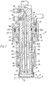
- the molding device of the invention comprises a support 2 and a molding tool generally shown at 4 and disposed above the support 2.
- the support 2 has a substantially flat top surface 6.
- an inverted closure shell 10 having a deposit of liner material 8 on its top panel 12 is conveyed to the top surface 6 of the support 2 by a conveyor mechanism (not shown).
- the container closure shell 10 may be of any conventional shape. For example, it may be fabricated from an aluminium- base alloy sheet, tin-plate or a chromate-treated steel sheet to provide a circular top panel 12 and a cylindrical skirt 13.
- the shape of the deposit of liner material 8 which has been supplied to the top panel 12 may be of any desired shape.
- the liner material 8 be deposited as an annulus near the periphery of panel 12 by such a method as is described in European Patent Publication No. 0012314, or the liner material 8 be prefabricated by such a method as is described in European Patent Application No. 80301920.7 so that a greater part thereof is positioned annularly on the peripheral edge portion of the inside of the top panel 12.
- the molding tool shown generally at 4, has a main body 14, a centre punch 16, an annular bushing 18, and in the illustrated embodiment, an annular position setting sleeve 20 as well for limiting outward flow of the liner material.
- the centre punch 16 is threaded to the main body 14 at 22.
- flow and return passages 24, 26 for cooling fluid (or heating fluid) such as water.
- these passages are constructed so that, as shown by arrows in Figure 1, a cooling fluid (or heating fluid) is introduced into passage 24 through an inlet portion 28, caused to flow into the discharge passage 26 through holes 30 provided at the lower end of the introduction passage 24, and finally discharged from an outlet portion 32.
- the annular bushing 18 is arranged around the centre punch in such a way that it can travel through a predetermined distance.
- the sleeve 20 is disposed externally of the annular bushing 18 so that it can travel through a predetermined range in relation to the main body.
- a resilient means 36 consisting of a compression coil spring, is interposed between the upper end of the sleeve 20 and the lower surface of an annular member 34 (the annular member 34 will be described in greater detail later) fixed to the main body 14, so that the annular position setting sleeve 20 is urged downwardly relative to the main body 14 by the action of the spring means 36.
- the downward movement of the sleeve 20 is limited by contact of a stop ring 38 secured in sleeve 20, with arms 40 projecting at intervals circumferentially from the centre punch 16.
- a resilient means 46 consisting of a compression coil spring, is interposed between a shoulder 42 formed on the lower inside surface of the sleeve 20 and a flange portion 44 at the upper end of the annular bushing 18, so that the annular bushing 18 is resiliently urged upwardly relative to the sleeve 20, and therefore also relative to the main body 14.
- the upward movement of the annular bushing 18 is limited (as shown in Figure 1) by the abutting of the upper end of the annular bushing 18 against the lower end of a tubular member 48.
- the tubular member 48 will be described further hereinbelow.
- the member 48 has formed therein a plurality of slots 50 (only one of which is shown in Figure 1) through which the arms 40 of the centre punch 16 project.
- the molding device of the invention further includes a mechanism (not shown) of any suitable form known per se for raising and lowering the main body 14 of the molding tool 4 and the support relative to each other.
- the molding tool 4 and support 2 may travel around a common axis and the vertical movement of one or both may result from following a stationary cam track.
- the molding device constructed in accordance with this invention should include a mechanism for selectively lowering the annular bushing 18 as required against the resistance of the resilient spring means 46.
- the annular bushing-lowering mechanism may be of a suitable form which can perform the aforesaid operation.
- the annular bushing-lowering mechanism shown generally at 52 consists of a hydraulic cylinder 54 attached to the main body 14 of the molding tool and a piston 56.
- the annular cylinder 54 of the hydraulic cylinder mechanism consists of the main body 14 of the molding device 4, an inverted cup-like member 58, threaded to the main body 14 at 60 and an annular member 34 threaded to the lower end of the member 58 at 62.
- the piston 56 has a head portion 56a slidably received within the cylinder 54 and a rod portion 56b projecting downwardly between the main body 14 and the inner circumferential surface of the annular member 34.
- An inlet port 64 is provided for introducing an actuating fluid such as compressed air or a pressurised oil into the cylinder 54.
- an annular buffer 66 formed of a suitable elastic material, is provided on the upper surface of the annular member 34 to limit downward travel of the piston.
- the mechanism 52 Before entry of the molding tool 4 into the container closure shell 10, the mechanism 52 is in a rest position (as shown in Figure 1) and the annular bushing 18 is held at its most elevated position with respect to the main body 14 by the action of the spring member 46.
- the sleeve 20, on the other hand, is held at its lowest position with respect to the main body 14 by the action of the spring means 36. It is important that in this position the lower end of the annular bushing 18 should be above the lower end of the centre punch 16 and the lower end of the annular position setting sleeve 20 at a sufficient distance. Conveniently, the lower end of the sleeve 20 is slightly below the lower end of the centre punch 16.
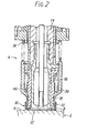
- the sleeve 20 As the main body 14 of the molding tool 4 descends in relation to support 2, the lower end of the sleeve 20 comes into contact with the top panel 12 at a position at which the lower end of the sleeve 20 is close to, or in contact with, the periphery of the annular liner material 8 positioned as shown in Figure 2. In addition to confining the liner material 8 to prevent radial outward flow, the sleeve 20 also performs the function of centering the shell 10 with respect to the molding tool 4.
- the centre punch 16 is brought into abutment with the top panel 12 of the shell 10, (or with the liner material 8 when it is present in a central portion of the panel 12) at a position at which the lower end of the centre punch 16 is close to, or in contact with, the inner circumference of the annular liner material 8.
- the motion of the main body 14 of the molding tool 4 towards support 2 is halted.
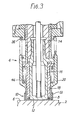
- the mechanism 52 is actuated by the admission of a pressurised fluid into the cylinder 54 in timed relationship with the movement of the body 14 in a manner well understood per se.
- a pressurised fluid is introduced into the cylinder 54 through the inlet port 64, the piston 56 is caused to descend to the position shown in Figure 4, to press the lower end of the bushing 18 against the annular liner material 8.
- the liner material 8 is molded into a desired shape defined by the shape of the lower end of the annular bushing 18.
- the annular bushing 18 is held at its most elevated position with respect to the main body 14 by spring 46, and the lower end of the annular bushing is positioned sufficiently above the lower end of the centre punch 16 and the lower end of the sleeve 20.
- the lower end of the sleeve 20 and the lower end of the centre punch 16 abut the inside surface of the top panel 12 of the shell 10 outwardly and inwardly of the liner material 8 respectively thereby restraining radially outward and inward flow of the liner material 8 positioned between them. It is only after this restraint has been imposed that the annular bushing 18 descends and is pressed against the liner material 8. Accordingly, the liner material 8 is accurately molded into the desired shape without flowing radially outwardly and inwardly.
- the molding tool 4 includes sleeve 20 in addition to the centre punch 16 and the annular bushing 18.
- the sleeve 20 may be omitted when the construction of the device insures that the shell 10 is accurately centred on the support 2 in relation to the tool 4 and the peripheral surface of the annular bushing 18 fits the inner circumferential surface of the skirt 13 very closely to prevent the liner material 8 from flowing radially outwardly and upwardly along the surface of the skirt 13.
- the lower end portion of the annular position setting sleeve 20 can be made shorter than that shown in the drawings so that even in the positions shown in Figures 3 and 4, the lower end of the annular position setting sleeve 20 of the molding tool 4 does not contact the inside surface of the top panel 12 of the shell 10 but is located slightly above it.
- the main body 14 of the molding tool 4 is raised in relation to support 2, thereby moving the lower end of the molding tool 4 away from the shell 10. Desirably, this operation is carried out by the following procedure.
- the port 64 Prior to raising main body 14 of the molding tool 4, the port 64 is switched to exhaust to release fluid pressure acting on piston 56. As a result, (as shown in Figure 5), the action of the spring 46 causes the piston 56 to rise and the annular bushing 18 is returned to its raised position with respect to the main body 14. Hence, the pressure of the annular bushing 18 on the liner material 8 is released. Then, the main body 14 of the molding tool 4 is raised sufficiently in relation to support 2 to lift the lower end of the molding tool 4 completely out of the shell 10. Then, the closure shell 10 is carried away from the top surface 6 of the support 2. Then, pressurised fluid is admitted into the cylinder 54 through the port 64 to actuate the mechanism 52 for lowering the annular bushing 18.
- the annular bushing 18 when after completely releasing the molding tool 4 from the inside of the shell 10, the annular bushing 18 is again lowered and raised in the above-mentioned manner, the inner edge of the sleeve 20 and the outer edge of the centre punch 16 act like a knife edge against the edges of the lower end of the annular bushing 18 while the annular bushing 18 rises. Consequently, the liner material residues adhering to the edges of the annular bushing 18 are removed.
- the spring 46 is interposed between the sleeve 20 and the annular bushing 18 to urge the annular bushing 18 upwardly relative to the main body 14.
- the cylinder mechanism composed of the cylinder 54 and the piston 56 which is single-acting may be changed to a double-acting type so that the double-acting cylinder mechanism may serve both as the mechanism for lowering the annular bushing 18 as required and as the means for raising the annular bushing 18 upwardly relative to the main body 14.
Landscapes
- Engineering & Computer Science (AREA)
- Mechanical Engineering (AREA)
- Chemical & Material Sciences (AREA)
- Composite Materials (AREA)
- Casting Or Compression Moulding Of Plastics Or The Like (AREA)
Applications Claiming Priority (2)
| Application Number | Priority Date | Filing Date | Title |
|---|---|---|---|
| JP3468580A JPS56133144A (en) | 1980-03-21 | 1980-03-21 | Pressure molding device for pressure molding liner inside ceiling of receptacle lid sheel |
| JP34685/80 | 1980-03-21 |
Publications (3)
| Publication Number | Publication Date |
|---|---|
| EP0037651A2 true EP0037651A2 (fr) | 1981-10-14 |
| EP0037651A3 EP0037651A3 (en) | 1982-08-11 |
| EP0037651B1 EP0037651B1 (fr) | 1985-12-27 |
Family
ID=12421251
Family Applications (1)
| Application Number | Title | Priority Date | Filing Date |
|---|---|---|---|
| EP81301107A Expired EP0037651B1 (fr) | 1980-03-21 | 1981-03-17 | Dispositif de moulage d'un joint d'étanchéité à l'intérieur de la surface supérieure d'une fermeture |
Country Status (8)
| Country | Link |
|---|---|
| US (1) | US4388058A (fr) |
| EP (1) | EP0037651B1 (fr) |
| JP (1) | JPS56133144A (fr) |
| AU (1) | AU546798B2 (fr) |
| DE (2) | DE3173282D1 (fr) |
| ES (1) | ES257003Y (fr) |
| MX (1) | MX151671A (fr) |
| ZA (1) | ZA811873B (fr) |
Cited By (3)
| Publication number | Priority date | Publication date | Assignee | Title |
|---|---|---|---|---|
| EP0654342A1 (fr) * | 1993-10-14 | 1995-05-24 | Owens-Illinois Closure Inc. | Procédé et dispositif pour moulage par compression des revêtements d'étanchéité |
| EP0838326A1 (fr) * | 1996-10-24 | 1998-04-29 | SACMI COOPERATIVA MECCANICI IMOLA S.c.r.l. | Appareil pour mouler un joint d'étanchéité plastique à l'intérieur d'une capsule pour fermer un récipient |
| CN1038958C (zh) * | 1992-06-01 | 1998-07-01 | 履带拖拉机股份有限公司 | 利用阀门机构作用的发动机制动 |
Families Citing this family (11)
| Publication number | Priority date | Publication date | Assignee | Title |
|---|---|---|---|---|
| US5036581A (en) * | 1989-09-29 | 1991-08-06 | Weiler Engineering, Inc. | Dry cell battery casing processing |
| US5259745A (en) * | 1990-06-20 | 1993-11-09 | Japan Crown Cork Co., Ltd. | Device for forming annular liner |
| JP3062829B2 (ja) * | 1991-02-13 | 2000-07-12 | 日本クラウンコルク株式会社 | 環状ライナー成形装置 |
| US5332381A (en) * | 1993-02-22 | 1994-07-26 | Zapata Technologies, Inc. | Two piece crown liner punch |
| IT1311066B1 (it) * | 1999-12-23 | 2002-02-28 | Sacmi | Metodo per decorare la sommita' della capsula di chiusura di unrecipiente. |
| US6516548B2 (en) | 2001-01-22 | 2003-02-11 | Quick Point, Inc. | Injection molded container and process for making same |
| US6848894B2 (en) * | 2001-02-27 | 2005-02-01 | Paragon Trade Brands, Inc. | Absorbent article, method and apparatus for preparing same |
| US20050113791A1 (en) * | 2003-11-24 | 2005-05-26 | Kimberly-Clark Worldwide, Inc. | Zoned absorbent structures and process for producing same |
| US7306108B2 (en) | 2004-04-13 | 2007-12-11 | Berry Plastics Corporation | Closure with vents for venting during molding of a liner, method of forming a liner in a closure, and device for forming a liner in a closure |
| DE102009040802B4 (de) * | 2009-08-28 | 2013-09-12 | Saeta Gmbh & Co. Kg | Verfahren und Vorrichtung zum Aufbringen einer Dichtungsmasse auf eine Fläche |
| KR102523951B1 (ko) * | 2021-11-08 | 2023-04-19 | 김대성 | 폴라이트 패킹 자동 부착장치 |
Family Cites Families (17)
| Publication number | Priority date | Publication date | Assignee | Title |
|---|---|---|---|---|
| US2391341A (en) * | 1943-11-23 | 1945-12-18 | Continental Can Co | Machine for applying sealing compound to container ends |
| US2823422A (en) * | 1950-11-08 | 1958-02-18 | Continental Can Co | Manufacture of closure seals having formed cushion pads therein |
| US2881475A (en) * | 1956-02-24 | 1959-04-14 | Crown Cork & Seal Co | Apparatus for applying plastic liners to closures |
| BE627697A (fr) * | 1962-07-23 | |||
| US3366723A (en) * | 1964-07-24 | 1968-01-30 | Armstrong Cork Co | Method for forming a liner on a closure |
| US3343211A (en) * | 1966-10-12 | 1967-09-26 | Rosen And Strickman | Apparatus for forming ring-shaped extrudates |
| US3547746A (en) * | 1967-07-27 | 1970-12-15 | Stanley Works | Molded embossed sealing liner having indicia |
| GB1200984A (en) * | 1968-05-10 | 1970-08-05 | Grace W R & Co | Improvements relating to moulding apparatus and method |
| US3621530A (en) * | 1969-06-30 | 1971-11-23 | Anchor Hocking Corp | Means for molding closure cap gaskets |
| DE2035467C3 (de) * | 1969-07-29 | 1979-06-13 | Ettore Imola Busi (Italien) | Vorrichtung zum Formen von inneren Belägen aus thermoplastischem Kunststoff in Verschlußkapseln o.dgl |
| US3807924A (en) * | 1971-04-10 | 1974-04-30 | A Mingotti | Volumetric injector particularly for delivering batches of fluid plastics material |
| US3827843A (en) * | 1972-01-26 | 1974-08-06 | Sycamore Mfg Co Inc | Apparatus for lining bottle crowns with thermoplastic material |
| JPS517196A (en) * | 1974-07-05 | 1976-01-21 | Tanabe Seiyaku Co | Shoyumoromino seiho |
| JPS5432783Y2 (fr) * | 1975-06-24 | 1979-10-11 | ||
| IL51582A (en) * | 1976-03-11 | 1979-05-31 | Crown Cork Japan | Cap and method for sealing containers therewith |
| JPS593141B2 (ja) * | 1978-08-28 | 1984-01-23 | 大阪永柳工業株式会社 | パッキン付瓶蓋の製造装置 |
| JPS5577523A (en) * | 1978-12-06 | 1980-06-11 | Japan Crown Cork Co Ltd | Method of and apparatus for forming liner in cover for vessel |
-
1980
- 1980-03-21 JP JP3468580A patent/JPS56133144A/ja active Granted
-
1981
- 1981-03-17 EP EP81301107A patent/EP0037651B1/fr not_active Expired
- 1981-03-17 DE DE8181301107T patent/DE3173282D1/de not_active Expired
- 1981-03-17 MX MX186408A patent/MX151671A/es unknown
- 1981-03-19 DE DE19818108052U patent/DE8108052U1/de not_active Expired
- 1981-03-20 ZA ZA00811873A patent/ZA811873B/xx unknown
- 1981-03-20 AU AU68579/81A patent/AU546798B2/en not_active Ceased
- 1981-03-20 ES ES1981257003U patent/ES257003Y/es not_active Expired
- 1981-03-23 US US06/246,641 patent/US4388058A/en not_active Expired - Fee Related
Cited By (5)
| Publication number | Priority date | Publication date | Assignee | Title |
|---|---|---|---|---|
| CN1038958C (zh) * | 1992-06-01 | 1998-07-01 | 履带拖拉机股份有限公司 | 利用阀门机构作用的发动机制动 |
| EP0654342A1 (fr) * | 1993-10-14 | 1995-05-24 | Owens-Illinois Closure Inc. | Procédé et dispositif pour moulage par compression des revêtements d'étanchéité |
| AU677861B2 (en) * | 1993-10-14 | 1997-05-08 | Rexam Closure Systems Inc. | Method and apparatus for compression molding closure liners |
| EP0838326A1 (fr) * | 1996-10-24 | 1998-04-29 | SACMI COOPERATIVA MECCANICI IMOLA S.c.r.l. | Appareil pour mouler un joint d'étanchéité plastique à l'intérieur d'une capsule pour fermer un récipient |
| US6007315A (en) * | 1996-10-24 | 1999-12-28 | Sacmi Cooperative Meccanici Imola S.C.R.L. | Apparatus for molding a plastic seal inside a closure for closing a container |
Also Published As
| Publication number | Publication date |
|---|---|
| EP0037651B1 (fr) | 1985-12-27 |
| JPS56133144A (en) | 1981-10-19 |
| EP0037651A3 (en) | 1982-08-11 |
| DE3173282D1 (en) | 1986-02-06 |
| US4388058A (en) | 1983-06-14 |
| AU546798B2 (en) | 1985-09-19 |
| ES257003Y (es) | 1982-04-16 |
| AU6857981A (en) | 1981-09-24 |
| ZA811873B (en) | 1982-05-26 |
| ES257003U (es) | 1981-10-16 |
| DE8108052U1 (de) | 1982-01-21 |
| MX151671A (es) | 1985-01-30 |
| JPS6358088B2 (fr) | 1988-11-15 |
Similar Documents
| Publication | Publication Date | Title |
|---|---|---|
| EP0037651B1 (fr) | Dispositif de moulage d'un joint d'étanchéité à l'intérieur de la surface supérieure d'une fermeture | |
| US4346743A (en) | Product bag for aerosol container and method of utilizing the same to facilitate filling with propellant | |
| US4750533A (en) | Filling valve for counterpressure filling of cans | |
| JPH082158Y2 (ja) | 缶等の容器に使用される充填バルブ機構 | |
| GB2141052A (en) | Forming end panels for two-piece cans in double acting press | |
| US5145008A (en) | Filling valve for counterpressure filling of cans | |
| US3563287A (en) | Machines for filling beer kegs and like containers | |
| EP0039196B1 (fr) | Dispositif pour mouler un disque d'étanchéité servant à garnir le fond d'une capsule de fermeture d'un récipient | |
| US2859575A (en) | Apparatus for closing and sealing containers | |
| US3385249A (en) | Method of making containers | |
| US4088730A (en) | Method and apparatus for forming closure inserts | |
| US4986318A (en) | Filling valve for counterpressure filling of cans | |
| US3336720A (en) | Method of and apparatus for filling aerosol containers | |
| US4177546A (en) | Apparatus for inserting a resilient band on a container | |
| EP0364356B1 (fr) | Moule pour la fabrication par compression des roues composites renforcées par des fibres | |
| US5341667A (en) | Container bottom wall reforming apparatus and method | |
| US3958910A (en) | Apparatus for forming closure inserts | |
| US5332381A (en) | Two piece crown liner punch | |
| ES2000495A6 (es) | Aparato para el gaseado y la obtencion de un envase | |
| US3571891A (en) | Press feed and ejector apparatus | |
| US4362254A (en) | Closure and container neck structure therefor | |
| GB2131334A (en) | Tapered two-piece metal containers | |
| US2975575A (en) | Apparatus for securing and sealing a closure cap to a receptacle | |
| US4653249A (en) | Telescopic filling adapter for bottle filling machines | |
| CA1124477A (fr) | Methode de soudage d'un dispositif stabilisateur d'un contenant |
Legal Events
| Date | Code | Title | Description |
|---|---|---|---|
| PUAI | Public reference made under article 153(3) epc to a published international application that has entered the european phase |
Free format text: ORIGINAL CODE: 0009012 |
|
| AK | Designated contracting states |
Designated state(s): DE FR GB IT NL SE |
|
| PUAL | Search report despatched |
Free format text: ORIGINAL CODE: 0009013 |
|
| AK | Designated contracting states |
Designated state(s): DE FR GB IT NL SE |
|
| 17P | Request for examination filed |
Effective date: 19830124 |
|
| ITF | It: translation for a ep patent filed | ||
| GRAA | (expected) grant |
Free format text: ORIGINAL CODE: 0009210 |
|
| AK | Designated contracting states |
Designated state(s): DE FR GB IT NL SE |
|
| REF | Corresponds to: |
Ref document number: 3173282 Country of ref document: DE Date of ref document: 19860206 |
|
| ET | Fr: translation filed | ||
| PLBE | No opposition filed within time limit |
Free format text: ORIGINAL CODE: 0009261 |
|
| STAA | Information on the status of an ep patent application or granted ep patent |
Free format text: STATUS: NO OPPOSITION FILED WITHIN TIME LIMIT |
|
| 26N | No opposition filed | ||
| ITTA | It: last paid annual fee | ||
| PGFP | Annual fee paid to national office [announced via postgrant information from national office to epo] |
Ref country code: GB Payment date: 19940308 Year of fee payment: 14 |
|
| PGFP | Annual fee paid to national office [announced via postgrant information from national office to epo] |
Ref country code: FR Payment date: 19940310 Year of fee payment: 14 Ref country code: DE Payment date: 19940310 Year of fee payment: 14 |
|
| PGFP | Annual fee paid to national office [announced via postgrant information from national office to epo] |
Ref country code: SE Payment date: 19940316 Year of fee payment: 14 |
|
| PGFP | Annual fee paid to national office [announced via postgrant information from national office to epo] |
Ref country code: NL Payment date: 19940331 Year of fee payment: 14 |
|
| EAL | Se: european patent in force in sweden |
Ref document number: 81301107.9 |
|
| PG25 | Lapsed in a contracting state [announced via postgrant information from national office to epo] |
Ref country code: GB Effective date: 19950317 |
|
| PG25 | Lapsed in a contracting state [announced via postgrant information from national office to epo] |
Ref country code: SE Effective date: 19950318 |
|
| PG25 | Lapsed in a contracting state [announced via postgrant information from national office to epo] |
Ref country code: NL Effective date: 19951001 |
|
| GBPC | Gb: european patent ceased through non-payment of renewal fee |
Effective date: 19950317 |
|
| PG25 | Lapsed in a contracting state [announced via postgrant information from national office to epo] |
Ref country code: FR Free format text: LAPSE BECAUSE OF NON-PAYMENT OF DUE FEES Effective date: 19951130 |
|
| NLV4 | Nl: lapsed or anulled due to non-payment of the annual fee |
Effective date: 19951001 |
|
| PG25 | Lapsed in a contracting state [announced via postgrant information from national office to epo] |
Ref country code: DE Effective date: 19951201 |
|
| EUG | Se: european patent has lapsed |
Ref document number: 81301107.9 |
|
| REG | Reference to a national code |
Ref country code: FR Ref legal event code: ST |