EP0037665B1 - Verfahren und Vorrichtung zur Gewinnung von Acetylen - Google Patents
Verfahren und Vorrichtung zur Gewinnung von Acetylen Download PDFInfo
- Publication number
- EP0037665B1 EP0037665B1 EP81301205A EP81301205A EP0037665B1 EP 0037665 B1 EP0037665 B1 EP 0037665B1 EP 81301205 A EP81301205 A EP 81301205A EP 81301205 A EP81301205 A EP 81301205A EP 0037665 B1 EP0037665 B1 EP 0037665B1
- Authority
- EP
- European Patent Office
- Prior art keywords
- acetylene
- solvent
- heat exchanger
- stream
- vapor
- Prior art date
- Legal status (The legal status is an assumption and is not a legal conclusion. Google has not performed a legal analysis and makes no representation as to the accuracy of the status listed.)
- Expired
Links
- HSFWRNGVRCDJHI-UHFFFAOYSA-N alpha-acetylene Natural products C#C HSFWRNGVRCDJHI-UHFFFAOYSA-N 0.000 title claims description 46
- 125000002534 ethynyl group Chemical group [H]C#C* 0.000 title claims description 46
- 238000011084 recovery Methods 0.000 title claims description 29
- 239000002904 solvent Substances 0.000 claims description 34
- 239000007788 liquid Substances 0.000 claims description 21
- CSCPPACGZOOCGX-UHFFFAOYSA-N Acetone Chemical compound CC(C)=O CSCPPACGZOOCGX-UHFFFAOYSA-N 0.000 claims description 18
- 239000006096 absorbing agent Substances 0.000 claims description 17
- 238000000034 method Methods 0.000 claims description 17
- 230000008569 process Effects 0.000 claims description 17
- VGGSQFUCUMXWEO-UHFFFAOYSA-N Ethene Chemical compound C=C VGGSQFUCUMXWEO-UHFFFAOYSA-N 0.000 claims description 14
- 239000005977 Ethylene Substances 0.000 claims description 14
- 239000000203 mixture Substances 0.000 claims description 12
- ZMXDDKWLCZADIW-UHFFFAOYSA-N N,N-Dimethylformamide Chemical compound CN(C)C=O ZMXDDKWLCZADIW-UHFFFAOYSA-N 0.000 claims description 9
- 239000007791 liquid phase Substances 0.000 claims description 9
- ZWEHNKRNPOVVGH-UHFFFAOYSA-N 2-Butanone Chemical compound CCC(C)=O ZWEHNKRNPOVVGH-UHFFFAOYSA-N 0.000 claims description 6
- OKKJLVBELUTLKV-UHFFFAOYSA-N Methanol Chemical group OC OKKJLVBELUTLKV-UHFFFAOYSA-N 0.000 claims description 6
- 239000012808 vapor phase Substances 0.000 claims description 6
- 238000001816 cooling Methods 0.000 claims description 5
- 238000010438 heat treatment Methods 0.000 claims description 5
- YEJRWHAVMIAJKC-UHFFFAOYSA-N 4-Butyrolactone Chemical compound O=C1CCCO1 YEJRWHAVMIAJKC-UHFFFAOYSA-N 0.000 claims description 4
- 238000000926 separation method Methods 0.000 claims description 4
- 239000004215 Carbon black (E152) Substances 0.000 claims description 3
- 238000010521 absorption reaction Methods 0.000 claims description 3
- 238000009835 boiling Methods 0.000 claims description 3
- 238000005336 cracking Methods 0.000 claims description 3
- 229930195733 hydrocarbon Natural products 0.000 claims description 3
- 150000002430 hydrocarbons Chemical class 0.000 claims description 3
- 238000010792 warming Methods 0.000 claims description 3
- 229930188620 butyrolactone Natural products 0.000 claims description 2
- 239000012071 phase Substances 0.000 claims 1
- 239000007789 gas Substances 0.000 description 7
- 239000003507 refrigerant Substances 0.000 description 6
- 238000013461 design Methods 0.000 description 4
- 238000010586 diagram Methods 0.000 description 3
- 230000009467 reduction Effects 0.000 description 3
- 238000013459 approach Methods 0.000 description 2
- 238000012545 processing Methods 0.000 description 2
- QQONPFPTGQHPMA-UHFFFAOYSA-N propylene Natural products CC=C QQONPFPTGQHPMA-UHFFFAOYSA-N 0.000 description 2
- 125000004805 propylene group Chemical group [H]C([H])([H])C([H])([*:1])C([H])([H])[*:2] 0.000 description 2
- 238000005057 refrigeration Methods 0.000 description 2
- 239000006200 vaporizer Substances 0.000 description 2
- 230000009471 action Effects 0.000 description 1
- XAGFODPZIPBFFR-UHFFFAOYSA-N aluminium Chemical compound [Al] XAGFODPZIPBFFR-UHFFFAOYSA-N 0.000 description 1
- 229910052782 aluminium Inorganic materials 0.000 description 1
- 230000008901 benefit Effects 0.000 description 1
- 230000008859 change Effects 0.000 description 1
- 239000000470 constituent Substances 0.000 description 1
- 239000000498 cooling water Substances 0.000 description 1
- 230000003247 decreasing effect Effects 0.000 description 1
- 238000011161 development Methods 0.000 description 1
- 230000008030 elimination Effects 0.000 description 1
- 238000003379 elimination reaction Methods 0.000 description 1
- 239000012530 fluid Substances 0.000 description 1
- 238000004064 recycling Methods 0.000 description 1
- 238000012546 transfer Methods 0.000 description 1
- XLYOFNOQVPJJNP-UHFFFAOYSA-N water Substances O XLYOFNOQVPJJNP-UHFFFAOYSA-N 0.000 description 1
Images

Classifications
-
- B—PERFORMING OPERATIONS; TRANSPORTING
- B01—PHYSICAL OR CHEMICAL PROCESSES OR APPARATUS IN GENERAL
- B01D—SEPARATION
- B01D53/00—Separation of gases or vapours; Recovering vapours of volatile solvents from gases; Chemical or biological purification of waste gases, e.g. engine exhaust gases, smoke, fumes, flue gases, aerosols
- B01D53/14—Separation of gases or vapours; Recovering vapours of volatile solvents from gases; Chemical or biological purification of waste gases, e.g. engine exhaust gases, smoke, fumes, flue gases, aerosols by absorption
- B01D53/1493—Selection of liquid materials for use as absorbents
-
- B—PERFORMING OPERATIONS; TRANSPORTING
- B01—PHYSICAL OR CHEMICAL PROCESSES OR APPARATUS IN GENERAL
- B01D—SEPARATION
- B01D53/00—Separation of gases or vapours; Recovering vapours of volatile solvents from gases; Chemical or biological purification of waste gases, e.g. engine exhaust gases, smoke, fumes, flue gases, aerosols
- B01D53/14—Separation of gases or vapours; Recovering vapours of volatile solvents from gases; Chemical or biological purification of waste gases, e.g. engine exhaust gases, smoke, fumes, flue gases, aerosols by absorption
- B01D53/1487—Removing organic compounds
-
- C—CHEMISTRY; METALLURGY
- C07—ORGANIC CHEMISTRY
- C07C—ACYCLIC OR CARBOCYCLIC COMPOUNDS
- C07C7/00—Purification; Separation; Use of additives
- C07C7/11—Purification; Separation; Use of additives by absorption, i.e. purification or separation of gaseous hydrocarbons with the aid of liquids
-
- Y—GENERAL TAGGING OF NEW TECHNOLOGICAL DEVELOPMENTS; GENERAL TAGGING OF CROSS-SECTIONAL TECHNOLOGIES SPANNING OVER SEVERAL SECTIONS OF THE IPC; TECHNICAL SUBJECTS COVERED BY FORMER USPC CROSS-REFERENCE ART COLLECTIONS [XRACs] AND DIGESTS
- Y02—TECHNOLOGIES OR APPLICATIONS FOR MITIGATION OR ADAPTATION AGAINST CLIMATE CHANGE
- Y02P—CLIMATE CHANGE MITIGATION TECHNOLOGIES IN THE PRODUCTION OR PROCESSING OF GOODS
- Y02P30/00—Technologies relating to oil refining and petrochemical industry
- Y02P30/40—Ethylene production
Definitions
- the present invention relates to an improved acetylene recovery process and apparatus therefor and, more particularly, to use in connection with the interstage processing of acetylene-containing gas in a three-column acetylene separation recovery unit.
- the three-column acetylene recovery unit comprises an acetylene absorber column, a vent column and an acetylene still column.
- the three-column acetylene recovery unit has been designed to require the consumption of relatively large quantities of utility steam, refrigerant and cooling water.
- Such units require the consumption of considerable external energy and result in a considerable increase in over-all operating cost of the system.
- an improved process for the recovery of acetylene from a feed gas stream containing acetylene and ethylene and produced by the cracking of hydrocarbon feedstock.
- Such process comprises the steps of: contacting said gas stream in a contacting zone under pressure with an acetylene solvent in a quantity sufficient for the absorption of substantially all of the acetylene and some of the ethylene of said feed gas stream to form a loaded solvent solution; warming and partially boiling said loaded solvent solution by passing through a first stream conduit of a zone having a plurality of non-interconnecting stream con - duits passing therethrough in heat exchange thermal contact; separating the resulting liquid/vapor mixture and recycling said vapor phase to the liquid discharge region of said contacting zone; passing the liquid phase to a second stream conduit of said zone having a plurality of non-interconnecting stream conduits passing therethrough in heat exchange thermal contact, thereby permitting the temperature thereof to drop substantially before said liquid phase passes on to a downstream further separation step for the removal of further pur
- the present invention provides an improved apparatus for the improved process.
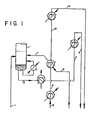
- the conventional or prior art process employs apparatus as shown in Fig. 1 of the drawings.
- the ethylene and acetylene gas mixture (1) is fed to the lower portion of an acetylene absorber column at a point below the bottom tray and above the liquid level in the column.
- the process of the invention is not limited to the use of any particular acetylene solvent and any solvent which is capable of dissolving acetylene more selectively than ethylene and other constituent gases may be employed.
- solvents comprise, for example, methanol, dimethylformamide, methyl ethyl ketone, butyrolactone and acetone. Dimethylformamide has been found to be a preferred solvent.
- Liquid, in the form of loaded solvent (2), is passed from the bottom of the acetylene absorber column through two independent vent feed coolers before passage (3, 4) to the downstream vent column.
- Warm denuded solvent (8) is similarly passed through two independent coolers before passage (9. 10, 5) from the interstage system.
- Liquid recycle (6) is passed through a recycle vaporizer before introduction (7) into the bottom of the acetylene absorber column.
- a portion of the liquid from the bottom of the acetylene absorber column is also steam vaporized and reintroduced into the area between the bottom tray and the liquid surface within the acetylene absorber column.
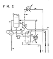
- Fig. 2 of the drawings The preferable apparatus for practicing the process of the present invention is shown in Fig. 2 of the drawings.
- an optional inlet gas feed preheater is provided prior to the introduction of feed into the bottom of the acetylene absorber column as shown in Fig. 2.
- the feed (11) enters the absorber at 2067 kPa (300 psia) as vapor at 9°C. at the rate of about 56 tonnes (123,000 pounds) per hour (12).
- the objective of the optional feed preheater is to recover refrigerant.
- the composition of the pre-heated feed is 0.9886 mole fraction ethylene and 0.0114 mole fraction acetylene. In the column, .
- the liquid flows to the bottom of the absorber column and exits (13) through an optional pump at a flow rate of 67 tonnes (148,000 pounds) per hour, temperature of approximately -8°C. and a composition of 0.0358 mole fraction acetylene, 0.3132 mole fraction ethylene and 0.6505 acetone mole fraction.
- This mixture is warmed and partially boiled in the recovery heat exchanger passage A and flows as a liquid/vapor mix (14) to the trim heater kettle.
- the vapor (15) flows overhead and the liquid (16) is further heated to 90°C. using steam as a heating medium.
- the additional vapor generated in the trim heater flows with the flashed vapor phase to the base of the absorber column.
- the liquid composition (mole fraction) is now 0.0249 acetylene, 0.0854 ethylene and 0.8901 acetone and the flow rate is 54 tonnes (119,000 pounds) per hour.
- This liquid flows to passage B of the recovery heat exchanger where it is cooled, thereby providing heat for exchange to passage A.
- the flow rates and compositions do not change, but the temperature drops to 30°C. This temperature is governed by the critical design of the heat exchanger as is well known to those skilled in this design art.
- the liquid (17) flows to the ethylene vent column for further processing.
- the warm denuded solvent (21) is chilled to -33°C. in four stages: the first stage is passage C of the recovery heat exchanger, the pure acetone solvent at 78°C. flowing at 53 tonnes (118,000 pounds) per hour is cooled to +5.3°C. (22) (the sensible heat being transferred to passage A); the solvent being further cooled to -14.5°C. (23) in the optional feed preheater and then to -246°C. (24) in the optional recycle vaporizer; and finally cooled to -33°C. (18) using the refrigerant action of the solvent chiller.
- the liquid recycle (19, 20) is treated as before.
- a brazed aluminum plate and fin type heat exchanger is preferably employed as the recovery heat exchanger.
- Such a heat exchanger employs aligned plate blocks having internal set of fluid channels, the plate blocks being successively brazed to each other to provide the required thermal contact.
- Such a heat exchanger provides for the development of a thermal gradient across its transverse section, i.e., the section shown schematically in Fig. 2 of the drawings.
- Other suitable equivalent types of heat exchangers may, however, be operably employed as the recovery heat exchanger in the apparatus aspect of the present invention.
- vent feed cooler and the vent feed chiller of the conventional system of Fig. 1 have been eliminated.
- the need for the conventional process cold (-27°C.) vent column feed is eliminated.
- the vent column reboiler heat requirement (and consequently column diameter) is decreased.
- Passage C of the recovery heat exchanger contains warm denuded solvent. This passage, like passage B, flows countercurrent to passage A. The denuded solvent exits the recovery heat exchanger at -3°C. where it is then cooled against recycle ethylene and subsequently against propylene refrigerant, thereby eliminating the use of external utility solvent cooler (206-344 kPa; (30-50 psi) propylene refrigerant).
- recovery heat exchanger must be properly designed to take maximum benefit of the available heat.
- the design of the recovery heat exchanger must be nearly true counterflow in order to achieve the optimal operability.
- the recovery heat exchanger shown in the process flow diagram of Fig. 2 and described herein as a plate and fin heat exchanger, is designed for a 5°C. temperature approach on the cold end. Relative equipment/energy costs at the time of the design will dictate the approach temperature and hence exchanger size used.
- a booster pump is shown on the column kettle liquid. Its purpose is to overcome pressure drop in the recovery heat exchanger.
- the pump can be eliminated if the column is elevated or a high liquid level is maintained in the column base. This results in a larger recovery heat exchanger as the required lower pressure drop results in a lower over-all heat transfer coefficient. Relative equipment costs will dictate whether or not the booster pump is used.
- any other counterflow heat exchanger can be substituted.
- the temperatures and pressures shown can be optimized with respect to other portions of the plant.
- the process can be made to function satisfactorily without the trim heater kettle.
- the solvent water cooler (cools solvent from 80 to 45°C.) is bypassed or eliminated.
- the hot solvent is now the only heat source for the acetylene absorber kettle. Very little additional utility or refrigerant consumption results from elimination of the trim heater. However, the system is judged to be more difficult to operate as one degree of freedom is lost.
- Tables I and II set forth respectively data for the operation of a conventional system of prior art (as set forth schematically in Fig. 1 of the drawings) and for the system of the present invention (as schematically shown in Fig. 2 of the drawings).
- the data sets forth the various parameters including stream state, flow temperature and composition values for different streams in the conventional system and the system of the present invention. It is to be noted that such stream data is set forth for ten (10) locations in the conventional system (Table I) and fourteen (14) locations in the system of the present invention (Table II).
Landscapes
- Chemical & Material Sciences (AREA)
- Engineering & Computer Science (AREA)
- Analytical Chemistry (AREA)
- Oil, Petroleum & Natural Gas (AREA)
- Organic Chemistry (AREA)
- General Chemical & Material Sciences (AREA)
- Chemical Kinetics & Catalysis (AREA)
- Water Supply & Treatment (AREA)
- Organic Low-Molecular-Weight Compounds And Preparation Thereof (AREA)
Claims (4)
Applications Claiming Priority (2)
| Application Number | Priority Date | Filing Date | Title |
|---|---|---|---|
| US06/134,948 US4274841A (en) | 1980-03-28 | 1980-03-28 | Acetylene recovery process and apparatus |
| US134948 | 1980-03-28 |
Publications (2)
| Publication Number | Publication Date |
|---|---|
| EP0037665A1 EP0037665A1 (de) | 1981-10-14 |
| EP0037665B1 true EP0037665B1 (de) | 1984-08-01 |
Family
ID=22465742
Family Applications (1)
| Application Number | Title | Priority Date | Filing Date |
|---|---|---|---|
| EP81301205A Expired EP0037665B1 (de) | 1980-03-28 | 1981-03-20 | Verfahren und Vorrichtung zur Gewinnung von Acetylen |
Country Status (5)
| Country | Link |
|---|---|
| US (1) | US4274841A (de) |
| EP (1) | EP0037665B1 (de) |
| JP (1) | JPS56150025A (de) |
| CA (1) | CA1147756A (de) |
| DE (1) | DE3165169D1 (de) |
Families Citing this family (33)
| Publication number | Priority date | Publication date | Assignee | Title |
|---|---|---|---|---|
| DE4037060A1 (de) * | 1990-11-22 | 1992-05-27 | Krupp Koppers Gmbh | Verfahren zur aufarbeitung des sumpfproduktes von extraktivdestillationsprozessen zur gewinnung reiner aromaten |
| RU2146238C1 (ru) * | 1998-05-25 | 2000-03-10 | Новочеркасский завод синтетических продуктов | Способ выделения ацетилена из сбросных газов |
| US8664124B2 (en) | 2005-10-31 | 2014-03-04 | Novellus Systems, Inc. | Method for etching organic hardmasks |
| US8110493B1 (en) | 2005-12-23 | 2012-02-07 | Novellus Systems, Inc. | Pulsed PECVD method for modulating hydrogen content in hard mask |
| US7915166B1 (en) | 2007-02-22 | 2011-03-29 | Novellus Systems, Inc. | Diffusion barrier and etch stop films |
| US8962101B2 (en) | 2007-08-31 | 2015-02-24 | Novellus Systems, Inc. | Methods and apparatus for plasma-based deposition |
| US7820556B2 (en) * | 2008-06-04 | 2010-10-26 | Novellus Systems, Inc. | Method for purifying acetylene gas for use in semiconductor processes |
| US8435608B1 (en) | 2008-06-27 | 2013-05-07 | Novellus Systems, Inc. | Methods of depositing smooth and conformal ashable hard mask films |
| US7955990B2 (en) * | 2008-12-12 | 2011-06-07 | Novellus Systems, Inc. | Method for improved thickness repeatability of PECVD deposited carbon films |
| US8563414B1 (en) | 2010-04-23 | 2013-10-22 | Novellus Systems, Inc. | Methods for forming conductive carbon films by PECVD |
| US9505680B2 (en) | 2011-01-19 | 2016-11-29 | Exxonmobil Chemical Patents Inc. | Method and apparatus for managing the conversion of hydrocarbons into olefins |
| US9868680B2 (en) | 2011-01-19 | 2018-01-16 | Exxonmobil Chemical Patents Inc. | Method and apparatus for converting hydrocarbons into olefins |
| WO2012099673A2 (en) | 2011-01-19 | 2012-07-26 | Exxonmobil Chemical Patents Inc. | Hydrocarbon conversion process |
| US9708231B2 (en) | 2011-01-19 | 2017-07-18 | Exxonmobil Chemical Patents Inc. | Method and apparatus for converting hydrocarbons into olefins using hydroprocessing and thermal pyrolysis |
| US9676681B2 (en) | 2011-01-19 | 2017-06-13 | Exxonmobil Chemical Patents Inc. | Method and apparatus for managing hydrogen content through the conversion of hydrocarbons into olefins |
| US9677014B2 (en) | 2011-01-19 | 2017-06-13 | Exxonmobil Chemical Patents Inc. | Process and apparatus for converting hydrocarbons |
| US9815751B2 (en) | 2011-01-19 | 2017-11-14 | Exxonmobil Chemical Patents Inc. | Hydrocarbon and oxygenate conversion by high severity pyrolysis to make acetylene and ethylene |
| SG191197A1 (en) | 2011-01-19 | 2013-07-31 | Exxonmobil Chem Patents Inc | Method and apparatus for converting hydrocarbons into olefins |
| CA2822285C (en) | 2011-01-19 | 2016-04-26 | Exxonmobil Chemical Patents Inc. | Hydrocarbon conversion process |
| US9708232B2 (en) | 2011-01-19 | 2017-07-18 | Exxonmobil Chemical Patents Inc. | Method and apparatus for converting hydrocarbons into olefins |
| US9505676B2 (en) | 2012-05-03 | 2016-11-29 | Exxonmobil Chemical Patents Inc. | Hydrocarbon conversion process |
| CN104245641B (zh) | 2012-05-18 | 2017-06-16 | 埃克森美孚化学专利公司 | 烃转化方法 |
| SG195494A1 (en) | 2012-05-18 | 2013-12-30 | Novellus Systems Inc | Carbon deposition-etch-ash gap fill process |
| US9362133B2 (en) | 2012-12-14 | 2016-06-07 | Lam Research Corporation | Method for forming a mask by etching conformal film on patterned ashable hardmask |
| US9304396B2 (en) | 2013-02-25 | 2016-04-05 | Lam Research Corporation | PECVD films for EUV lithography |
| US9320387B2 (en) | 2013-09-30 | 2016-04-26 | Lam Research Corporation | Sulfur doped carbon hard masks |
| US9589799B2 (en) | 2013-09-30 | 2017-03-07 | Lam Research Corporation | High selectivity and low stress carbon hardmask by pulsed low frequency RF power |
| JP6975625B2 (ja) * | 2017-11-29 | 2021-12-01 | 大陽日酸株式会社 | 真空浸炭炉用アセチレンガス供給装置及びその供給方法 |
| US11837441B2 (en) | 2019-05-29 | 2023-12-05 | Lam Research Corporation | Depositing a carbon hardmask by high power pulsed low frequency RF |
| CN114342043A (zh) | 2019-08-30 | 2022-04-12 | 朗姆研究公司 | 低压下的高密度、模量和硬度的非晶碳膜 |
| CN115867999A (zh) | 2020-06-06 | 2023-03-28 | 朗姆研究公司 | 用于半导体处理的可移除喷头面板 |
| CN115917039A (zh) | 2020-07-29 | 2023-04-04 | 朗姆研究公司 | 使用起泡器的浓度控制 |
| CN113004942A (zh) * | 2021-03-02 | 2021-06-22 | 太仓市金阳气体有限公司 | 一种安全可控的乙炔生产设备 |
Family Cites Families (10)
| Publication number | Priority date | Publication date | Assignee | Title |
|---|---|---|---|---|
| CA621103A (en) * | 1961-05-30 | F. Palazzo Dominic | Separation of hydrogen-methane mixtures | |
| NL33894C (de) * | 1932-02-11 | |||
| US2146448A (en) * | 1936-05-06 | 1939-02-07 | Du Pont | Acetylene solution |
| US2742102A (en) * | 1947-12-18 | 1956-04-17 | Internat Carbonic Engineering | Process and apparatus for recovering carbon dioxide from exhaust gases |
| US2891633A (en) * | 1956-09-26 | 1959-06-23 | Union Carbide Corp | Acetylene separation system |
| US3098107A (en) * | 1959-05-22 | 1963-07-16 | Linde Eismasch Ag | Method for producing ethylene |
| US3034272A (en) * | 1959-11-23 | 1962-05-15 | Phillips Petroleum Co | Acetylene recovery and purification method |
| US3087310A (en) * | 1959-12-11 | 1963-04-30 | Linde Eismasch Ag | Process for the production of acetylene-free ethylene |
| US4086288A (en) * | 1976-08-16 | 1978-04-25 | Phillips Petroleum Company | Acetylenes removal from olefin streams for alkylation by dimethyl formamide absorption |
| US4184855A (en) * | 1977-12-29 | 1980-01-22 | Union Carbide Corporation | Process for CO2 removal |
-
1980
- 1980-03-28 US US06/134,948 patent/US4274841A/en not_active Expired - Lifetime
-
1981
- 1981-02-20 CA CA000371401A patent/CA1147756A/en not_active Expired
- 1981-03-20 EP EP81301205A patent/EP0037665B1/de not_active Expired
- 1981-03-20 DE DE8181301205T patent/DE3165169D1/de not_active Expired
- 1981-03-27 JP JP4422981A patent/JPS56150025A/ja active Granted
Also Published As
| Publication number | Publication date |
|---|---|
| JPS56150025A (en) | 1981-11-20 |
| CA1147756A (en) | 1983-06-07 |
| US4274841A (en) | 1981-06-23 |
| DE3165169D1 (en) | 1984-09-06 |
| EP0037665A1 (de) | 1981-10-14 |
| JPS617411B2 (de) | 1986-03-06 |
Similar Documents
| Publication | Publication Date | Title |
|---|---|---|
| EP0037665B1 (de) | Verfahren und Vorrichtung zur Gewinnung von Acetylen | |
| EP0099701B1 (de) | Verfahren und Vorrichtung zur Umwandlung von Olefinen in Benzin und Destillat | |
| JP4441117B2 (ja) | エチルベンゼン/スチレン塔のカスケード再沸 | |
| KR100338407B1 (ko) | 올레핀을회수하기위한복합식응축-흡수방법 | |
| JPH083100B2 (ja) | C3▲上+▼炭化水素の分離と回収の方法 | |
| KR20190058627A (ko) | 분해된 가스를 압축하기 위한 스테이지 및 시스템 | |
| KR860001490B1 (ko) | 염수로부터 청수(淸水)를 얻기위한 염수의 증류방법 및 장치 | |
| US4089175A (en) | Process and system for recovery of energy from geothermal brines and other water containing sources by direct contact with a working fluid below the critical pressure | |
| US3026682A (en) | Separation of hydrogen and methane | |
| US4326041A (en) | Process for the catalytic synthesis of methanol | |
| PL172492B1 (pl) | Sposób i urzadzenie do wytwarzania nieoczyszczonego helu PL PL PL PL PL PL PL PL PL | |
| GB1568920A (en) | Separation of methane from crude gases containing methane | |
| US4496381A (en) | Apparatus and method for recovering light hydrocarbons from hydrogen containing gases | |
| US2214790A (en) | Process and apparatus for separating gases | |
| US4137129A (en) | Fractionation process | |
| CN111225726A (zh) | 用于解吸剂回收的方法和设备 | |
| US3796059A (en) | Cryogenic purification of hydrodealkylation and refinery hydrogen off-gas streams | |
| JP2019525107A (ja) | 冷媒通気精留器及び効率増進器 | |
| US5214225A (en) | Dehydrogenation process with improved heat recovery | |
| US3444072A (en) | Method for minimizing hydrogen losses in high pressure processes | |
| US2949494A (en) | Alkylation of hydrocarbons utilizing evaporative cooling | |
| US2894371A (en) | Preventing condensation inside a vortex tube | |
| US5015459A (en) | High pressure-low pressure steam system for extended Claus sulfur recovery plant | |
| US5238540A (en) | Method of obtaining a pure aromatic hydrocarbon from a sump product of an extractive distillation of a hydrocarbon mixture | |
| US2807156A (en) | Separation process |
Legal Events
| Date | Code | Title | Description |
|---|---|---|---|
| PUAI | Public reference made under article 153(3) epc to a published international application that has entered the european phase |
Free format text: ORIGINAL CODE: 0009012 |
|
| AK | Designated contracting states |
Designated state(s): BE DE FR GB IT NL SE |
|
| RAP1 | Party data changed (applicant data changed or rights of an application transferred) |
Owner name: UNION CARBIDE CORPORATION |
|
| 17P | Request for examination filed |
Effective date: 19820226 |
|
| ITF | It: translation for a ep patent filed | ||
| GRAA | (expected) grant |
Free format text: ORIGINAL CODE: 0009210 |
|
| AK | Designated contracting states |
Designated state(s): BE DE FR GB IT NL SE |
|
| REF | Corresponds to: |
Ref document number: 3165169 Country of ref document: DE Date of ref document: 19840906 |
|
| ET | Fr: translation filed | ||
| PLBE | No opposition filed within time limit |
Free format text: ORIGINAL CODE: 0009261 |
|
| STAA | Information on the status of an ep patent application or granted ep patent |
Free format text: STATUS: NO OPPOSITION FILED WITHIN TIME LIMIT |
|
| 26N | No opposition filed | ||
| ITTA | It: last paid annual fee | ||
| PGFP | Annual fee paid to national office [announced via postgrant information from national office to epo] |
Ref country code: DE Payment date: 19921222 Year of fee payment: 13 |
|
| PGFP | Annual fee paid to national office [announced via postgrant information from national office to epo] |
Ref country code: SE Payment date: 19921229 Year of fee payment: 13 |
|
| PGFP | Annual fee paid to national office [announced via postgrant information from national office to epo] |
Ref country code: FR Payment date: 19921230 Year of fee payment: 13 Ref country code: GB Payment date: 19921230 Year of fee payment: 13 |
|
| PGFP | Annual fee paid to national office [announced via postgrant information from national office to epo] |
Ref country code: BE Payment date: 19930115 Year of fee payment: 13 |
|
| PGFP | Annual fee paid to national office [announced via postgrant information from national office to epo] |
Ref country code: NL Payment date: 19930331 Year of fee payment: 13 |
|
| PG25 | Lapsed in a contracting state [announced via postgrant information from national office to epo] |
Ref country code: GB Effective date: 19940320 |
|
| PG25 | Lapsed in a contracting state [announced via postgrant information from national office to epo] |
Ref country code: SE Free format text: LAPSE BECAUSE OF NON-PAYMENT OF DUE FEES Effective date: 19940321 |
|
| PG25 | Lapsed in a contracting state [announced via postgrant information from national office to epo] |
Ref country code: BE Effective date: 19940331 |
|
| BERE | Be: lapsed |
Owner name: UNION CARBIDE CORP. Effective date: 19940331 |
|
| PG25 | Lapsed in a contracting state [announced via postgrant information from national office to epo] |
Ref country code: NL Effective date: 19941001 |
|
| GBPC | Gb: european patent ceased through non-payment of renewal fee |
Effective date: 19940320 |
|
| NLV4 | Nl: lapsed or anulled due to non-payment of the annual fee | ||
| PG25 | Lapsed in a contracting state [announced via postgrant information from national office to epo] |
Ref country code: FR Effective date: 19941130 |
|
| PG25 | Lapsed in a contracting state [announced via postgrant information from national office to epo] |
Ref country code: DE Effective date: 19941201 |
|
| REG | Reference to a national code |
Ref country code: FR Ref legal event code: ST |
|
| EUG | Se: european patent has lapsed |
Ref document number: 81301205.1 Effective date: 19941010 |