EP0037751A1 - Statischer Auslöser für einen elektrischen Schutzschalter - Google Patents
Statischer Auslöser für einen elektrischen Schutzschalter Download PDFInfo
- Publication number
- EP0037751A1 EP0037751A1 EP81400338A EP81400338A EP0037751A1 EP 0037751 A1 EP0037751 A1 EP 0037751A1 EP 81400338 A EP81400338 A EP 81400338A EP 81400338 A EP81400338 A EP 81400338A EP 0037751 A1 EP0037751 A1 EP 0037751A1
- Authority
- EP
- European Patent Office
- Prior art keywords
- trip
- coil
- tripping
- electronic
- trigger
- Prior art date
- Legal status (The legal status is an assumption and is not a legal conclusion. Google has not performed a legal analysis and makes no representation as to the accuracy of the status listed.)
- Granted
Links
- 230000003068 static effect Effects 0.000 title abstract description 10
- 238000005259 measurement Methods 0.000 claims abstract description 18
- 239000004020 conductor Substances 0.000 claims description 9
- 230000003111 delayed effect Effects 0.000 claims description 7
- 238000001514 detection method Methods 0.000 claims description 3
- 230000001105 regulatory effect Effects 0.000 claims description 3
- 230000001276 controlling effect Effects 0.000 claims description 2
- 101100100125 Mus musculus Traip gene Proteins 0.000 abstract description 38
- 238000004804 winding Methods 0.000 description 5
- 230000000903 blocking effect Effects 0.000 description 4
- 238000012544 monitoring process Methods 0.000 description 4
- 230000005284 excitation Effects 0.000 description 3
- 230000007935 neutral effect Effects 0.000 description 2
- 239000003990 capacitor Substances 0.000 description 1
- 238000010586 diagram Methods 0.000 description 1
- 230000005294 ferromagnetic effect Effects 0.000 description 1
Images

Classifications
-
- H—ELECTRICITY
- H02—GENERATION; CONVERSION OR DISTRIBUTION OF ELECTRIC POWER
- H02H—EMERGENCY PROTECTIVE CIRCUIT ARRANGEMENTS
- H02H1/00—Details of emergency protective circuit arrangements
- H02H1/06—Arrangements for supplying operative power
- H02H1/063—Arrangements for supplying operative power primary power being supplied by fault current
-
- H—ELECTRICITY
- H02—GENERATION; CONVERSION OR DISTRIBUTION OF ELECTRIC POWER
- H02H—EMERGENCY PROTECTIVE CIRCUIT ARRANGEMENTS
- H02H3/00—Emergency protective circuit arrangements for automatic disconnection directly responsive to an undesired change from normal electric working condition with or without subsequent reconnection ; integrated protection
- H02H3/08—Emergency protective circuit arrangements for automatic disconnection directly responsive to an undesired change from normal electric working condition with or without subsequent reconnection ; integrated protection responsive to excess current
- H02H3/10—Emergency protective circuit arrangements for automatic disconnection directly responsive to an undesired change from normal electric working condition with or without subsequent reconnection ; integrated protection responsive to excess current additionally responsive to some other abnormal electrical conditions
- H02H3/105—Emergency protective circuit arrangements for automatic disconnection directly responsive to an undesired change from normal electric working condition with or without subsequent reconnection ; integrated protection responsive to excess current additionally responsive to some other abnormal electrical conditions responsive to excess current and fault current to earth
-
- H—ELECTRICITY
- H02—GENERATION; CONVERSION OR DISTRIBUTION OF ELECTRIC POWER
- H02H—EMERGENCY PROTECTIVE CIRCUIT ARRANGEMENTS
- H02H7/00—Emergency protective circuit arrangements specially adapted for specific types of electric machines or apparatus or for sectionalised protection of cable or line systems, and effecting automatic switching in the event of an undesired change from normal working conditions
- H02H7/22—Emergency protective circuit arrangements specially adapted for specific types of electric machines or apparatus or for sectionalised protection of cable or line systems, and effecting automatic switching in the event of an undesired change from normal working conditions for distribution gear, e.g. bus-bar systems; for switching devices
- H02H7/222—Emergency protective circuit arrangements specially adapted for specific types of electric machines or apparatus or for sectionalised protection of cable or line systems, and effecting automatic switching in the event of an undesired change from normal working conditions for distribution gear, e.g. bus-bar systems; for switching devices for switches
Definitions
- the current transformers supply the measurement or information signal and the power supply of the electronic circuits and of the trigger control coil.
- the triggering coil is energized by unlocking the switch formed by a thyristor in series with the coil. Additional means are essential to apply electrical energy either to the measurement and monitoring circuit or to the trip coil.
- the object of the present invention is to remedy these drawbacks and to allow the production of a simple static trip device which maintains the supply of the monitoring circuit during the excitation of the trip coil.
- the static release is characterized in that the said signal representative of the current is applied to a measurement resistor electrically inserted in a series circuit further comprising a device for supplying regulated DC voltage to said trigger circuits, and the trigger coil at the terminals of which the switch capable of being connected in parallel to be either in a conducting state causing the shunting of the coil and the passage of all the current through the switch, or in a blocking state after issuance of a tripping order by one of the long delay circuits , short delay and zero sequence, which causes the impedance of the series circuit to increase and the tripping coil to be excited.
- said series circuit of the measurement resistor, of the supply and of the trip coil is connected to the output terminals of a current generator formed by a rectifier device supplied by the transformers. detector intensity associated with network phase conductors.
- the impedance Z of the series circuit is low and all the electrical energy supplied by the current transformers associated with the conductors R, S, T of the phases of the network is used to supply the signal. measurement and supply of the trigger circuits.
- the impedance Z of the series circuit increases as well as the rectified voltage E delivered by the transformers playing the role of a current generator. The majority of the electrical energy is used to power the trip coil, i but the supply of the monitoring electronics is maintained.
- the rectified voltage signal at the terminals of the measurement resistor is applied after processing to the long delay and short delay trip circuits cooperating with time delay means to issue either a trip order delayed by a duration depending on the value of the overload, or an instantaneous trip order on short circuit to a door OR control switch made nonconductive for excitation of the coil.
- the switch is formed by a first transistor whose base is connected to the output of the OR control gate and whose collector is connected to the base of a second coil shunt transistor trigger.
- the outputs of the long delay, short delay and zero sequence trip circuits are connected to the bases of three control transistors, the collectors of which are connected on the one hand to the logic circuit of the OR gate, and d on the other hand to trigger indicators capable of determining the nature of the fault.
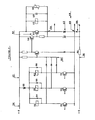
- the static trip device 10 is controlled by four current sensors, in particular current transformers 12, 14, 16, 18 in the form of toroids, magnetically coupled to the conductors R, S, T and N of a network.
- three-phase with neutral protected by a circuit breaker 20 with trip coil 22.
- Each secondary winding of the current transformers 12 to 16, associated with the conductors of phases R, S, T supplies a rectifier bridge 24, 26, 28 with diodes and a primary winding 23, 25, 27 of an earth transformer 30 with a ferromagnetic core playing the role of differential current detector.
- the secondary winding of the current transformer 18 associated with the neutral conductor N is connected directly to the primary winding 29 of the earth transformer 30.
- the secondary winding 31 of the latter performs the summation of the currents flowing in the network and delivers a signal to a full-wave rectifier bridge 32 when a differential fault occurs on the network.
- the outputs of the three rectifier bridges 24, 26, 28 are connected in series to cause a full-wave rectified voltage E to appear at the output terminals 34, 36.
- One of the outputs of the rectifier bridge 32, associated with the differential transformer 30, is connected to terminal 34 brought to the positive polarity of voltage E.
- the other output of bridge 32 is connected via a zero sequence resistor 39 to a terminal 38 of the negative polarity of voltage E.
- the device is of the own current type in which the current transformers 12 to 18 supply the signals for measuring the overload and zero sequence currents, and the supply of the electronic circuits of the static trip device 10, and of the coil 22 of trip of the circuit breaker 20.
- a measuring resistor 40 of the overload current connected between the terminals 36, 38 is the seat of a voltage signal proportional to the maximum value of the current flowing through the conductors R, S, T of the network.
- the résls- - Measuring tance 40 or any other means of detecting the presence of an overload current has an ohmic resistance of predetermined value or modified depending of the rated current of the circuit breaker.
- a series circuit, designated by the general reference 42, is connected to the output terminals 34 and 36 of the rectifier bridges 24, 26, 28 and comprises, in addition to the measurement resistor 40, a device 44 for supplying regulated DC voltage to the electronic circuits of the static trip device 10, and the circuit breaker 22 release circuit 20.
- the measurement resistor 40, the power supply 44 and the coil 22 are thus electrically connected in series in the circuit 42 supplied by the rectified voltage E.
- the voltage signal developed across the measurement resistor 40 is applied to a processing device 46 formed by a conventional peak detector circuit which it is unnecessary to describe in detail.
- the signal formed by the device 46 controls a long delay trigger circuit LR, a short delay trigger circuit CR, or any other trigger 48, which delivers a trigger signal when the current detected by the current transformers 12, 14, 16 exceeds a predetermined threshold or function.
- the trigger circuits CR 'and LR comprise, in a well known manner, operational amplifiers mounted in comparators and polarized at staggered thresholds so as to issue delayed trigger orders as a function of the level of the signal detected by the resistor 40, causing either a instantaneous short-circuit trip, i.e. a trip delayed by a duration depending on the overload value.
- the threshold amplifiers of the LR circuit cooperate with a timing device to define an amplitude and delay time function by ensuring a tripping curve in long delay steps in 1 2 t.
- the signal developed at the terminals of the zero sequence resistance 39 is applied to a zero sequence trip circuit H which provides a trip order when a differential fault detected by the transformer 30 occurs.
- the outputs of the long delay LR, short delay CR, zero sequence H and 48 trip circuits are connected to an OR gate 50 for controlling a static switching device 52 connected in parallel to the terminals of the circuit breaker trip coil 22.
- the bistable switch 52 is formed by two transistors 54, 56, the coil 22 being connected between the collector and the emitter of transistor 56, the base of which is connected to the collector of the first transistor 54.
- the transistor switch 52 54, 56 can be replaced by any other switching element with two operating states capable of finding themselves respectively in an unlocking state for shunting the coil 22 when a predetermined tripping threshold is not exceeded, and in a blocking state for the supply of the coil 22 during the delivery of a trip signal emitted by one of the trip circuits LR, CR, H or 48 after detection of an overload or differential current by one of the current transformers 24 to 30.
- a suppressor capacitor 58 and a voltage limiting element 60 of the Varistor type with non-linear resistance are connected respectively in parallel to the trip coil 22.
- the voltage developed across the terminals of the coil 22 in the blocked state of the switch 52 is thus limited when an overcurrent appears in the series circuit 42.
- the DC voltage supply device 44 for the electronic tripping circuits comprises a Zener diode 62, the cathode of which is connected to the connection point 64 of the emitter of the transistor 56, and of one of the terminals of the coil 22.
- L the anode of the Zener diode 62 is connected to the anode of a diode 66 connected by its cathode to the terminal 38 of the series circuit 42.
- the voltage taken at the intermediate point 68 of the connection of the anodes of the diodes 6 2, 66 serves of reference voltage and the positive and negative polarities of the DC supply voltage supplied by the device 44 are located respectively to the cathodes of the same diodes 62, 66.
- the outputs of the long delay LR, short delay CR and homopolar H trip circuits are respectively connected to the bases of three control transistors 70, 72, 74 whose collectors are connected on the one hand to the inputs of the logic circuit OR 50, and on the other hand to trip indicators 76, 78, 80 capable of determining the nature of the trip order during the conduction of one of the transistors 70 to 74, each emitter of which is at the reference potential of point 68.
- a diode Zener 82 connected between terminal 34 and the trip indicators 76, 78, 80 provides control of the signals when the voltage is sufficient at the terminals of the trip coil 22.
- Each trigger indicator 76 to 80 is shunted by a diode 84, 86, 88, the cathode of which is connected to the anode of the Zener diode 82.
- an auxiliary control device 90 causes initial release of the transistor switch 52 54, 56 to ensure the short-circuiting of the tripping coil 22 as soon as a current in the transformers of intensity 12 to 18.
- the zero sequence voltage signal from the resistor 39 is applied to the trip circuit H, which issues a differential trip order to the OR gate 50. It is the same for an overload or short-circuit current which causes the issuance of a delayed or instantaneous tripping order by one of the long delay LR or short delay CR trigger circuits controlled by the voltage across the terminals of the measurement resistance 40. Any one of these tripping orders ensures the blocking of the transistor 56 of the switch 52 resulting in the immediate excitation of the tripping coil 22 followed by the opening of the contacts of the circuit breaker 20. The nature of the fault is signaled simultaneously by the one of the tripping indicators 76, 78, 80.
- the measurement voltage across the resistors 39 and 40 and the supply 44 of the electronic tripping and monitoring circuits are maintained during the tripping phase preceding the opening of the circuit breaker.
- the impedance Z of the series circuit 42 increases, causing the rectified voltage E to increase and the majority of the electrical energy supplied by the rectifier bridges of the current generator then serves to power the coil. 22 trigger.
Landscapes
- Emergency Protection Circuit Devices (AREA)
- Driving Mechanisms And Operating Circuits Of Arc-Extinguishing High-Tension Switches (AREA)
Applications Claiming Priority (2)
| Application Number | Priority Date | Filing Date | Title |
|---|---|---|---|
| FR8007284A FR2479556A1 (fr) | 1980-03-31 | 1980-03-31 | Declencheur statique perfectionne pour disjoncteur electrique |
| FR8007284 | 1980-03-31 |
Publications (2)
| Publication Number | Publication Date |
|---|---|
| EP0037751A1 true EP0037751A1 (de) | 1981-10-14 |
| EP0037751B1 EP0037751B1 (de) | 1984-06-13 |
Family
ID=9240386
Family Applications (1)
| Application Number | Title | Priority Date | Filing Date |
|---|---|---|---|
| EP81400338A Expired EP0037751B1 (de) | 1980-03-31 | 1981-03-04 | Statischer Auslöser für einen elektrischen Schutzschalter |
Country Status (8)
| Country | Link |
|---|---|
| US (1) | US4380785A (de) |
| EP (1) | EP0037751B1 (de) |
| JP (1) | JPS56153919A (de) |
| CA (1) | CA1151279A (de) |
| DE (1) | DE3164057D1 (de) |
| ES (1) | ES500482A0 (de) |
| FR (1) | FR2479556A1 (de) |
| IN (1) | IN154155B (de) |
Cited By (3)
| Publication number | Priority date | Publication date | Assignee | Title |
|---|---|---|---|---|
| FR2612348A1 (fr) * | 1987-03-09 | 1988-09-16 | Merlin Gerin | Declencheur statique comportant un circuit de detection d'un courant homopolaire |
| NL1007122C2 (nl) * | 1997-09-25 | 1999-03-26 | Odink & Koenderink Bv | Schakelinrichting voor het beheren van een meerfasig wisselspanningsnet met een aantal gebruikseenheden. |
| EP1403994A1 (de) * | 2002-09-27 | 2004-03-31 | Siemens Aktiengesellschaft | Niederspannungs-Leistungsschalter mit zusätzlicher Schnellauslösung |
Families Citing this family (28)
| Publication number | Priority date | Publication date | Assignee | Title |
|---|---|---|---|---|
| US4642724A (en) * | 1982-06-22 | 1987-02-10 | S&C Electric Company | Trip signal generator for a circuit interrupter |
| JPS59189426U (ja) * | 1983-05-31 | 1984-12-15 | 松下電工株式会社 | 過電流保護装置 |
| US4571658A (en) * | 1983-06-22 | 1986-02-18 | S&C Electric Company | Control circuit for a circuit interrupter |
| US4567540A (en) * | 1983-06-22 | 1986-01-28 | S&C Electric Company | Power supply for a circuit interrupter |
| JPS60226718A (ja) * | 1984-04-24 | 1985-11-12 | 松下電工株式会社 | 引外し回路 |
| US4712151A (en) * | 1985-04-05 | 1987-12-08 | Square D Company | System for detection of ground faults in circuit breakers |
| EP0311649B1 (de) * | 1987-01-30 | 1993-11-18 | Square D Company | Zusatzmodul zur erdschlussermittlung |
| US4897756A (en) * | 1987-01-30 | 1990-01-30 | Square D Company | Add-on ground fault module |
| FR2612347B1 (fr) * | 1987-03-09 | 1989-05-26 | Merlin Gerin | Declencheur statique comportant un circuit de detection d'un courant homopolaire |
| JPH0620340B2 (ja) * | 1987-05-22 | 1994-03-16 | 寺崎電気産業株式会社 | 遮断器用過電流引外し装置 |
| JPH0340713A (ja) * | 1989-07-07 | 1991-02-21 | Fuji Electric Co Ltd | 過電流引き外し装置用電源回路 |
| US5136458A (en) * | 1989-08-31 | 1992-08-04 | Square D Company | Microcomputer based electronic trip system for circuit breakers |
| US5195009A (en) * | 1991-08-27 | 1993-03-16 | Siemens Energy & Automation, Inc. | Current summing arrangement for ground fault detection |
| US5224006A (en) * | 1991-09-26 | 1993-06-29 | Westinghouse Electric Corp. | Electronic circuit breaker with protection against sputtering arc faults and ground faults |
| ES2056744B1 (es) * | 1993-03-09 | 1997-12-16 | Ormazabal & Cie | Sistema integrado para proteccion de sobrecorriente y falta, de funcionamiento autonomo. |
| GB2276991A (en) * | 1993-03-22 | 1994-10-12 | B & R Electrical Plc | Protection circuit responsive to several sensors |
| ES2063693B1 (es) * | 1993-04-12 | 1998-01-01 | Gibert Enrique Guillen | Interruptor trifasico de control de potencia para corriente alterna en baja tension y cualquier tipo de desequilibrio de cargas entre fases. |
| US5539614A (en) * | 1993-09-29 | 1996-07-23 | Mitsubishi Denki Kabushiki Kaisha | Control unit, plug-in unit, transformer, zero-phase current transformer, and frequency measuring circuit applied to control center |
| DE4337344B4 (de) * | 1993-11-02 | 2005-08-25 | Moeller Gmbh | Strombegrenzendes Kontaktsystem für Leistungsschalter |
| US5969921A (en) * | 1998-01-29 | 1999-10-19 | Eaton Corporation | Ground fault electrical switching apparatus for coordinating tripping with a downstream ground fault switch |
| DE10214234A1 (de) * | 2002-03-26 | 2003-10-23 | Siemens Ag | Auf Kurzschluss ansprechende analogelektronische Auslöseeinrichtung für einen elektrischen Leistungsschalter |
| DE10343339B4 (de) * | 2003-09-12 | 2006-04-13 | Siemens Ag | Schaltungsanordnung zur Schnellausschaltung von Niederspannungs-Leistungsschaltern |
| US20080043393A1 (en) * | 2006-08-18 | 2008-02-21 | Honeywell International Inc. | Power switching device |
| JP4805396B2 (ja) * | 2010-03-31 | 2011-11-02 | ファナック株式会社 | モータ駆動装置 |
| CN105144526B (zh) * | 2012-12-04 | 2018-03-30 | Abb研究有限公司 | 具有提升性能的模块的自供保护继电器 |
| DE102015214966A1 (de) * | 2015-08-05 | 2017-02-09 | Ellenberger & Poensgen Gmbh | Schutzschalter |
| WO2017075677A1 (pt) * | 2015-11-06 | 2017-05-11 | Weg Drives & Controls - Automação Ltda. | Disjuntor com módulo de disparo plugável |
| CN114078654B (zh) * | 2020-08-11 | 2024-07-30 | 南京南瑞继保电气有限公司 | 一种环形电容器的固封极柱 |
Citations (4)
| Publication number | Priority date | Publication date | Assignee | Title |
|---|---|---|---|---|
| CH462937A (fr) * | 1965-04-23 | 1968-09-30 | Reyrolle A & Co Ltd | Circuit électrique sensible à une grandeur électrique |
| FR2212666A1 (de) * | 1973-01-02 | 1974-07-26 | Gen Electric | |
| US4004201A (en) * | 1975-08-25 | 1977-01-18 | General Electric Company | Multi-function solid state trip unit with trip indicating means |
| US4153924A (en) * | 1977-10-12 | 1979-05-08 | Mcgraw-Edison Company | Inrush current restraint circuit for alternating power system switch |
Family Cites Families (6)
| Publication number | Priority date | Publication date | Assignee | Title |
|---|---|---|---|---|
| US3786311A (en) * | 1973-01-02 | 1974-01-15 | Gen Electric | Circuit breaker and static trip circuit therefor |
| US3818275A (en) * | 1973-01-30 | 1974-06-18 | Westinghouse Electric Corp | Circuit interrupter including improved trip circuit using current transformers |
| US4060844A (en) * | 1976-02-17 | 1977-11-29 | I-T-E Imperial Corporation | Solid state tripping circuit |
| US4038695A (en) * | 1976-04-19 | 1977-07-26 | General Electric Company | Static trip unit for circuit protective devices |
| US4104691A (en) * | 1976-09-30 | 1978-08-01 | Westinghouse Electric Corp. | Circuit breaker apparatus including asymmetrical fault detector |
| US4068283A (en) * | 1976-10-01 | 1978-01-10 | General Electric Company | Circuit breaker solid state trip unit incorporating trip indicating circuit |
-
1980
- 1980-03-31 FR FR8007284A patent/FR2479556A1/fr active Granted
-
1981
- 1981-03-04 DE DE8181400338T patent/DE3164057D1/de not_active Expired
- 1981-03-04 EP EP81400338A patent/EP0037751B1/de not_active Expired
- 1981-03-17 US US06/244,691 patent/US4380785A/en not_active Expired - Lifetime
- 1981-03-18 ES ES500482A patent/ES500482A0/es active Granted
- 1981-03-30 CA CA000374229A patent/CA1151279A/en not_active Expired
- 1981-03-30 IN IN350/CAL/81A patent/IN154155B/en unknown
- 1981-03-31 JP JP4833681A patent/JPS56153919A/ja active Granted
Patent Citations (4)
| Publication number | Priority date | Publication date | Assignee | Title |
|---|---|---|---|---|
| CH462937A (fr) * | 1965-04-23 | 1968-09-30 | Reyrolle A & Co Ltd | Circuit électrique sensible à une grandeur électrique |
| FR2212666A1 (de) * | 1973-01-02 | 1974-07-26 | Gen Electric | |
| US4004201A (en) * | 1975-08-25 | 1977-01-18 | General Electric Company | Multi-function solid state trip unit with trip indicating means |
| US4153924A (en) * | 1977-10-12 | 1979-05-08 | Mcgraw-Edison Company | Inrush current restraint circuit for alternating power system switch |
Cited By (4)
| Publication number | Priority date | Publication date | Assignee | Title |
|---|---|---|---|---|
| FR2612348A1 (fr) * | 1987-03-09 | 1988-09-16 | Merlin Gerin | Declencheur statique comportant un circuit de detection d'un courant homopolaire |
| NL1007122C2 (nl) * | 1997-09-25 | 1999-03-26 | Odink & Koenderink Bv | Schakelinrichting voor het beheren van een meerfasig wisselspanningsnet met een aantal gebruikseenheden. |
| EP0905849A1 (de) * | 1997-09-25 | 1999-03-31 | Odink & Koenderink B.V. | Schalteinrichtung zur Verwaltung eines Mehrphasenwechselspannungnetzes mit einer Anzahl von Lasten |
| EP1403994A1 (de) * | 2002-09-27 | 2004-03-31 | Siemens Aktiengesellschaft | Niederspannungs-Leistungsschalter mit zusätzlicher Schnellauslösung |
Also Published As
| Publication number | Publication date |
|---|---|
| FR2479556A1 (fr) | 1981-10-02 |
| JPS56153919A (en) | 1981-11-28 |
| IN154155B (de) | 1984-09-29 |
| FR2479556B1 (de) | 1982-09-03 |
| ES8202452A1 (es) | 1982-02-01 |
| EP0037751B1 (de) | 1984-06-13 |
| JPH0152974B2 (de) | 1989-11-10 |
| US4380785A (en) | 1983-04-19 |
| DE3164057D1 (en) | 1984-07-19 |
| CA1151279A (en) | 1983-08-02 |
| ES500482A0 (es) | 1982-02-01 |
Similar Documents
| Publication | Publication Date | Title |
|---|---|---|
| EP0037751B1 (de) | Statischer Auslöser für einen elektrischen Schutzschalter | |
| US4347541A (en) | Circuit breaker | |
| EP0258091B1 (de) | Selbstüberwachte, statische, numerische Auslöseeinrichtung | |
| EP0235479B1 (de) | Statischer Auslöser mit Testschaltung für elektrischen Leistungsschalter | |
| US4034360A (en) | System for disabling the reset circuit of fault indicating means | |
| EP0326459B1 (de) | Statischer Auslöseschalter mit einer Schaltung mit Sofort-Auslösung, unabhängig von der Versorgungsspannung | |
| EP0244284B1 (de) | Statischer Momentanauslöser für einen begrenzenden Leistungsschalter | |
| US4425596A (en) | Electric circuit breaker | |
| US8810986B2 (en) | Circuit breaker | |
| US3974446A (en) | Polyphase fault current flow detecting and resetting means | |
| FR2651915A1 (fr) | Disjoncteur statique ultra-rapide a isolement galvanique. | |
| JPH05501043A (ja) | 中性点もしくは接地喪失保護回路 | |
| US7161775B2 (en) | Arc fault circuit breaker and apparatus for detecting wet track arc fault | |
| CA2414826C (en) | Arc fault detector immune to dimmer transients and a circuit breaker incorporating the same | |
| US3887849A (en) | Protective circuit | |
| EP0605335B1 (de) | Elektronischer Auslöser mit Testgerät | |
| HU220493B1 (hu) | Hibaáram-védőkapcsoló | |
| US3609459A (en) | Variable voltage compensated load measuring circuits for controlled closure of single-pole devices | |
| JP3137029B2 (ja) | 系統連系装置における素子故障検出装置 | |
| EP0129454A1 (de) | Messverfahren um die Verfügbarkeit einer getakteten elektrischen Stromversorgung festzustellen und Vorrichtung zu seiner Durchführung | |
| EP0105786B1 (de) | Abzweigschalter mit einem elektronischen Auslöser und einer ferngesteuerten Einstellung | |
| FR2500210A1 (fr) | Alimentation electrique secteur de securite perfectionnee a relais | |
| CN210724190U (zh) | 一种具有抗电源干扰功能的漏电断路器 | |
| CA1063226A (en) | Multi-function solid state trip unit with trip indicating means | |
| SU213710A1 (ru) | Устройство избирательной защиты линии электропередачи постоянного тока |
Legal Events
| Date | Code | Title | Description |
|---|---|---|---|
| PUAI | Public reference made under article 153(3) epc to a published international application that has entered the european phase |
Free format text: ORIGINAL CODE: 0009012 |
|
| AK | Designated contracting states |
Designated state(s): BE CH DE GB IT NL SE |
|
| 17P | Request for examination filed |
Effective date: 19820308 |
|
| ITF | It: translation for a ep patent filed | ||
| GRAA | (expected) grant |
Free format text: ORIGINAL CODE: 0009210 |
|
| AK | Designated contracting states |
Designated state(s): BE CH DE GB IT LI NL SE |
|
| REF | Corresponds to: |
Ref document number: 3164057 Country of ref document: DE Date of ref document: 19840719 |
|
| PLBI | Opposition filed |
Free format text: ORIGINAL CODE: 0009260 |
|
| 26 | Opposition filed |
Opponent name: AEG-TELEFUNKEN AKTIENGESELLSCHAFT, BERLIN UND FRAN Effective date: 19850311 |
|
| NLR1 | Nl: opposition has been filed with the epo |
Opponent name: AEG-TELEFUNKEN AG. |
|
| PLBN | Opposition rejected |
Free format text: ORIGINAL CODE: 0009273 |
|
| STAA | Information on the status of an ep patent application or granted ep patent |
Free format text: STATUS: OPPOSITION REJECTED |
|
| 27O | Opposition rejected |
Effective date: 19860329 |
|
| NLR2 | Nl: decision of opposition | ||
| PGFP | Annual fee paid to national office [announced via postgrant information from national office to epo] |
Ref country code: CH Payment date: 19900322 Year of fee payment: 10 |
|
| PGFP | Annual fee paid to national office [announced via postgrant information from national office to epo] |
Ref country code: NL Payment date: 19900331 Year of fee payment: 10 |
|
| ITTA | It: last paid annual fee | ||
| PG25 | Lapsed in a contracting state [announced via postgrant information from national office to epo] |
Ref country code: LI Effective date: 19910331 Ref country code: CH Effective date: 19910331 |
|
| PG25 | Lapsed in a contracting state [announced via postgrant information from national office to epo] |
Ref country code: NL Effective date: 19911001 |
|
| NLV4 | Nl: lapsed or anulled due to non-payment of the annual fee | ||
| REG | Reference to a national code |
Ref country code: CH Ref legal event code: PL |
|
| PGFP | Annual fee paid to national office [announced via postgrant information from national office to epo] |
Ref country code: SE Payment date: 19930315 Year of fee payment: 13 |
|
| PGFP | Annual fee paid to national office [announced via postgrant information from national office to epo] |
Ref country code: BE Payment date: 19930409 Year of fee payment: 13 |
|
| PGFP | Annual fee paid to national office [announced via postgrant information from national office to epo] |
Ref country code: GB Payment date: 19940222 Year of fee payment: 14 |
|
| PG25 | Lapsed in a contracting state [announced via postgrant information from national office to epo] |
Ref country code: SE Free format text: LAPSE BECAUSE OF NON-PAYMENT OF DUE FEES Effective date: 19940305 |
|
| PG25 | Lapsed in a contracting state [announced via postgrant information from national office to epo] |
Ref country code: BE Effective date: 19940331 |
|
| BERE | Be: lapsed |
Owner name: MERLIN GERIN Effective date: 19940331 |
|
| EUG | Se: european patent has lapsed |
Ref document number: 81400338.0 Effective date: 19941010 |
|
| PG25 | Lapsed in a contracting state [announced via postgrant information from national office to epo] |
Ref country code: GB Effective date: 19950304 |
|
| GBPC | Gb: european patent ceased through non-payment of renewal fee |
Effective date: 19950304 |
|
| PGFP | Annual fee paid to national office [announced via postgrant information from national office to epo] |
Ref country code: DE Payment date: 19970214 Year of fee payment: 17 |
|
| PG25 | Lapsed in a contracting state [announced via postgrant information from national office to epo] |
Ref country code: DE Free format text: LAPSE BECAUSE OF NON-PAYMENT OF DUE FEES Effective date: 19981201 |