EP0037791A2 - Jagdgewehr - Google Patents
Jagdgewehr Download PDFInfo
- Publication number
- EP0037791A2 EP0037791A2 EP81420049A EP81420049A EP0037791A2 EP 0037791 A2 EP0037791 A2 EP 0037791A2 EP 81420049 A EP81420049 A EP 81420049A EP 81420049 A EP81420049 A EP 81420049A EP 0037791 A2 EP0037791 A2 EP 0037791A2
- Authority
- EP
- European Patent Office
- Prior art keywords
- barrel
- lever
- finger
- breech
- trigger
- Prior art date
- Legal status (The legal status is an assumption and is not a legal conclusion. Google has not performed a legal analysis and makes no representation as to the accuracy of the status listed.)
- Granted
Links
Images


Classifications
-
- F—MECHANICAL ENGINEERING; LIGHTING; HEATING; WEAPONS; BLASTING
- F41—WEAPONS
- F41C—SMALLARMS, e.g. PISTOLS, RIFLES; ACCESSORIES THEREFOR
- F41C7/00—Shoulder-fired smallarms, e.g. rifles, carbines, shotguns
-
- F—MECHANICAL ENGINEERING; LIGHTING; HEATING; WEAPONS; BLASTING
- F41—WEAPONS
- F41A—FUNCTIONAL FEATURES OR DETAILS COMMON TO BOTH SMALLARMS AND ORDNANCE, e.g. CANNONS; MOUNTINGS FOR SMALLARMS OR ORDNANCE
- F41A19/00—Firing or trigger mechanisms; Cocking mechanisms
- F41A19/06—Mechanical firing mechanisms, e.g. counterrecoil firing, recoil actuated firing mechanisms
- F41A19/25—Mechanical firing mechanisms, e.g. counterrecoil firing, recoil actuated firing mechanisms having only slidably-mounted striker elements, i.e. percussion or firing pins
- F41A19/27—Mechanical firing mechanisms, e.g. counterrecoil firing, recoil actuated firing mechanisms having only slidably-mounted striker elements, i.e. percussion or firing pins the percussion or firing pin being movable relative to the breech-block
- F41A19/29—Mechanical firing mechanisms, e.g. counterrecoil firing, recoil actuated firing mechanisms having only slidably-mounted striker elements, i.e. percussion or firing pins the percussion or firing pin being movable relative to the breech-block propelled by a spring under tension
- F41A19/30—Mechanical firing mechanisms, e.g. counterrecoil firing, recoil actuated firing mechanisms having only slidably-mounted striker elements, i.e. percussion or firing pins the percussion or firing pin being movable relative to the breech-block propelled by a spring under tension in bolt-action guns
Definitions
- the invention relates to a repeating hunting rifle with safety devices and a firing and cocking mechanism arranged in front of the magazine.
- repeating rifles corresponding to the preamble of claim 1, comprising an arming mechanism disposed at the front of the magazine and at the front end of the movable breech, to be controlled by a transmission device housed in the bole forming butt and ending in the trigger mechanism.
- Such rifles are of a complicated construction and operation and do not comprise multiple safety devices acting on the one hand, either automatically when the cocking lever is closed and the movable bolt locked, in view to prevent firing in the event of incomplete closure, either by means of a manual command for blocking said breech in the closed and locked position, as well as on the armed striker, and also on the trigger mechanism.
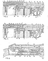
- this rifle essentially comprises a barrel tube (1) the rear end of which is made integral by fitting, pin or other means, of the end of the cylinder head box (2), while an intermediate squared element (3) enables the stock (4) to be fixed.
- the stock (4) arranged along the entire length of the weapon forms a hollow rectilinear upper face, of semicircular section (4 1 ) at the front, to allow the support and the housing of the half-section of the tube (1), while its part rear partially covers the upper part of the box (2), while forming a lateral clearance (4 2 ) and a longitudinal opening (4 3 ) intended for the movement and pivoting of the cocking and locking lever (5).
- This stick (4) is fixed by screws (6) arranged vertically in a corresponding housing (4 4 ), to be screwed into a hole of the square element (3) and also by a second screw (7) cooperating with a hole tapped located at the rear of the cylinder head box (2).
- a plate (8) fixed to the lower rear part of the stick (4) has an oblong opening for the housing and the removable fixing of a magazine (9) of any known type, intended to convey the bales through a lower aperture corresponding eure r i (2 1) established in the rear end of the receiver (2).
- the butt (4) also forms at the front of the magazine (9) and substantially at its middle part, an axial mortise (4 5 ) allowing the embedding and fixing of the trigger guard (10) by means of screws (11 ) cooperating with retaining plates (12) housed in corresponding recesses.
- the movable cylinder head (13) forms a clearance constituting a helical ramp (13) on which a roller (14) mounted in the yoke portion of the rear head (15 1 ) of the striker (15), provided also of two prominent transverse sectors (15 2 ) also cooperating at the end of the cylinder head closing stroke, with the grooves of the box (2).
- the striker (15 3 ) proper, thus controlled, is returned towards the front, by the detent action of a coil spring (16) interposed between a fixed ring (17) integral with the box (2), and a support ring (18), while its front end forms a cylindrical head with a longitudinal recess ( 15 4 ) in which is housed in thickness, a rocker trigger (19) returned by spring (20).
- the trigger (19) forms a beak (19 1 ) at its front end, for hooking when cocking the striker, with a shoulder corresponding to the bore of the movable bolt (13) disposed near its end. Said striker (15 3 ) crosses, during firing, the front part of the movable breech (13).
- the trigger (19) is in the cocking position, opposite a movable finger or ball (21) housed in the thickness of the movable yoke (13).
- This finger (21) is in the closure and locking of the bolt (13) in positive ion t firing in contact with the end of a lift lever (22) vertically disposed to slide in a support (23) integral with the square element (3), by means of the screw (6), while a coil spring (24) ensures the return of said lever (22) in the low position.
- a bracket (25) pivots around the axis (26) integral with the support (23), to be biased by its vertical branch, by the end yoke (27 1 ) established at the end of a movable rod (27) sliding freely in a hole in the element (3) and at the front in a cleat (28) secured to the barrel tube (1).
- a ring (29) adjustable in position is fixed to the front of said rod (27) to allow the support of a return spring (30) and the spout (31) of the trigger (31) housed at articulation, around the axis (32), in the trigger guard (10) integral with the stock (4).
- the permanent support of the spout (31 1) of the trigger (31) on the ring (29) is ensured by means of a pin spring (33) housed around an axis in a recess of the trigger guard (10).
- the trigger (31) is furthermore established in its thickness with a slot allowing the engagement of a lever (34) articulated freely around an axis (35) passing through the thickness of said trigger (31) at its upper part. .
- This lever (34) forms at the front spout (34 1 ) to rest on the end of a leaf spring (36) fixed in a recess in the trigger guard (10).
- This arrangement makes it possible, when the manual pressure is exerted on the lever (34), to first obtain a click caused by the sudden release of the spout (34 1 ) relative to the end of the leaf spring ( 36), and secondly the controlled support on the trigger (31) proper.
- the latter acts by its beak (31 1 ) on the ring (29), for the longitudinal displacement towards the front of the rod (27) which controls the trigger (20) via the finger (21), of the lifting lever (22) and of the pivoting bracket (25), so as to cause the firing.
- this expansion device (31) placed at the front of the charger can control in the same way, by the rod (27), any other starting device of a movable cylinder head, placed either at the front of the charger, ie at the rear
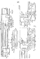
- FIG. 6 a known rifle, comprising an incorporated magazine (37) with rotary conveyor with cartridge housings (38).
- the rod (27) slides freely in an axial opening (37 1 ) of said magazine (37), to form a cam (27 2 ) at its rear end, so as to control the pivoting of the cocking trigger ( 39), with a view to firing by the sudden displacement of the striker rod (40) housed in the cylinder head (41).
- the lifting lever / returned by the spring (47) is in permanent contact with the end of an arm (48) provided with an adjusting screw (49 ) and housed in a slot in the support (45).
- This arm (48) articulated on the axis (50) passing through the support (45), is biased at the front via the end of the movable rod (51), by means of a link (52 ) pivoting around the axis (53).
- the movable rod (51) is coupled at the front with the trigger, not shown, as indicated above, so as to control the upward movement of the lifting lever (44), for firing.
- the arm (48) is further provided transversely with an overhanging finger (54) which moves vertically by means of a clearance (45 1 ) of the support (45), and forms a stop in relation to the lower ends of the squared levers ( 55 and 56) mounted laterally superimposed on said support (45).
- the lower lever (55) slides by its horizontal light (55 1 ) crossed by a lug (57) integral with the support (45), so as to present its lower face (55 2 ) overlapping or not with respect to the finger ( 54), thereby forming a retractable stop, while its upper part forms a vertical rear leg (55 3 ), which is coupled to a horizontal rod (58) controlled in translation by the manual control mechanism of the safety device.
- the cylinder head (42) and the striker (43) as indicated below.
- the external lever (56) pivots about the axis (59) to present or not its lower face (56 1 ) overlapping on the finger (54), while its upper vertical branch (56 2 ) is arranged transversely opposite and in slight rear longitudinal overflow with respect to the notch (46 ') of the cylinder head box (46) intended for the circular interlocking of the cocking and locking lever (42 1 ) of the movable cylinder head (42).
- the lever (42 1 ) presses, by its section corresponding to the notch (46 1 ), on the rounded end ( 56 3 ) of the branch (56 2 ) to cause it to pivot about of the axis (59), along arrow F, so as to release the finger (54) in height.
- the arm (48) can thus act on the lifting lever (44), for the purpose of firing caused by the manual action exerted on the trigger. It should be noted, however, that the firing can only be carried out in combination with the erasure of the underside (552) of the lever (55), caused by the release of the safety device with manual control of the breech (42) and the striker (43).
- the device for securing the cylinder head (42) in the closed position and the striker (43) in the armed position, also acting by the horizontal rod (58), on the lower lever (55), is arranged at the rear of the rifle.
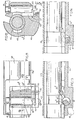
- the cylinder head box (46) externally forms a transverse boss (462) pierced vertically for the free-rotation mounting of a barrel (60) provided at its upper part with an operating lever (61), for manual training.
- This barrel (60) is also presented transversely, when cocking, opposite the front shoulder formed by one of the prominent rear sectors (43 1 ) of the striker (43) intended for its longitudinal guidance in the box. (46). To this end, the barrel (60) forms a profiled section with a heel (60 1 ) which acts in abutment, in the safety position, against the sector or shoulder (43 1 ) of the striker (43) armed, so as to lock longitudinally.
- an adjacent recessed face (60 2 ) allows during rotation of the barrel (60), in view of the dega safety, erasing the heel (60 1 ) for the free passage of the sector (43), when fired, as illustrated in Figure 14.
- the lower end of the barrel (60) forms a facial cam (60 3 ) on which the end of the horizontal lower arm (62 1 ) of a latch (62) bears, the vertical rod (62 2 ) of which slides in the 'thickness of the box (46) and engages at the end in the safety position, in a corresponding notch (42 2 ) of the movable yoke (42), when it is closed and locked; a spring (63) acting on the latch (62), ensures permanent contact of its arm (62 1 ) on the facial cam (60 3 ).
- the end of the barrel (60) receives in overflow an eccentric finger (64) which, by means of a link (65), controls the longitudinal displacement in translation of the horizontal rod (58) integral of the lower lever (55).
- the safety of the striker (43) in the armed position and that of the bolt (42) in the closed position is ensured simultaneously by a horizontal barrel (63) mounted in a transverse boss of the cylinder head box (46) and driven in rotation by its peripheral toothing which meshes with an upper wheel (64) provided with a control finger (64 1 ).
- This barrel (63) is established over its entire length with a sector-shaped clearance (63 1 ), which authorizes the out-of-safety position for the free passage of the sector (43) of the striker (43) during firing, as well as front sectors (42 3 ) of the cylinder head (42), when it is released from the cylinder head box (46).
- the barrel (63) forms a radial beak (63 2 ) disposed at the front end and intended to engage during the rotation of said barrel in the safety position, in a cavity ( 42 4 ) of the bolt (42) previously armed and locked, in the notch: (46 1 ) by the lever ( 42 1 ) .
- the upper part of the clearance (63 1 ) constitutes a heel (63 4 ) the transverse front face of which forms a stop for the movable yoke (42) relative to the rear end of one of the sectors (42 3 ), preventing its disengagement towards the rear of the cylinder head box (46) for its disassembly.
- the barrel (63) also comprises on its outer periphery, a finger (65) which cooperates in abutment on the sloping face (66 1 ) forming a ramp, of a pivoting lever (66) articulated around an axis (67) and coupled to its base at the end of the horizontal rod (58) acting on the lever (55), as indicated above.
Landscapes
- Engineering & Computer Science (AREA)
- General Engineering & Computer Science (AREA)
- Aiming, Guidance, Guns With A Light Source, Armor, Camouflage, And Targets (AREA)
Priority Applications (1)
| Application Number | Priority Date | Filing Date | Title |
|---|---|---|---|
| AT81420049T ATE8934T1 (de) | 1980-04-04 | 1981-04-02 | Jagdgewehr. |
Applications Claiming Priority (4)
| Application Number | Priority Date | Filing Date | Title |
|---|---|---|---|
| FR8008102 | 1980-04-04 | ||
| FR8008102A FR2479965A1 (fr) | 1980-04-04 | 1980-04-04 | Carabine de chasse a repetition avec mecanisme de tir et d'armement dispose a l'avant du chargeur |
| FR8106352A FR2502321A2 (fr) | 1981-03-23 | 1981-03-23 | Carabine de chasse a repetition avec mecanisme de tir et d'armement dispose a l'avant du chargeur |
| FR8106352 | 1981-03-23 |
Publications (3)
| Publication Number | Publication Date |
|---|---|
| EP0037791A2 true EP0037791A2 (de) | 1981-10-14 |
| EP0037791A3 EP0037791A3 (en) | 1982-01-27 |
| EP0037791B1 EP0037791B1 (de) | 1984-08-08 |
Family
ID=26221709
Family Applications (1)
| Application Number | Title | Priority Date | Filing Date |
|---|---|---|---|
| EP19810420049 Expired EP0037791B1 (de) | 1980-04-04 | 1981-04-02 | Jagdgewehr |
Country Status (2)
| Country | Link |
|---|---|
| EP (1) | EP0037791B1 (de) |
| DE (1) | DE3165339D1 (de) |
Cited By (2)
| Publication number | Priority date | Publication date | Assignee | Title |
|---|---|---|---|---|
| FR2592149A1 (fr) * | 1985-12-20 | 1987-06-26 | Gex Dumez Sa | Support de lunette de visee pour carabines et armes similaires. |
| WO1998038467A1 (en) * | 1997-02-25 | 1998-09-03 | Varbanov, Ivailo Youlianov | Trigger mechanism |
Family Cites Families (6)
| Publication number | Priority date | Publication date | Assignee | Title |
|---|---|---|---|---|
| DE162313C (de) * | ||||
| DE106939C (de) * | ||||
| GB110699A (en) * | 1917-04-12 | 1917-11-01 | George Waterworth Younger | Improvements in Small Arms. |
| DE1264294B (de) * | 1965-12-16 | 1968-03-21 | Juergen Roehrdanz | Verschluss fuer Handfeuerwaffen |
| US3611872A (en) * | 1969-06-02 | 1971-10-12 | Dale M Davis | Lightweight compact rifle |
| DE2630213A1 (de) * | 1976-07-05 | 1978-01-19 | Walter Gehmann | Repetiergewehr |
-
1981
- 1981-04-02 EP EP19810420049 patent/EP0037791B1/de not_active Expired
- 1981-04-02 DE DE8181420049T patent/DE3165339D1/de not_active Expired
Cited By (2)
| Publication number | Priority date | Publication date | Assignee | Title |
|---|---|---|---|---|
| FR2592149A1 (fr) * | 1985-12-20 | 1987-06-26 | Gex Dumez Sa | Support de lunette de visee pour carabines et armes similaires. |
| WO1998038467A1 (en) * | 1997-02-25 | 1998-09-03 | Varbanov, Ivailo Youlianov | Trigger mechanism |
Also Published As
| Publication number | Publication date |
|---|---|
| EP0037791A3 (en) | 1982-01-27 |
| EP0037791B1 (de) | 1984-08-08 |
| DE3165339D1 (en) | 1984-09-13 |
Similar Documents
| Publication | Publication Date | Title |
|---|---|---|
| BE1007244A3 (fr) | Mecanisme de detente pour armes a feu. | |
| FR2544849A1 (fr) | Dispositif de verrouillage des canons et de la sous-garde interchangeable, commande par la cle de fermeture, pour fusils de chasse | |
| EP0470012A1 (de) | Einschüssige Handfeuerwaffe | |
| EP1003007B1 (de) | Abzugsmechanismus für Feuerwaffen | |
| EP0095399B1 (de) | Von Doppelabzug auf Einzelabzug umstellbarer Abzugsmechanismus für Jagdgewehr | |
| EP0037791A2 (de) | Jagdgewehr | |
| EP0203034B1 (de) | Schusszahlbegrenzer für Serienfeuer an automatischen Waffen | |
| FR2502321A2 (fr) | Carabine de chasse a repetition avec mecanisme de tir et d'armement dispose a l'avant du chargeur | |
| EP0661514B1 (de) | Waffe mit bewegbaren Verschlussstücken | |
| FR2474156A3 (de) | ||
| FR2479965A1 (fr) | Carabine de chasse a repetition avec mecanisme de tir et d'armement dispose a l'avant du chargeur | |
| EP0687883B1 (de) | Abfeuerungsvorrichtung für Geschütz durch den Schlag eines Zünders und Geschütz mit einer solcher Vorrichtung | |
| FR3135319A3 (fr) | Dispositif de commutation coup unique/répétition pour arme à feu-jouet | |
| EP0260204B1 (de) | Gasdruckbetätigtes automatisches Gewehr, z.B. Kipplaufgewehr | |
| BE399933A (de) | ||
| FR2743874A1 (fr) | Dispositif d'armement d'une carabine superposee | |
| FR2572507A1 (fr) | Fusil automatique perfectionne a canon basculant ou non | |
| BE1001909A3 (fr) | Dispositif de detente pour armes automatiques. | |
| FR2572801A1 (fr) | Pistolet a barillet | |
| FR2528963A1 (fr) | Carabine a repetition avec ou sans chargeur | |
| BE527936A (de) | ||
| FR2765317A1 (fr) | Mecanisme d'armement desarmable pour fusil | |
| EP0399984A1 (de) | Hammersicherung für Feuerwaffen | |
| FR2586796A1 (fr) | Perfectionnements aux mecanismes des revolvers a simple et double action | |
| FR2639427A1 (fr) | Dispositif de gachette a armement et declenchement separes pour armes de chasse sous-marine |
Legal Events
| Date | Code | Title | Description |
|---|---|---|---|
| PUAI | Public reference made under article 153(3) epc to a published international application that has entered the european phase |
Free format text: ORIGINAL CODE: 0009012 |
|
| AK | Designated contracting states |
Designated state(s): AT BE CH DE GB IT LU NL SE |
|
| PUAL | Search report despatched |
Free format text: ORIGINAL CODE: 0009013 |
|
| AK | Designated contracting states |
Designated state(s): AT BE CH DE GB IT LU NL SE |
|
| 17P | Request for examination filed |
Effective date: 19820419 |
|
| GRAA | (expected) grant |
Free format text: ORIGINAL CODE: 0009210 |
|
| AK | Designated contracting states |
Designated state(s): AT BE CH DE GB IT LI LU NL SE |
|
| PG25 | Lapsed in a contracting state [announced via postgrant information from national office to epo] |
Ref country code: SE Effective date: 19840808 Ref country code: NL Effective date: 19840808 Ref country code: IT Free format text: LAPSE BECAUSE OF FAILURE TO SUBMIT A TRANSLATION OF THE DESCRIPTION OR TO PAY THE FEE WITHIN THE PRESCRIBED TIME-LIMIT;WARNING: LAPSES OF ITALIAN PATENTS WITH EFFECTIVE DATE BEFORE 2007 MAY HAVE OCCURRED AT ANY TIME BEFORE 2007. THE CORRECT EFFECTIVE DATE MAY BE DIFFERENT FROM THE ONE RECORDED. Effective date: 19840808 Ref country code: AT Effective date: 19840808 |
|
| REF | Corresponds to: |
Ref document number: 8934 Country of ref document: AT Date of ref document: 19840815 Kind code of ref document: T |
|
| REF | Corresponds to: |
Ref document number: 3165339 Country of ref document: DE Date of ref document: 19840913 |
|
| NLV1 | Nl: lapsed or annulled due to failure to fulfill the requirements of art. 29p and 29m of the patents act | ||
| PG25 | Lapsed in a contracting state [announced via postgrant information from national office to epo] |
Ref country code: LU Free format text: LAPSE BECAUSE OF NON-PAYMENT OF DUE FEES Effective date: 19850430 Ref country code: BE Effective date: 19850430 |
|
| PLBE | No opposition filed within time limit |
Free format text: ORIGINAL CODE: 0009261 |
|
| STAA | Information on the status of an ep patent application or granted ep patent |
Free format text: STATUS: NO OPPOSITION FILED WITHIN TIME LIMIT |
|
| 26N | No opposition filed | ||
| BERE | Be: lapsed |
Owner name: GEX-DUMEZ S.A. Effective date: 19850402 |
|
| GBPC | Gb: european patent ceased through non-payment of renewal fee | ||
| PG25 | Lapsed in a contracting state [announced via postgrant information from national office to epo] |
Ref country code: LI Effective date: 19860430 Ref country code: CH Effective date: 19860430 |
|
| REG | Reference to a national code |
Ref country code: CH Ref legal event code: PL |
|
| PG25 | Lapsed in a contracting state [announced via postgrant information from national office to epo] |
Ref country code: DE Effective date: 19870101 |
|
| PG25 | Lapsed in a contracting state [announced via postgrant information from national office to epo] |
Ref country code: GB Effective date: 19881118 |