EP0037806A2 - Ballmaschine mit grosser Schussgenauigkeit - Google Patents
Ballmaschine mit grosser Schussgenauigkeit Download PDFInfo
- Publication number
- EP0037806A2 EP0037806A2 EP81870018A EP81870018A EP0037806A2 EP 0037806 A2 EP0037806 A2 EP 0037806A2 EP 81870018 A EP81870018 A EP 81870018A EP 81870018 A EP81870018 A EP 81870018A EP 0037806 A2 EP0037806 A2 EP 0037806A2
- Authority
- EP
- European Patent Office
- Prior art keywords
- balloon
- axis
- ball
- impact
- trajectory
- Prior art date
- Legal status (The legal status is an assumption and is not a legal conclusion. Google has not performed a legal analysis and makes no representation as to the accuracy of the status listed.)
- Granted
Links
Images
Classifications
-
- A—HUMAN NECESSITIES
- A63—SPORTS; GAMES; AMUSEMENTS
- A63B—APPARATUS FOR PHYSICAL TRAINING, GYMNASTICS, SWIMMING, CLIMBING, OR FENCING; BALL GAMES; TRAINING EQUIPMENT
- A63B69/00—Training appliances or apparatus for special sports
- A63B69/40—Stationarily-arranged devices for projecting balls or other bodies
Definitions
- European patent 80200346.7 describes, through a few exemplary embodiments, a device in which the percussion lever is of low mass and which is arranged to recover, before impact with the ball, the kinetic energy accumulated by the other elements of motion transmission.
- a player modifies the point of impact on the ball so that it is animated by a rotational movement around an axis which depends on the position of the point d impact relative to the center of gravity of the ball.
- European patent 79200221.4 describes a device which gives a left trajectory to the balloon by imposing on the latter, in the sending position, a rotation of predetermined speed around a predetermined axis.
- the positioning cup which, by suction, firmly holds the ball before kick-off and / or the size of the drive device, possibly giving this positioning cup a rotational movement at a determined speed it may be that despite an adjustment in height of the positioning cup the percussive mass of the balloon launcher does not strike the balloon low enough to obtain the desired type of trajectory.
- the primary trajectory given to the ball by the impact of the striking mass must be modified by an appropriate device.
- the usual way is to arrange an inclined plane according to a chosen slope at a determined level.
- the contact between the balloon and the inclined plane communicates to the balloon a rotation about a horizontal axis perpendicular to the greatest slope of the inclined plane.
- This rotation modifies the trajectory of the ball by shortening its point of fall and gives a false rebound.
- the ball is felt more harshly.
- the modification of the coefficient of friction between the ball and the inclined plane depending on whether both are dry, wet, covered with mud ... the trajectory is not very repetitive during successive shots.
- the present invention overcomes the various drawbacks mentioned above thanks to the fact that the percussive end of the percussion lever is shaped to have several points of impact simultaneously striking the ball and arranged symmetrically with respect to a plane passing through the departure path of the ball.
- the symmetrical arrangement of the impact points of the percussive end with respect to the plane perpendicular to the axis of suspension of the lever passing through the balloon's departure trajectory compensates for the surface irregularities of the balloon and greatly reduces the deformation of the outer envelope thereof In this way, this device improves the precision of the trajectory of the balloon.
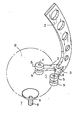
- Figure 1 shows an embodiment of a percussive mass 1 distributed at several points.
- a percussion lever 2 is terminated by a fork made up of two teeth 3 each equipped, at the free end, with an axis 4 intended to receive two rollers 5 free to rotate around this axis 4.
- the orientation of each axis 4 is approximately parallel to the axis of rotation along which the ball turns when wants to communicate a left path to it.
- Each axis 4 is therefore parallel to the axis of rotation 6 ′ of a presentation device 7 for the balloon 8 .
- the balloon 8 shown in phantom is placed on a small diameter cup 9 connected to a non-suction system shown which maintains the balloon 8 on the cup regardless of the speed of rotation of the presentation device 7.
- the orientation of the teeth 3 of the fork can be adjustable by an appropriate device for modifying the points of impact of the rollers 5 on the ball 8.
- the balloon 8 When the striking mass hits, by means of the four rollers 5, the balloon 8 simultaneously at four points, the deformation of the outer envelope of the balloon 8 is slight and practically does not interfere with the rotation given beforehand to the balloon 8 along the axis 6 In addition, the striking of the ball, distributed in several points, requires less of its envelope and thus contributes to reducing wear.
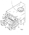
- FIG. 2 represents an exemplary embodiment of the device for modifying the trajectory of the balloons.
- a stirrup 10 made integral with the frame II by fixing means comprises two branches 12 arranged symmetrically with respect to the plane defined by the arrival and departure trajectories of the ball.
- This bracket 10 serves as a support for a movable assembly 13 which can oscillate around a horizontal axis 14, 'placed perpendicular to the plane defined by the first and modified trajectories of the balloon to occupy either a high position or a low position as shown in Figure 2.
- This movable assembly 13 comprises two forks 15 each threaded on a branch 12 of the stirrup 10 and joined together by a flat 16.
- Each fork 15 carries an axis 17, parallel to the axis 14, around which a roller 18 freely pivots These rollers 18 occupy a symmetrical position relative to the plane perpendicular to the axis 14 passing through the modified trajectory of the balloon.
- balloon 8 When balloon 8 is fired, it strikes the rollers 18 which, according to the adjustable position of the mobile assembly 13 deviates more or less strongly the first trajectory. of the balloon to give it a modified, more ascending trajectory.
- the rollers 18 are of small diameter and of low inertia.
- the position of the rollers 5 and 18 is symmetrical both to the plane of movement of the percussion arm 2 and to the shooting axis of the ball.
- the symmetry with respect to the plane of movement of the percussion arm 2 ensures, on the one hand, good centering of the balloon 8 when the rollers 5 release it from the positioning cup 9 and project it forward.
- the symmetry with respect to the firing axis allows, on the other hand, the rollers 18 to maintain the correct guidance of the balloon 8 when it crashes on these rollers and then reshapes resiliently to resume a more ascending trajectory.
- the rollers are cylindrical in shape with strongly rounded edges so as not to damage the balloons.
- the shape, the diameter or the number of rollers can vary as long as the principle of a symmetrical arrangement with respect to the plane of movement of the percussion arm is respected.
- the rollers 5 and 18 can be of frustoconical or hyperbolic shape.
- the invention is in no way limited to the examples of realization described by way of example.
- it includes all the technical equivalents executed according to its spirit and in particular percussive masses according to the invention which are not mounted on the end of a percussion lever, but for example on the end of a piston.
Landscapes
- Health & Medical Sciences (AREA)
- General Health & Medical Sciences (AREA)
- Physical Education & Sports Medicine (AREA)
- Toys (AREA)
- Pinball Game Machines (AREA)
- Finish Polishing, Edge Sharpening, And Grinding By Specific Grinding Devices (AREA)
Priority Applications (1)
| Application Number | Priority Date | Filing Date | Title |
|---|---|---|---|
| AT81870018T ATE11872T1 (de) | 1980-04-04 | 1981-04-01 | Ballmaschine mit grosser schussgenauigkeit. |
Applications Claiming Priority (4)
| Application Number | Priority Date | Filing Date | Title |
|---|---|---|---|
| BE882650 | 1980-04-04 | ||
| BE882650 | 1980-04-04 | ||
| EP80200886 | 1980-09-22 | ||
| EP80200886 | 1980-09-22 |
Publications (3)
| Publication Number | Publication Date |
|---|---|
| EP0037806A2 true EP0037806A2 (de) | 1981-10-14 |
| EP0037806A3 EP0037806A3 (en) | 1982-01-06 |
| EP0037806B1 EP0037806B1 (de) | 1985-02-20 |
Family
ID=25659191
Family Applications (1)
| Application Number | Title | Priority Date | Filing Date |
|---|---|---|---|
| EP81870018A Expired EP0037806B1 (de) | 1980-04-04 | 1981-04-01 | Ballmaschine mit grosser Schussgenauigkeit |
Country Status (3)
| Country | Link |
|---|---|
| EP (1) | EP0037806B1 (de) |
| AT (1) | ATE11872T1 (de) |
| DE (1) | DE3168992D1 (de) |
Family Cites Families (7)
| Publication number | Priority date | Publication date | Assignee | Title |
|---|---|---|---|---|
| US2646785A (en) * | 1950-11-21 | 1953-07-28 | Goldman Martin | Ball throwing device |
| US2805063A (en) * | 1955-04-05 | 1957-09-03 | Thomas J Butler | Bat and ball game apparatus |
| AT220528B (de) * | 1959-08-12 | 1962-03-26 | Andreas Ing Palencsar | Motorisch angetriebenes Ballwurfgerät |
| US3277878A (en) * | 1964-04-27 | 1966-10-11 | Orlando K Pankratz | Baseball throwing machine |
| US3470859A (en) * | 1966-08-23 | 1969-10-07 | Lorenzo J Ponza | Ball throwing machine with pivotal resilient mount |
| NL169414C (nl) * | 1971-05-07 | 1982-07-16 | Tech Handelsonderneming De Bru | Trainingsinrichting voor het afgeven van ballen. |
| US4335701A (en) * | 1980-03-31 | 1982-06-22 | Bozich Stan A | Ball projecting apparatus with adjustable ball impact means |
-
1981
- 1981-04-01 EP EP81870018A patent/EP0037806B1/de not_active Expired
- 1981-04-01 DE DE8181870018T patent/DE3168992D1/de not_active Expired
- 1981-04-01 AT AT81870018T patent/ATE11872T1/de not_active IP Right Cessation
Also Published As
| Publication number | Publication date |
|---|---|
| DE3168992D1 (en) | 1985-03-28 |
| EP0037806A3 (en) | 1982-01-06 |
| ATE11872T1 (de) | 1985-03-15 |
| EP0037806B1 (de) | 1985-02-20 |
Similar Documents
| Publication | Publication Date | Title |
|---|---|---|
| US5795245A (en) | Neck weighting structure for golf clubs | |
| US5366222A (en) | Golf club head having a weight distributing system | |
| US8028684B1 (en) | Device and method of throwing objects | |
| AU618974B2 (en) | Golf putter | |
| US6045462A (en) | Tennis ball tee | |
| FR2570952A1 (fr) | Dispositif de lancement de balles ou analogues | |
| WO2001012274A1 (en) | Golf club head with dynamically movable centre of mass | |
| US7488265B2 (en) | Baseball training device and method of using the same | |
| US4538810A (en) | Baseball dispenser device for batting practice | |
| JPH0342907B2 (de) | ||
| EP0037806B1 (de) | Ballmaschine mit grosser Schussgenauigkeit | |
| KR920004351B1 (ko) | 타격연습기 | |
| AU2003253523B2 (en) | Golf club device | |
| EP1748826B1 (de) | Vorrichtung zum üben eines ballspiels | |
| US4175535A (en) | Random propelling device for balls and the like | |
| EP0018444B1 (de) | Vorrichtung zum Abschiessen von Bällen | |
| KR101907633B1 (ko) | 골프용 퍼터 헤드 및 이를 이용하는 골프용 퍼터 | |
| GB2129310A (en) | Golf ball practice apparatus | |
| KR200178198Y1 (ko) | 골프용티 | |
| US5642565A (en) | Hand propelled longitudinal axial gyroscopic projectile | |
| US10046218B2 (en) | Non-planar table tennis racket | |
| US4718673A (en) | Ball manipulating apparatus for games | |
| KR200202614Y1 (ko) | 타격연습기 | |
| EP0682958B1 (de) | Übungsgerät mit Schlaganalyse für Golfspieler | |
| JP4556275B2 (ja) | パチンコ球発射装置 |
Legal Events
| Date | Code | Title | Description |
|---|---|---|---|
| PUAI | Public reference made under article 153(3) epc to a published international application that has entered the european phase |
Free format text: ORIGINAL CODE: 0009012 |
|
| AK | Designated contracting states |
Designated state(s): AT BE CH DE FR GB IT LI LU NL SE |
|
| PUAL | Search report despatched |
Free format text: ORIGINAL CODE: 0009013 |
|
| 17P | Request for examination filed |
Effective date: 19811020 |
|
| AK | Designated contracting states |
Designated state(s): AT BE CH DE FR GB IT LI LU NL SE |
|
| RAP1 | Party data changed (applicant data changed or rights of an application transferred) |
Owner name: ATELIERS DE CONSTRUCTIONS ELECTRIQUES DE CHARLEROI |
|
| ITF | It: translation for a ep patent filed | ||
| GRAA | (expected) grant |
Free format text: ORIGINAL CODE: 0009210 |
|
| AK | Designated contracting states |
Designated state(s): AT BE CH DE FR GB IT LI LU NL SE |
|
| PG25 | Lapsed in a contracting state [announced via postgrant information from national office to epo] |
Ref country code: SE Effective date: 19850220 |
|
| REF | Corresponds to: |
Ref document number: 11872 Country of ref document: AT Date of ref document: 19850315 Kind code of ref document: T |
|
| REF | Corresponds to: |
Ref document number: 3168992 Country of ref document: DE Date of ref document: 19850328 |
|
| PGFP | Annual fee paid to national office [announced via postgrant information from national office to epo] |
Ref country code: AT Payment date: 19850419 Year of fee payment: 5 |
|
| PG25 | Lapsed in a contracting state [announced via postgrant information from national office to epo] |
Ref country code: LU Free format text: LAPSE BECAUSE OF NON-PAYMENT OF DUE FEES Effective date: 19850430 |
|
| PGFP | Annual fee paid to national office [announced via postgrant information from national office to epo] |
Ref country code: NL Payment date: 19850430 Year of fee payment: 5 |
|
| PLBE | No opposition filed within time limit |
Free format text: ORIGINAL CODE: 0009261 |
|
| STAA | Information on the status of an ep patent application or granted ep patent |
Free format text: STATUS: NO OPPOSITION FILED WITHIN TIME LIMIT |
|
| 26N | No opposition filed | ||
| PG25 | Lapsed in a contracting state [announced via postgrant information from national office to epo] |
Ref country code: AT Effective date: 19860401 |
|
| PG25 | Lapsed in a contracting state [announced via postgrant information from national office to epo] |
Ref country code: LI Effective date: 19860430 Ref country code: CH Effective date: 19860430 |
|
| PG25 | Lapsed in a contracting state [announced via postgrant information from national office to epo] |
Ref country code: NL Effective date: 19861101 |
|
| NLV4 | Nl: lapsed or anulled due to non-payment of the annual fee | ||
| PG25 | Lapsed in a contracting state [announced via postgrant information from national office to epo] |
Ref country code: FR Free format text: LAPSE BECAUSE OF NON-PAYMENT OF DUE FEES Effective date: 19861231 |
|
| REG | Reference to a national code |
Ref country code: CH Ref legal event code: PL |
|
| PG25 | Lapsed in a contracting state [announced via postgrant information from national office to epo] |
Ref country code: DE Effective date: 19870101 |
|
| REG | Reference to a national code |
Ref country code: FR Ref legal event code: ST |
|
| BERE | Be: lapsed |
Owner name: ATELIERS DE CONSTRUCTIONS ELECTRIQUES DE CHARLEROI Effective date: 19870430 |
|
| GBPC | Gb: european patent ceased through non-payment of renewal fee | ||
| PG25 | Lapsed in a contracting state [announced via postgrant information from national office to epo] |
Ref country code: GB Effective date: 19881118 |
|
| PG25 | Lapsed in a contracting state [announced via postgrant information from national office to epo] |
Ref country code: BE Effective date: 19890430 |