EP0037877A1 - Piezoelektrisches Polymermaterial, Verfahren zu seiner Herstellung und dieses Material enthaltender Ultraschallwandler - Google Patents
Piezoelektrisches Polymermaterial, Verfahren zu seiner Herstellung und dieses Material enthaltender Ultraschallwandler Download PDFInfo
- Publication number
- EP0037877A1 EP0037877A1 EP81100836A EP81100836A EP0037877A1 EP 0037877 A1 EP0037877 A1 EP 0037877A1 EP 81100836 A EP81100836 A EP 81100836A EP 81100836 A EP81100836 A EP 81100836A EP 0037877 A1 EP0037877 A1 EP 0037877A1
- Authority
- EP
- European Patent Office
- Prior art keywords
- piezoelectric
- mol
- film
- polymer material
- poling
- Prior art date
- Legal status (The legal status is an assumption and is not a legal conclusion. Google has not performed a legal analysis and makes no representation as to the accuracy of the status listed.)
- Granted
Links
- 238000000034 method Methods 0.000 title claims abstract description 37
- 239000002861 polymer material Substances 0.000 title claims abstract description 33
- 230000008569 process Effects 0.000 title claims abstract description 18
- 230000008878 coupling Effects 0.000 claims abstract description 38
- 238000010168 coupling process Methods 0.000 claims abstract description 38
- 238000005859 coupling reaction Methods 0.000 claims abstract description 38
- BQCIDUSAKPWEOX-UHFFFAOYSA-N 1,1-Difluoroethene Chemical compound FC(F)=C BQCIDUSAKPWEOX-UHFFFAOYSA-N 0.000 claims abstract description 26
- 229920001577 copolymer Polymers 0.000 claims abstract description 22
- MIZLGWKEZAPEFJ-UHFFFAOYSA-N 1,1,2-trifluoroethene Chemical compound FC=C(F)F MIZLGWKEZAPEFJ-UHFFFAOYSA-N 0.000 claims abstract description 17
- 238000002844 melting Methods 0.000 claims abstract description 16
- 230000008018 melting Effects 0.000 claims abstract description 16
- 239000013078 crystal Substances 0.000 claims abstract description 15
- 230000007704 transition Effects 0.000 claims abstract description 15
- 238000003745 diagnosis Methods 0.000 abstract description 4
- 229920001166 Poly(vinylidene fluoride-co-trifluoroethylene) Polymers 0.000 description 41
- 238000011282 treatment Methods 0.000 description 28
- 230000000052 comparative effect Effects 0.000 description 17
- 239000002033 PVDF binder Substances 0.000 description 15
- 239000000463 material Substances 0.000 description 15
- 229920002981 polyvinylidene fluoride Polymers 0.000 description 15
- 238000000113 differential scanning calorimetry Methods 0.000 description 10
- 230000000694 effects Effects 0.000 description 9
- 238000010438 heat treatment Methods 0.000 description 9
- 238000007731 hot pressing Methods 0.000 description 8
- 229920000642 polymer Polymers 0.000 description 8
- XLYOFNOQVPJJNP-UHFFFAOYSA-N water Substances O XLYOFNOQVPJJNP-UHFFFAOYSA-N 0.000 description 8
- 238000006243 chemical reaction Methods 0.000 description 6
- 239000004926 polymethyl methacrylate Substances 0.000 description 6
- 239000002184 metal Substances 0.000 description 5
- 229910052751 metal Inorganic materials 0.000 description 5
- 229920003229 poly(methyl methacrylate) Polymers 0.000 description 5
- 229920006254 polymer film Polymers 0.000 description 5
- RYGMFSIKBFXOCR-UHFFFAOYSA-N Copper Chemical compound [Cu] RYGMFSIKBFXOCR-UHFFFAOYSA-N 0.000 description 4
- 238000001816 cooling Methods 0.000 description 4
- 229910052802 copper Inorganic materials 0.000 description 4
- 239000010949 copper Substances 0.000 description 4
- 230000008901 benefit Effects 0.000 description 3
- 230000008602 contraction Effects 0.000 description 3
- 230000007423 decrease Effects 0.000 description 3
- 238000001938 differential scanning calorimetry curve Methods 0.000 description 3
- 238000002474 experimental method Methods 0.000 description 3
- 230000037361 pathway Effects 0.000 description 3
- 230000010287 polarization Effects 0.000 description 3
- 238000000807 solvent casting Methods 0.000 description 3
- 229910001369 Brass Inorganic materials 0.000 description 2
- 239000010951 brass Substances 0.000 description 2
- 230000015556 catabolic process Effects 0.000 description 2
- 230000006872 improvement Effects 0.000 description 2
- 230000003993 interaction Effects 0.000 description 2
- 239000000155 melt Substances 0.000 description 2
- 239000004033 plastic Substances 0.000 description 2
- 229920003023 plastic Polymers 0.000 description 2
- 238000001028 reflection method Methods 0.000 description 2
- 230000035945 sensitivity Effects 0.000 description 2
- 239000000758 substrate Substances 0.000 description 2
- OEPOKWHJYJXUGD-UHFFFAOYSA-N 2-(3-phenylmethoxyphenyl)-1,3-thiazole-4-carbaldehyde Chemical compound O=CC1=CSC(C=2C=C(OCC=3C=CC=CC=3)C=CC=2)=N1 OEPOKWHJYJXUGD-UHFFFAOYSA-N 0.000 description 1
- NLHHRLWOUZZQLW-UHFFFAOYSA-N Acrylonitrile Chemical compound C=CC#N NLHHRLWOUZZQLW-UHFFFAOYSA-N 0.000 description 1
- VGGSQFUCUMXWEO-UHFFFAOYSA-N Ethene Chemical compound C=C VGGSQFUCUMXWEO-UHFFFAOYSA-N 0.000 description 1
- 239000005977 Ethylene Substances 0.000 description 1
- 239000004760 aramid Substances 0.000 description 1
- 229920003235 aromatic polyamide Polymers 0.000 description 1
- 230000005540 biological transmission Effects 0.000 description 1
- 238000005266 casting Methods 0.000 description 1
- 239000000919 ceramic Substances 0.000 description 1
- 229910010293 ceramic material Inorganic materials 0.000 description 1
- 238000007334 copolymerization reaction Methods 0.000 description 1
- 230000006378 damage Effects 0.000 description 1
- 230000000994 depressogenic effect Effects 0.000 description 1
- 238000006073 displacement reaction Methods 0.000 description 1
- 230000005684 electric field Effects 0.000 description 1
- 238000001704 evaporation Methods 0.000 description 1
- 239000011888 foil Substances 0.000 description 1
- -1 however Polymers 0.000 description 1
- 238000010030 laminating Methods 0.000 description 1
- 238000004519 manufacturing process Methods 0.000 description 1
- 239000011159 matrix material Substances 0.000 description 1
- 230000000704 physical effect Effects 0.000 description 1
- 229920006267 polyester film Polymers 0.000 description 1
- 238000003825 pressing Methods 0.000 description 1
- 230000005855 radiation Effects 0.000 description 1
- 239000002356 single layer Substances 0.000 description 1
- 239000000126 substance Substances 0.000 description 1
Images




Classifications
-
- H—ELECTRICITY
- H10—SEMICONDUCTOR DEVICES; ELECTRIC SOLID-STATE DEVICES NOT OTHERWISE PROVIDED FOR
- H10N—ELECTRIC SOLID-STATE DEVICES NOT OTHERWISE PROVIDED FOR
- H10N30/00—Piezoelectric or electrostrictive devices
- H10N30/80—Constructional details
- H10N30/85—Piezoelectric or electrostrictive active materials
- H10N30/857—Macromolecular compositions
Definitions
- the present invention relates to a piezoelectric polymer material and a process for producing the same, and further an ultrasonic transducer utilized the same.
- a polymer film which becomes a piezoelectric polymer film by poling treatment is, as is disclosed in Japanese patent publication No. 26799/1978, capable of generating and receiving ultrasonic wave by utilizing its thickness vibration mode and being utilized as an. ultrasonic transducer.
- a piezoelectric polymer material not only has flexibility, being rich in water resistance and impact resistance, but its area and shape are not substantially restricted, therefore, it has a large number of merits than the number of merits of an inorganic single--crystal or ceramic piezoelectric material. Further, the acoustic impedance of a piezoelectric polymer material is very close to those of water, plastics and an organism, said material functions as a transducer having a low Q value upon transmission and receipt of a sound wave to and from these substances, therefore, it becomes a transducer having a broad band, being by far a superior material to an inorganic piezoelectiric material as a material for a transducer for diagnosing.
- PVDF has large'dielectric loss and mechanical loss at a practically important working frequency (not less than 1 MHz) in practical use.of an'ultrasonic transducer, and thus not only it is accompanied by generation of heat when it is electrically driven, but also lowering of efficiency is brought about. From these reasons, a piezoelectric transducer using PVDF is not ideal and appearance of a more effcient transducer has been earnestly wished.
- the present invention is entirely different from what utilizes this piezoelectric properties of P(VDF-TrFE), but utilizes deformation in a direction perpendicular to the film surface, namely, the piezoelectric properties (e 33 ) of P(VDF-TrFE) with respect to expansion and contranction of the film thickness.
- the piezoelectric properties e 33
- transverse piezoelectric properties and thickness piezoelectric properties referred to herein are defined as follows. Namely, in a piezoelectric polymer film, the poling direction is perpendicular to the film surface and this direction is made Z(3) axis. The axes of symmetry within the film surface are selected as X(l) axis and Y(2) axis. When the film is monoaxially drawn, this axis is made X(l) axis.
- the components of the piezoelectric d- constant are as follows.
- the piezoelectric constants shown by d 31 and d 32 are related to the transverse piezoelectric properties and the piezoelectric constant shown by d 33 is related to thickness piezoelectric properties.
- Still further object of the present invention to provide an ultrasonic transducer utilized a piezoelectric P(VDF-TrFE) film having a large K t as an electro-mechanical transducer element.
- a piezoelectric polymer material consisting solely or mainly of a copolymer consisting of vinylidene fluoride and ethylene trifluoride (P(VDF-TrFE)) has the value of the thickness extentional electromechanical coupling factor (K t ) of at least 0.05, preferably of at least 0.1 and more preferably of at least 0.2.
- K t The thickness extentional electromechanical coupling factor (K t ) referred to herein is defined as follows.
- the value of the K t is measured by applying a high frequency (1-50 MHz) in AC field at room temperature to an about 1 cm 2 circular or square film and analyzing the frequency characteristics of an electric admittance Y in the vicinity of a resonance region of the film.
- a high frequency (1-50 MHz) in AC field at room temperature to an about 1 cm 2 circular or square film and analyzing the frequency characteristics of an electric admittance Y in the vicinity of a resonance region of the film.
- the value of the piezoelectric constant d 3l with respect to the transverse piezoelectric properties is sought by mechanically exciting a film at room temperature with 110 Hz by Vibron-II manufactured by Tokyo Sokki Co., Ltd. of Japan and measuring the amount of AC electric charge generated of the film surface and the stress at the section of the film.
- a piezoelectric polymer material of the present invention consists solely of P(VDF-TrFE), however, P(VDF-TrFE) may contain other copolymerization component such as ethylene trefluoride, vinylidene chloride, acrylonitrile within the scope of not substantially remarkably affecting the piezoelectric effect.
- P(VDF-TrFE) may contain other copolymerization component such as ethylene trefluoride, vinylidene chloride, acrylonitrile within the scope of not substantially remarkably affecting the piezoelectric effect.
- the shaped article should be heat-treated so as to show the T m ' before poling, or should be heat-treated while poling so as to show the T m '.
- a ratio of VDF and TrFE a method of forming (such as melt extruding, melt casting, solvent casting, etc.) the shaped article, a cooling condition (such as rapid cooling, moderate cooling, etc.) after forming the shaped article, a drafting condition while forming the shaped article, a drawing condition after forming the shaped article, a history of heat-treatment of the shaped article, etc.
- the crystal phase transition temperature T m ' is determined on a P(VDF-TrFE) DSC (differential scanning calorimetry) curve obtained by raising temperature at a rate ; of 10°C/min.
- the DSC curve shows an endothermic peak corresponding to the melting point and other one or more peak(s) or shoulder(s) at the range of temperature lower than the temperature of the melting point, if the shaped article possesses.
- the T m ' is determined with the temperature corresponding to the peak or shoulder which is the closest to the peak corresponding to the melting point.
- a process of subjecting the shaped article to a poling treatment while imparting a heat-treatment effect will be referred to as a direct poling method and a process of subjecting the shaped article to a poling treatment after heat-treating the shaped article will be referred to as a preheat-treating method.
- the actual production effeciency is taken into account, in the case of adopting the direct poling method, it is recommendable to select the poling voltage within the range of about 50-1000 KV/cm and the poling time within the range of about 1 minute-2hours.
- the preheat-treating method it is recommendable to select the preheat-treatment time at least about 10 ..
- the poling voltage within the range of about 50-1500 KV/cm and the poling time within the range of about 1 minute-2 hours.
- the preheat-treating method has the following advantages over the direct poling method.
- it is an indispensable requirement to impart the effect of a heat-treatment at a temperature of at least (T m ' -5)°C to the shaped article.
- the direct poling method the poling treatment at a high temperature is required by all means, however, the higher is the poling temperature, the lower becomes the dielectric breakdown voltage. Accordingly, it may become difficult to carry out the poling treatment at a'high voltage.
- the preheat-treating method because it is possible to separately select the heat-treatment temperature and the poling temperature, it has an advantage that when the poling treatment at a high voltage is required, it is possible to select as the poling temperature a low temperature to an extent of room temperature and produce a piezoelectric polymer material having good thickness piezoelectric properties that meet the object as the case may be.
- the preheat-treating method In the case where it is required to produce a piezoelectric polymer material by a poling treatment of the same together with the concomitant substrate thereof and it is difficult for this concomitant to withstand a high temperature, it is possible, according to the preheat-treating method, to produce a piezoelectric polymer material having good thickness properties together with its concomitant by heat-treating the film at a high temperature in advance, annexing the film to a substrate and thereafter poling the film at a low temperature. Therefore, the preheat-treating method has an advatage in such case also.
- an ultrasonic transducer comprises a piezoelectric vibration element comprising a sheet of piezoelectric copolymer of P(VDF-TrFE), preferably the ratio of VDF/TrFE being within the range of 95/5-65/35 (mol%), more preferably 70/30-82/18 (mol%), which has the value of the thickness extentional electromechanical coupling factor (K t ) of at least 0.05, preferably of at least 0.1 and more preferably of at least 0.2 and which vibrates under thickness piezoelectric properties.
- K t thickness extentional electromechanical coupling factor
- An ultrasonic transducer of the present invention may be used in a state of setting a film having electrodes on its both surfaces on a supporting frame in a stretched condition also, however, more generally, it is used in a state of being kept on a supporting base plate. It is possible to provide this supporting base plate-on the front surface, rear surface or both of the two surfaces of the radiation (incidence) of a sound wave in accordance with the object and it goes without saying that the material, shape and thickness of this supporting base plate are selected in accordance with the object.
- a transducer of the present invention it is possible not only to use a single layer of the P(VDF- TrFE) piezoelectric vibrator, but also to laminate a plurality of piezoelectric vibrators in the same polarization direction or laminate the adjoining films whose polarization directions confront, in the case of the former, it is possible to use the transducer wherein an electrode is not inserted between the adjoining films and in the case of the latter, it is possible to use the transducer wherein an electrode is inserted therebetween.
- the structure of the former is effective for lowering the resonance frequency and increasing the electric impedance, while the structure of the latter is effective for lowering the resonance frequency and lowering the impedance.
- a transducer of the present invention is not limited to the use of one electrode to a single piezoelectric film made of P(VDF-TrFE) or a set of laminated piezoelectric films but may use a structure wherein plural pairs electrodes are provided.
- the piezoelectric constant of P(VDF-TrFE) has a large Kt value, its d31 (and d32) being smaller than those of PVDF , its K31 and K32 are smaller, accordingly, in case plural pairs of electrodes are provided adjoiningly, an electric-acoustic interaction between the adjoining electrodes is small and there is a merit that an unnecessary signal due to said interaction may be depressed.
- a transducer of the present invention is generally used for receiving and transmitting ultrasonic wave and it is used especially preferably as a transducer for a non- destruction test, above all, for ultrasonic diagnosis, especially for diagnosis of an organism.
- the shape of the transducer various shape are possible and there are, for example, a concave covergence type ultrasonic transducer or a liner array type transducer for electronic linear scanning, a phase array type transducer, a Fresnel ring-type transducer or a two dimensional matrix array type transducer.
- a transducer of the present inv.ention may also be used as a Sokolov type ultrasonic camera and as a transducer for an ultrasonic microscope.
- the operating frequency of this transducer varies depending on the thickness and structure of a piezoelectric film, however, by producing the same by taking into account these facts, it is possible to obtain a transducer operating at 1 MHz - 100 MHz. When this transducer is operated at a low temperature, it is possible to oscillate and receive a frequency in excess of 100 MHz.
- a transducer of the present invention it becomes possible for a transducer of the present invention to advance sensitivity (conversion efficiency) by about 3 dB or more (one pathway) (6 dB or more at two pathways) compared with a transducer using PVDF as a piezoelectric polymer material and the transducer of the present invention has a higher performance than the performance of any exsisting polymer piezoelectric ultrasonic transducer.
- the present inventors proceeded development of a piezoelectric polymer material for suitable for uses wherein the effect of a piezoelectric material meeting the object is not developed or the effect is entirely not obtained when the transverse piezoelectric properties are used, namely, uses wherein good thickness piezoelectric properties are required, in other words, uses utilizing the thickness piezoelectric properties per se of a piezoelectric polymer material, for example, uses wherein a piezoelectric polymer material is used as a receiving and/or a transmitting ultrasonic transducer which works under a thickness resonance mode, and during the process thereof, we proceeded studies with reference to P(VDF-TrFE) as well.
- a piezoelectric body consisting of a shaped article of P(VDF-TrFE) shows an inclination that in the vicinity of the composition ratio of VDF-TrFE which is within the range of 55 - 45 mol %, the value of the constant d 31 showing the transverse piezoelectric properties becomes the maximum, as the ratio of VDF increases, the value of the d 31 appreciably suddenly decreases, but when the composition ratio exceeds about 75 - 25 mol % and the ratio of VDF further increases, the value of the d 31 increases again.
- P(VDF-TrFE) having the composition ratio of VDF-TrFE of 37 - 63 mol % was hot pressed at 250°C.
- the obtained film was rolled at 70°C to be drawn to about 4 times to obtain- a drawn film having a'thickness of about 40 ⁇ m.
- On the two surfaces of this drawn film was vacuum evaporated Al to form electrodes and the film was subjected to a poling treatment under conditions shown in Table 1 or once heat-treated in advance and then subjected to the poling treatment under conditions shown in Table 1.
- the value of the piezoelectric constant d 31 showing the transverse piezoelectric properties and the values of the electromechanical coupling factor K t showing the thickness piezoelectric properties of the obtained piezoelectric bodies are shown in Table 1.
- the melting temperature T m of the drawn film used in these comparative examples was about 167°C and crystal phase transition temperature T' m of said film was about 50°C.
- the melting point temperature T m of the drawn film used in these comparative examples was about 160°C and crystal phase transition temperature T' m of said film was about 60°C.
- a film obtained by hot pressing P(VDF-TrFE) having the composition ratio of VDF-TrFE of 55 - 45 mol % at 250°C was uniaxially 'drawn to about 3.4 times at 40°C to obtain a drawn film having a thickness of about 50 ⁇ m in Comparative Examples 8 - 10 and rolled at 40°C to obtain a drawn film having a thickness of about 50 ⁇ m in Comparative Example 11.
- On the two surfaces of each of these drawn films was vacuum evaporated Al to from electrodes and the respective films were subjected to poling treatmets under conditions shown in Table 3 or subjected to a heat-treatment in advance and thereafter subjected to a poling treatment.
- the values of the electromechanical coupling factor K t of the obtained piezoelectric bodies are shown in Table 3.
- the melting point temperature T m of the drawn film used in Comparative Examples 8 - 10 was about 156°C and the crystal phase transition temperature T m ' of said drawn film was 81°C.
- the melting point temperature T of the drawn film used in Comparative Example 11 was about 155°C and the crystal phase transition temperature T' m of said film was about 82°C.
- the melting temperature T of the drawn film used in this example was about 148°C and the crystal phase transition temperature T' m of said film was about 130°C.
- the DSC (differential scanning calorimetry) curve of this film is shown in Fig. 4.
- Fig. 2 shows that by the use of the shaped article of P(VDF-TrFE) having the composition ratio of VDF-TrFE within the range defined by the present invention and by carrying out the poling treatment at a poling temperature selected from the range of the poling temperature defined by the present invention, it.is possible to produce a piezoelectric body having a good value of the electromechanical coupling factor K t .
- Fig. 2 shows that by the use of the shaped article of P(VDF-TrFE) having the composition ratio of VDF-TrFE within the range defined by the present invention and by carrying out the poling treatment at a poling temperature selected from the range of the poling temperature defined by the present invention, it.is possible to produce a piezoelectric body having a good value of the electromechanical coupling factor K t .
- Fig. 2 shows that by the use of the shaped article of P(VDF-TrFE) having the composition ratio of VDF-TrFE within the range defined by
- the electromechanical coupling factor K t is too small to be decided, however, when the poling temperature becomes at least [T' m - 5]°C, the electromechanical coupling factor K t suddenly increases and when said temperature becomes at least T' m , said factor becomes at least 0.1 and when the poling temperature becomes about 140°C, a piezoelectric body, the value of whose electromechanical coupling factor K t reaches about 0.3 is obtained.
- the elastic constant E' 11 (Young's modulus measured at 110 Hz along the X direction) of a piezoelectric body obtained by subjecting said drawn film to a poling treatment at a poling temperature of 80 - 140°C and a poling voltage of about 210 KV/cm for 1 hour by the direct poling method, to the poling temperature is shown as a function of poling temperature by a solid line in Fig. 5.
- This Fig. 5 shows that when the poling temperature becomes at least (T' m - 5]°C, the value of the elastic constant E' 11 suddenly increases. It was also shown that the sound velocity and elastic constant increase when the poling temperature becomes at least [T' m - 5]°C.
- Example 2 On the two surfaces of the same drawn film as used in Example 1 was vacuum evaporated Al, said film was heat-treated by the preheat-treating method and thereafter poled subsequently to produce a piezoelectric body.
- the heat-treating were performed at 140°C in air atmosphere for 1 hour and after the treatment, the film was taken out to an atmosphere at room temperature and allowed to stand therein.
- the so obtained heat-treated film was subjected to a poling temperature of 80 - 140°C and at a poling voltage of 210 KV/cm for 1 hour.
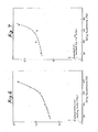
- the values of the electromechanical coupling factor K t are shown in Fig. 6 and the value of the piezoelectric constant d 31 of said piezoelectric bodies are shown in F ig. 7.
- Fig. 6 shows that when the piezoelectric bodies are heat-treated at a temperature of at least [T' m - 5]°C in advance, even though low temperatures are selected in the poling treatment, it is possible to produce piezoelectric bodies having the desired value of the electromechanical coupling factor K t .
- Fig. 6 shows that the piezoelectric bodies are heat-treated at a temperature of at least [T' m - 5]°C in advance, even though low temperatures are selected in the poling treatment, it is possible to produce piezoelectric bodies having the desired value of the electromechanical coupling factor K t .
- Fig. 6 shows that when the piezoelectric bodies are heat-treated at a temperature of at least [T' m - 5]°C in advance, even though low temperatures are selected in the poling treatment, it is possible to produce piezoelectric bodies having the desired value of the electromechanical coupling factor K t .
- the value of the elastic constant E 11 of the so obtained piezoelectric bodies are
- the piezoelectric bodies having large values of this elastic constant E 11 mean that when they are used as ultrasonic transducer utilizing the thickness piezoelectric properties of the piezoelectric bodies, they are advantageously used as good vibrators because their mechanical losses are small.
- a film obtained by heat pressing at 250°C having the composition ratio of VDF-TrFE of 75 - 25 mol % was rolled and drawn to about 2.5 times to obtain a drawn film having a thickness of about 50 ⁇ m.
- On the two surfaces of this drawn film was vacuum evaporated Al to form electrodes and the film was subjected to a poling treatment under coditions shown in Table 5.
- the value of the piezoelectric constant d 31 and the value of the electromechanical coupling factor K t of the obtained piezoelectric body are shown in Table 5.
- the melting point temperature T of the drawn film used in this example was about 148°C and the crystal phase transition temperature T' m of said film was about 130°C.
- the DSC curve of this film is shown in Fig. 8.
- a film obtained by hot pressing at 250°C having the composition ratio of VDF-TrFE 82 - 18 mol % was not drawn, but on the two surfaces of said film was vacuum evaporated Al to form electrodes and the film was subjected to poling treatment under conditions shown in Table 6.
- the values of the piezoelectric constant d 31 and values of the electromechanical coupling factor K t of the obtained piezoelectric bodies are shown in Table 6.
- the melting point temperature T m of the non-drawn film used in this comparative example and example was about 151°C and the crystal phase transition temperature T' m of said non-drawn film was about 123°C.
- the DSC curve of these temperature is shown in Fig. 9.
- This comparative example and example show that in the case of P(VDF-TrFE) having the composition ratio of VDF-TrFE of 82 - 18 mol %, Namely, within the range defined by the present invention, when the poling temperature imparting the heat-treatment effect is less than [T' m - 5]°C, namely, outside the range defined by the present invention, the value of the electromechanical coupling factor K t is 0.01, which is small, however, by selecting the poling temperature of at least [T ' m - 5]°C, further, T ' m per se (in thiscase, it is about 123°C as mentioned above), it is possible to produce a piezoelectric body having the value of the electromechanical coupling factor K t of 0.09, or an increased value.
- Fig. 10 is a graph showing a result obtained by measuring at room temperature the relation of the absolute value of the electric admitance in an acoustically non-load state of said thickness piezoelectric vibrator element and its phase angle, respectively with the frequency.
- the resonance peak at IYI - f curve (curve A) in Fig. 10 the difference from a valley in the vicinity of an anti-resonance point and the varied amount of the phase angle are larger than those of any hitherto known high polymer piezoelectric vibrator.
- Table 7 shows various constants obtained by comparing the admittance expected from the admittance of the vibrator.
- P(VDF-TrFE) has a K t value larger than that of PVDF, having dielectric loss and mechanical loss smaller than those of PVDF. This fact means that the efficiency at which electric energy (mechanical energy) put into the vibrator is converted to mechanical energy (electric energy) is good and the possibility that electric energy (mechanical energy) is converted to heat energy is small, showing that the vibrator is good.
- the element obtained in this example was adhered to one surface of a PMM A (polymethyl methacrylate) block (A) and a 6 mm PMMA plate (B) was adhered to the other surface to prepare a waterproof ultrasonic transducer.
- This transducer was immersed in water and at a position 3 mm forward the transducer, a 1. mm thick brass plate was placed in parallel to the PMMA plate (B).
- This transducer was excited with a short pulse to generate a ultrasonic pulse, the reflective signal of which was received by the same transducer.
- the thickness of the brass-plate could be measured by the signals of multi-reflection from the front and rear surface of-the brass plate. By this example, it was confirmed that this transducer generated ultrasonic wave having a practically sufficient intensity.
- the frequency characteristics of two kinds of conversion losses CL f and TL f by underwater driving of an ultrasonic transducer obtained by successively laminating a PMMA base plate, a copper plate (200 ⁇ m), P(VDF-TrFE) (area 1.32 cm 2 , thickness 80 ⁇ m) and a high polymer additional film (aromatic polyamide, 15 ⁇ m) were sought using a Mason's circuit.
- the effective area of the aforesaid transducer was 1 cm 2 and the copper plate concurrently acted as a back surface electrode and an acoustic reflective plate.
- confronting electrodes were provided on the surfaces of the P(VDF-TrFE) film.
- the values in Table 7 were used. The results are shown in Fig. 11.
- a 100 ⁇ m thick copper plate (radius 13 mm) shaped into a concave state by a mold having a radius of curvature of 70 mm was adhered, to which was adhered a 43 ⁇ m thick P(VDF-TrFE) piezoelectric film 4 (diameter 19 mm) having an Al vacuum evaporated electrode 3 on one surface, to the electrode 3 on the piezoelectirc film was electrically connected a metal case'for grounding 6, thereafter, onto the piezoelectric film was adhered a polyester film 5 (thickness 15 ⁇ m) for the purpose of protecting the surface and reducing the operating frequency ,and all of them was accomodated inside a plastic case 7.
- the piezoelectirc body made of P(VDF-TrFE) used in this example had a molar ratio of its components of 75/25, being obtained by vacuum evaporating Al on the two surfaces of a film drawn by rolls at 70°C and thereafter subjecting the film to a poling treatment at a poling temperature of 133°C, a poling voltage of 250 KV/cm for a poling time of 1 hour.
- the value of K t was found to be 0.24.
- a matching circuit consisting of a matching coil and an impedance conversion transformer was inserted between the power source and a piezoelectric element. As a result, it was possible remove the reflection between the transducer and power source.
- the loss (-101ogP Af /P 0 ) of the so matched transducer was 8.5 dB at 10 MHz.
Landscapes
- Physics & Mathematics (AREA)
- Spectroscopy & Molecular Physics (AREA)
- Manufacture Of Macromolecular Shaped Articles (AREA)
- Transducers For Ultrasonic Waves (AREA)
- Treatments Of Macromolecular Shaped Articles (AREA)
Applications Claiming Priority (4)
| Application Number | Priority Date | Filing Date | Title |
|---|---|---|---|
| JP13839/80 | 1980-02-07 | ||
| JP1383980A JPS56111281A (en) | 1980-02-07 | 1980-02-07 | High molecular piezoelectric body and manufacture thereof |
| JP1586080A JPS56114500A (en) | 1980-02-12 | 1980-02-12 | Ultrasonic transducer |
| JP15860/80 | 1980-02-12 |
Publications (2)
| Publication Number | Publication Date |
|---|---|
| EP0037877A1 true EP0037877A1 (de) | 1981-10-21 |
| EP0037877B1 EP0037877B1 (de) | 1984-09-19 |
Family
ID=26349691
Family Applications (1)
| Application Number | Title | Priority Date | Filing Date |
|---|---|---|---|
| EP81100836A Expired EP0037877B1 (de) | 1980-02-07 | 1981-02-05 | Piezoelektrisches Polymermaterial, Verfahren zu seiner Herstellung und dieses Material enthaltender Ultraschallwandler |
Country Status (5)
| Country | Link |
|---|---|
| US (1) | US4578442A (de) |
| EP (1) | EP0037877B1 (de) |
| AU (1) | AU544447B2 (de) |
| CA (1) | CA1183595A (de) |
| DE (1) | DE3166101D1 (de) |
Cited By (7)
| Publication number | Priority date | Publication date | Assignee | Title |
|---|---|---|---|---|
| FR2527622A1 (fr) * | 1982-05-28 | 1983-12-02 | Kureha Chemical Ind Co Ltd | Piece faconnee, polarisee, en copolymere de fluorure de vinylidene |
| DE3311040A1 (de) * | 1983-03-25 | 1984-09-27 | Siemens AG, 1000 Berlin und 8000 München | Ultraschall-sende/empfangs-system |
| FR2550904A1 (fr) * | 1983-08-16 | 1985-02-22 | Kureha Chemical Ind Co Ltd | Film piezoelectrique de polymere et procede pour sa fabrication |
| US4549107A (en) * | 1982-09-28 | 1985-10-22 | Tokyo Shibaura Denki Kabushiki Kaisha | Ultrasonic beam focusing device with a concave surface |
| EP0118757A3 (de) * | 1983-02-10 | 1987-10-07 | Daikin Kogyo Co., Ltd. | Polymeres ferroelektrisches Material |
| EP0207347A3 (de) * | 1985-07-01 | 1989-02-01 | Pennwalt Corporation | Faserfreies piezoelektrisches Polymer und sein Herstellungsverfahren |
| CN110462859A (zh) * | 2017-01-26 | 2019-11-15 | 理想星株式会社 | 压电膜及其制造方法 |
Families Citing this family (18)
| Publication number | Priority date | Publication date | Assignee | Title |
|---|---|---|---|---|
| US4830795A (en) * | 1986-07-03 | 1989-05-16 | Rutgers, The State University Of New Jersey | Process for making polarized material |
| US4863648A (en) * | 1986-07-03 | 1989-09-05 | Rutgers, The State University Of New Jersey | Process for making polarized material |
| US4778867A (en) * | 1987-07-21 | 1988-10-18 | Seymour Pries | Ferroelectric copolymers of vinylidene fluoride and trifluoroethylene with increased Curie temperature and their methods of production |
| JPH0796607B2 (ja) * | 1987-09-07 | 1995-10-18 | 富山県 | 高分子圧電材及びその製造方法 |
| JP2585018B2 (ja) * | 1987-09-08 | 1997-02-26 | 富山県 | 圧電型感圧素子及びその製造方法 |
| JPH02197183A (ja) * | 1988-03-29 | 1990-08-03 | Pennwalt Corp | 積層圧電構造及びその形成方法 |
| JP3742574B2 (ja) * | 2001-09-10 | 2006-02-08 | 弘二 大東 | 強誘電性高分子膜の製造方法 |
| SE0200860D0 (sv) * | 2002-03-20 | 2002-03-20 | Monica Almqvist | Microfluidic cell and method for sample handling |
| JP2008188415A (ja) * | 2007-01-09 | 2008-08-21 | Konica Minolta Medical & Graphic Inc | 圧電素子、その製造方法、及び当該圧電素子を具備する超音波探触子 |
| WO2009114847A1 (en) * | 2008-03-14 | 2009-09-17 | Cidra Corporate Services, Inc. | Flow and pipe management using velocity profile measurement and/or pipe wall thickness and wear monitoring |
| JP5780910B2 (ja) * | 2011-10-03 | 2015-09-16 | オリンパス株式会社 | 円筒型圧電素子の製造方法 |
| US20130277305A1 (en) * | 2012-04-19 | 2013-10-24 | Lockheed Martin Corporation | Selectively perforated graphene membranes for compound harvest, capture and retention |
| JP6633834B2 (ja) * | 2015-04-02 | 2020-01-22 | 株式会社イデアルスター | 圧電膜、およびその製造方法 |
| GB201617171D0 (en) | 2016-10-10 | 2016-11-23 | Universitetet I Troms� - Norges Arktiske Universitet | Piezoelectric films |
| CN109494295A (zh) * | 2017-09-12 | 2019-03-19 | 南昌欧菲生物识别技术有限公司 | 压电元件、超声波传感器及电子装置 |
| CN110752286B (zh) * | 2019-10-25 | 2023-04-07 | 业成科技(成都)有限公司 | 压电薄膜及其制备方法和压电薄膜传感器 |
| CN112538182A (zh) * | 2020-12-03 | 2021-03-23 | 江西欧迈斯微电子有限公司 | 压电膜、其制备方法、指纹识别模组及电子设备 |
| CN114614193B (zh) * | 2022-03-25 | 2023-06-06 | 中南大学 | 一种极化复合隔膜及其制备和应用 |
Citations (1)
| Publication number | Priority date | Publication date | Assignee | Title |
|---|---|---|---|---|
| US3798473A (en) * | 1971-11-05 | 1974-03-19 | Kureha Chemical Ind Co Ltd | Polymer type electroacoustic transducer element |
Family Cites Families (10)
| Publication number | Priority date | Publication date | Assignee | Title |
|---|---|---|---|---|
| BE464137A (de) * | 1944-09-19 | |||
| JPS5029159B1 (de) * | 1970-12-02 | 1975-09-20 | ||
| GB1367738A (en) * | 1971-07-20 | 1974-09-25 | Kureha Chemical Ind Co Ltd | Process for the production of polyvinylidene fluoride resin film |
| US3803108A (en) * | 1972-06-12 | 1974-04-09 | Pennwalt Corp | Polyvinylidene fluoride powder |
| JPS5326995A (en) * | 1976-08-25 | 1978-03-13 | Daikin Ind Ltd | Highhmolecular piezooelectric material |
| GB2033147B (en) * | 1978-09-21 | 1982-12-15 | Tokyo Shibaura Electric Co | Method for production of composite piezoelectric material |
| JPS5569902A (en) * | 1978-11-21 | 1980-05-27 | Kureha Chemical Ind Co Ltd | Preparing piezoelectric* electrically scorchable film |
| US4241128A (en) * | 1979-03-20 | 1980-12-23 | Bell Telephone Laboratories, Incorporated | Production of piezoelectric PVDF films |
| DE3011736A1 (de) * | 1979-03-26 | 1980-10-09 | Daikin Ind Ltd | Polymeres piezoelektrisches material und verfahren zu dessen herstellung |
| JPS606220B2 (ja) * | 1979-04-11 | 1985-02-16 | 三菱油化株式会社 | ポリ弗化ビニリデンもしくは弗化ビニリデン共重合体の延伸薄膜製造法 |
-
1981
- 1981-02-05 DE DE8181100836T patent/DE3166101D1/de not_active Expired
- 1981-02-05 EP EP81100836A patent/EP0037877B1/de not_active Expired
- 1981-02-05 AU AU66933/81A patent/AU544447B2/en not_active Ceased
- 1981-02-06 CA CA000370378A patent/CA1183595A/en not_active Expired
-
1983
- 1983-07-05 US US06/510,687 patent/US4578442A/en not_active Expired - Fee Related
Patent Citations (1)
| Publication number | Priority date | Publication date | Assignee | Title |
|---|---|---|---|---|
| US3798473A (en) * | 1971-11-05 | 1974-03-19 | Kureha Chemical Ind Co Ltd | Polymer type electroacoustic transducer element |
Cited By (13)
| Publication number | Priority date | Publication date | Assignee | Title |
|---|---|---|---|---|
| DE3318871A1 (de) * | 1982-05-28 | 1983-12-08 | Kureha Kagaku Kogyo K.K., Nihonbashi, Tokyo | Polarisierter geformter gegenstand aus einem copolymeren des vinylidenfluorids |
| GB2121810A (en) * | 1982-05-28 | 1984-01-04 | Kureha Chemical Ind Co Ltd | Polarised films of vinylidene fluoride copolymers |
| FR2527622A1 (fr) * | 1982-05-28 | 1983-12-02 | Kureha Chemical Ind Co Ltd | Piece faconnee, polarisee, en copolymere de fluorure de vinylidene |
| US4543293A (en) * | 1982-05-28 | 1985-09-24 | Kureha Kagaku Kogyo Kabushiki Kaisha | Polarized, shaped material of copolymer of vinylidene fluoride |
| US4549107A (en) * | 1982-09-28 | 1985-10-22 | Tokyo Shibaura Denki Kabushiki Kaisha | Ultrasonic beam focusing device with a concave surface |
| EP0118757A3 (de) * | 1983-02-10 | 1987-10-07 | Daikin Kogyo Co., Ltd. | Polymeres ferroelektrisches Material |
| DE3311040A1 (de) * | 1983-03-25 | 1984-09-27 | Siemens AG, 1000 Berlin und 8000 München | Ultraschall-sende/empfangs-system |
| FR2550904A1 (fr) * | 1983-08-16 | 1985-02-22 | Kureha Chemical Ind Co Ltd | Film piezoelectrique de polymere et procede pour sa fabrication |
| US4784915A (en) * | 1983-08-16 | 1988-11-15 | Kureha Kagaku Kogyo Kabushiki Kaisha | Polymer piezoelectric film |
| EP0207347A3 (de) * | 1985-07-01 | 1989-02-01 | Pennwalt Corporation | Faserfreies piezoelektrisches Polymer und sein Herstellungsverfahren |
| CN110462859A (zh) * | 2017-01-26 | 2019-11-15 | 理想星株式会社 | 压电膜及其制造方法 |
| EP3576171A4 (de) * | 2017-01-26 | 2020-12-30 | Ideal Star Inc. | Piezoelektrische schicht und verfahren zur herstellung davon |
| CN110462859B (zh) * | 2017-01-26 | 2023-03-28 | 理想星株式会社 | 压电膜及其制造方法 |
Also Published As
| Publication number | Publication date |
|---|---|
| AU544447B2 (en) | 1985-05-30 |
| AU6693381A (en) | 1981-08-13 |
| US4578442A (en) | 1986-03-25 |
| DE3166101D1 (en) | 1984-10-25 |
| EP0037877B1 (de) | 1984-09-19 |
| CA1183595A (en) | 1985-03-05 |
Similar Documents
| Publication | Publication Date | Title |
|---|---|---|
| EP0037877B1 (de) | Piezoelektrisches Polymermaterial, Verfahren zu seiner Herstellung und dieses Material enthaltender Ultraschallwandler | |
| US4577132A (en) | Ultrasonic transducer employing piezoelectric polymeric material | |
| Fukada | History and recent progress in piezoelectric polymers | |
| Ohigashi et al. | Piezoelectric and ferroelectric properties of P (VDF-TrFE) copolymers and their application to ultrasonic transducers | |
| US4877988A (en) | Piezoelectric and pyroelectric polymers | |
| US5539965A (en) | Method for making piezoelectric composites | |
| Qiu | Patterned piezo-, pyro-, and ferroelectricity of poled polymer electrets | |
| Smith | Optimizing electromechanical coupling in piezocomposites using polymers with negative Poisson's ratio | |
| US4500377A (en) | Process for the production of a block of piezoelectric macromolecular material | |
| JPWO2010104196A1 (ja) | 高分子圧電材料、及びその製造方法、並びに、圧電素子 | |
| Bauer | Relaxor fluorinated polymers: novel applications and recent developments | |
| Schlaberg et al. | Piezoelectric polymer composite arrays for ultrasonic medical imaging applications | |
| GB2145106A (en) | Polymer piezoelectric film and process for producing the same | |
| KR20220116302A (ko) | 압전 필름 | |
| Patel | Ceramic based intelligent piezoelectric energy harvesting device | |
| JP3360371B2 (ja) | 横波振動素子、表面波圧電素子および超音波トランスデューサ | |
| Tressler et al. | A comparison of the underwater acoustic performance of single crystal versus piezoelectric ceramic-based “cymbal” projectors | |
| McGrath et al. | Recent measurements on improved thick film piezoelectric PVDF polymer materials for hydrophone applications | |
| US4692285A (en) | Process of preparing nonfibrous, piezoelectric polymer sheet of improved activity | |
| Chilibon et al. | PZT and PVDF bimorph actuators | |
| Cheng et al. | Design, fabrication, and performance of a flextensional transducer based on electrostrictive polyvinylidene fluoride-trifluoroethylene copolymer | |
| Chilibon | Underwater flextensional piezoceramic sandwich transducer | |
| Chan et al. | Piezoelectric ceramic/polymer composites for high frequency applications | |
| JPS6242560B2 (de) | ||
| Omote et al. | Shear piezoelectric properties of vinylidene fluoride trifluoroethylene copolymer, and its application to transverse ultrasonic transducers |
Legal Events
| Date | Code | Title | Description |
|---|---|---|---|
| PUAI | Public reference made under article 153(3) epc to a published international application that has entered the european phase |
Free format text: ORIGINAL CODE: 0009012 |
|
| AK | Designated contracting states |
Designated state(s): CH DE FR GB NL |
|
| RBV | Designated contracting states (corrected) |
Designated state(s): CH DE FR GB LI NL |
|
| 17P | Request for examination filed |
Effective date: 19820330 |
|
| GRAA | (expected) grant |
Free format text: ORIGINAL CODE: 0009210 |
|
| AK | Designated contracting states |
Designated state(s): CH DE FR GB LI NL |
|
| REF | Corresponds to: |
Ref document number: 3166101 Country of ref document: DE Date of ref document: 19841025 |
|
| ET | Fr: translation filed | ||
| PLBE | No opposition filed within time limit |
Free format text: ORIGINAL CODE: 0009261 |
|
| STAA | Information on the status of an ep patent application or granted ep patent |
Free format text: STATUS: NO OPPOSITION FILED WITHIN TIME LIMIT |
|
| 26N | No opposition filed | ||
| PGFP | Annual fee paid to national office [announced via postgrant information from national office to epo] |
Ref country code: GB Payment date: 19940126 Year of fee payment: 14 |
|
| PGFP | Annual fee paid to national office [announced via postgrant information from national office to epo] |
Ref country code: DE Payment date: 19940209 Year of fee payment: 14 |
|
| PGFP | Annual fee paid to national office [announced via postgrant information from national office to epo] |
Ref country code: FR Payment date: 19940210 Year of fee payment: 14 |
|
| PGFP | Annual fee paid to national office [announced via postgrant information from national office to epo] |
Ref country code: CH Payment date: 19940215 Year of fee payment: 14 |
|
| PGFP | Annual fee paid to national office [announced via postgrant information from national office to epo] |
Ref country code: NL Payment date: 19940228 Year of fee payment: 14 |
|
| PG25 | Lapsed in a contracting state [announced via postgrant information from national office to epo] |
Ref country code: GB Effective date: 19950205 |
|
| PG25 | Lapsed in a contracting state [announced via postgrant information from national office to epo] |
Ref country code: LI Effective date: 19950228 Ref country code: CH Effective date: 19950228 |
|
| PG25 | Lapsed in a contracting state [announced via postgrant information from national office to epo] |
Ref country code: NL Effective date: 19950901 |
|
| GBPC | Gb: european patent ceased through non-payment of renewal fee |
Effective date: 19950205 |
|
| PG25 | Lapsed in a contracting state [announced via postgrant information from national office to epo] |
Ref country code: FR Effective date: 19951031 |
|
| NLV4 | Nl: lapsed or anulled due to non-payment of the annual fee |
Effective date: 19950901 |
|
| PG25 | Lapsed in a contracting state [announced via postgrant information from national office to epo] |
Ref country code: DE Effective date: 19951101 |
|
| REG | Reference to a national code |
Ref country code: FR Ref legal event code: ST |