EP0037961A2 - Keramischer Brennerkopf mit zum Brennermund parallel zueinander geführten, schlitzförmigen Strömungskanälen für Brennstoff und Oxidationsmittel - Google Patents
Keramischer Brennerkopf mit zum Brennermund parallel zueinander geführten, schlitzförmigen Strömungskanälen für Brennstoff und Oxidationsmittel Download PDFInfo
- Publication number
- EP0037961A2 EP0037961A2 EP81102448A EP81102448A EP0037961A2 EP 0037961 A2 EP0037961 A2 EP 0037961A2 EP 81102448 A EP81102448 A EP 81102448A EP 81102448 A EP81102448 A EP 81102448A EP 0037961 A2 EP0037961 A2 EP 0037961A2
- Authority
- EP
- European Patent Office
- Prior art keywords
- fuel
- flow channels
- burner
- burner head
- mouthpiece
- Prior art date
- Legal status (The legal status is an assumption and is not a legal conclusion. Google has not performed a legal analysis and makes no representation as to the accuracy of the status listed.)
- Granted
Links
Images

Classifications
-
- F—MECHANICAL ENGINEERING; LIGHTING; HEATING; WEAPONS; BLASTING
- F23—COMBUSTION APPARATUS; COMBUSTION PROCESSES
- F23D—BURNERS
- F23D11/00—Burners using a direct spraying action of liquid droplets or vaporised liquid into the combustion space
- F23D11/36—Details
- F23D11/44—Preheating devices; Vaporising devices
- F23D11/441—Vaporising devices incorporated with burners
-
- F—MECHANICAL ENGINEERING; LIGHTING; HEATING; WEAPONS; BLASTING
- F23—COMBUSTION APPARATUS; COMBUSTION PROCESSES
- F23D—BURNERS
- F23D14/00—Burners for combustion of a gas, e.g. of a gas stored under pressure as a liquid
- F23D14/46—Details
- F23D14/62—Mixing devices; Mixing tubes
Definitions
- the invention relates to a ceramic burner head with slit-shaped flow channels for fuel and oxidizing agent which are guided parallel to one another to the burner mouth and which are arranged adjacent to one another and have partition walls made of porous material permeable to the fuel between them in the region of the burner mouth.
- Ceramic burner heads of this type are intended for use in industrial furnaces as well as for small-scale heat generators. They are suitable for gaseous but also liquid fuels.
- liquid fuels When using liquid fuels, the fuel is evaporated before it exits the burner mouth by preheating the oxidizing agent and corresponding heat exchange between the oxidizing agent and the liquid fuel in the flow channels in the ceramic burner head.
- the liquid fuel penetrates the porous partition walls between the flow channels in the area of the burner mouth and is taken up by the preheated combustion air.
- undesirable overheating of the fuel which leads to cracking, is prevented.
- fuel and combustion air are mixed together and led to the burner mouth as an ignitable mixture.
- the object of the invention is to simplify the design of the burner head with porous partition walls between the flow channels for oxidizing agent and fuel in the area of the burner mouth.
- a mouthpiece which is made of porous material that is permeable to the fuel, is then embedded in the mouthpiece in a gas-tight surrounding outer walls on the burner mouth.
- the mouthpiece is advantageously independent of the design of the oxidant and fuel-carrying flow channels can be formed and can be adapted to the desired shape of the mouths of the flow channels, which is appropriate for the particular purpose of the burner head.
- the mouthpiece is arranged in the burner head at a distance from the flow channels for the oxidizing agent.
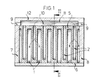
- the burner head has slot-shaped flow channels 1, 2 for fuel and oxidizing agent which are guided parallel to one another.
- preheated combustion air is conducted in the flow channel 1 and fuel is conducted in the flow channel 2.
- Gaseous or liquid fuels can be used.
- the flow channels 2 for the fuel are at the burner mouth 3 with end pieces 4 locked.
- a mouthpiece 5 is used on the burner mouth, which consists of porous material which is permeable to the fuel.
- the mouthpiece is embedded in gas-tight covers 6, 7, 8, 9, which - except for cover 9 - complete the ceramic burner head as outer walls in the exemplary embodiment.
- a recess 10 is provided in the cover 9, through which the fuel which is guided in a channel 11 in the ceiling part 12 of the ceramic burner head can flow into the flow channels 2 of the mouthpiece 5.
- Combustion air is supplied to the ceramic burner head through flow channels 1 '.
- the direction of flow of the air is indicated in FIG. 2 by an arrow drawn with dashed lines.
- the flow channels 1 ' form the part of a countercurrent heat exchanger in which the combustion air is preheated.
- Exhaust gas is advantageously used for preheating, which is guided in the countercurrent heat exchanger in exhaust gas channels which run parallel to the flow channels 1 'and which are not shown separately in the drawing.
- the exhaust gas is introduced in the counterflow heat exchanger at the inlet 13.
- the mouthpiece 5 is arranged at a distance 14 from the end of the flow channels 1 'in the ceramic burner head.
- the distance is a multiple of the slot width of the flow channels 1 ', so that the flow in the space 15 thus created between the end of the flow channels 1' and the adjoining mouthpiece 5 guide the combustion air to the burner mouth.
- the fuel channels 2 in the mouthpiece 5 are closed towards the space 15 by end pieces 16.
- the fuel flowing into the flow channels 2 passes through the porous walls of the mouthpiece 5 into the flow channels 1 and mixes with the preheated combustion air flowing there to form an ignitable mixture which is led to the burner mouth 3 and ignited in the combustion chamber.
- the mouthpiece 5 is inserted in the covers 6, 7, 8, 9 with slip mass.
- the ceramic burner head is re-fired for a gas-tight connection of the mouthpiece with the covers.
Landscapes
- Engineering & Computer Science (AREA)
- Chemical & Material Sciences (AREA)
- Combustion & Propulsion (AREA)
- Mechanical Engineering (AREA)
- General Engineering & Computer Science (AREA)
- Gas Burners (AREA)
- Spray-Type Burners (AREA)
- Pre-Mixing And Non-Premixing Gas Burner (AREA)
- Air Supply (AREA)
Abstract
Description
- Die Erfindung bezieht sich auf einen keramischen Brennerkopf mit zum Brennermund parallel zueinander geführten, schlitzförmigen Strömungskanälen für Brennstoff und Oxidationsmittel, die benachbart angeordnet sind und zwischen sich im Bereich des Brennermundes Trennwände aus für den Brennstoff durchlässigem, porösem Werkstoff aufweisen.
- Keramische Brennerköpfe dieser Art sind sowohl für den Einsatz in Industrieöfen als auch für Wärmeerzeuger kleinerer Einheit bestimmt. Sie sind für gasförmige aber auch flüssige Brennstoffe geeignet. Bei Verwendung flüssiger Brennstoffe wird der Brennstoff vor Austritt am Brennermund durch Vorwärmen des Oxidationsmittels und entsprechendem Wärmeaustausch zwischen Oxidationsmittel und flüssigem Brennstoff in den Strömungskanälen im keramischen Brennerkopf verdunstet. Der flüssige Brennstoff durchdringt die porösen Trennwände zwischen den Strömungskanälen im Bereich des Brennermundes und wird von der vorgewärmten Verbrennungsluft aufgenommen. Infolge der Verdunstung des flüssigen Brennstoffs auf der Oberfläche der porösen Wände wird eine unerwünschte überhitzung des Brennstoffs, die zum Cracken führt, verhindert. Im Strömungskanal für die Verbrennungsluft werden Brennstoff und Verbrennungsluft miteinander vermischt und als zündfähiges Gemisch zum Brennermund geführt.
- Aufgabe der Erfindung ist es,die Ausbildung des Brennerkopfes mit porösen Trennwänden zwischen den Strömungskanälen für Oxidationsmittel und Brennstoff im Bereich des Brennermundes zu vereinfachen.
- Diese Aufgabe wird bei einem keramischen Brennerkopf der eingangs erwähnten Art durch die im Patentanspruch 1 angegebene Ausbildung gelöst. Danach ist am Brennermund ein Mundstück, das aus für den Brennstoff durchlässigem, porösem Werkstoff besteht, in das Mundstück gasdicht umschließenden Außenwänden eingebettet. Das Mundstück ist in vorteilhafter Weise unabhängig von der Ausgestaltung der Oxidationsmittel und Brennstoff führenden Strömungskanäle ausbildbar und kann der gewünschten, für den jeweiligen Verwendungszweck des Brennerkopfes zweckmäßigen Form der Mündungen der Strömungskanäle angepaßt werden.
- Um Schwierigkeiten beim Anschluß des porösen Mundstücks an den die Verbrennungsluft führenden Strömungskanälen zu vermeiden, ist das Mundstück im Brennerkopf mit Abstand zu den Strömungskanälen für das Oxidationsmittel angeordnet, Patentanspruch 2.
- Die Erfindung wird anhand eines in der Zeichnung dargestellten Ausführungsbeispieles näher erläutert. Es zeigen im einzelnen
- Figur 1 Querschnitt durch einen keramischen Brennerkopf mit einem im Brennermund eingebetteten Mundstück, gemäß Schnittlinie I/I nach Figur 2
- Figur 2 Längsschnitt durch einen keramischen Brennerkopf nach Figur 1 gemäß Schnittlinie II/II.
- Wie aus der Zeichnung ersichtlich ist, weist der Brennerkopf parallel zueinander geführte, schlitzförmige Strömungskanäle 1, 2 für Brennstoff und Oxidationsmittel auf. Im Ausführungsbeispiel wird im Strömungskanal 1 vorgewärmte Verbrennungsluft, im Strömungskanal 2 Brennstoff geführt. Es können gasförmige oder flüssige Brennstoffe verwendet werden. Die Strömungskanäle 2 für den Brennstoff sind am Brennermund 3 mit Endstücken 4 verschlossen. Am Brennermund ist ein Mundstück 5 eingesetzt, das aus für den Brennstoff durchlässigem, porösem Werkstoff besteht. Das Mundstück ist in gasdichten Abdeckungen 6, 7 , 8, 9 eingebettet, die - bis auf die Abdeckung 9 - im Ausführungsbeispiel den keramischen Brennerkopf als Außenwände abschließen. In der Abdeckung 9 ist eine Ausnehmung 1o vorgesehen, durch die der Brennstoff, der in einem Kanal 11 im Deckenteil 12 des keramischen Brennerkopfes geführt wird, in die Strömungskanäle 2 des Mundstücks 5 einströmen kann.
- Durch Strömungskanäle 1' wird dem keramischen Brennerkopf Verbrennungsluft zugeführt. Die Strömungsrichtung der Luft ist in Figur 2 durch einen mit gestrichelten Linien gezeichneten Pfeil angegeben. Die Strömungskanäle 1' bilden im Ausführungsbeispiel den Teil eines Gegenstromwärmetauschers, in dem die Verbrennungsluft vorerhitzt wird. Zur Vorerhitzung dient zweckmäßig Abgas, das in dem Gegenstromwärmetauscher in parallel zu den Strömungskanälen 1' verlaufenden Abgaskanälen geführt ist, die in der Zeichnung nicht gesondert dargestellt sind. Das Abgas wird im Gegenstromwärmetauscher am Zugang 13 eingeführt.
- Das Mundstück 5 ist mit Abstand 14 vom Ende der Strömungskanäle 1' im keramischen Brennerkopf angeordnet. Der Abstand beträgt ein mehrfaches der Schlitzbreite der Strömungskanäle 1', um in dem auf diese Weise entstehenden Zwischenraum 15 zwischen dem Ende der Strömungskanäle 1' und dem sich anschließenden Mundstück 5 die Strömungsführung der Verbrennungsluft zum Brennermund zu vergleichmäßigen.
- Die den Brennstoff führenden Strömungskanäle 2 im Mundstück 5 sind zum Zwischenraum 15 hin durch Endstücke 16 verschlossen. Der in die Strömungskanäle 2 einströmende Brennstoff gelangt durch die porösen Wände des Mundstücks 5 hindurch in die Strömungskanäle 1 und vermischt sich mit der dort strömenden vorgewärmten Verbrennungsluft zu einem zündfähigen Gemisch, das zum Brennermund 3 geführt und im Brennraum gezündet wird.
- Das Mundstück 5 ist in den Abdeckungen 6, 7, 8, 9 mit Schlickermasse eingesetzt. Zur gasdichten Verbindung des Mundstücks mit den Abdeckungen wird der keramische Brennerkopf nachgebrannt.
Claims (2)
Priority Applications (1)
| Application Number | Priority Date | Filing Date | Title |
|---|---|---|---|
| AT81102448T ATE10780T1 (de) | 1980-04-11 | 1981-04-01 | Keramischer brennerkopf mit zum brennermund parallel zueinander gefuehrten, schlitzfoermigen stroemungskanaelen fuer brennstoff und oxidationsmittel. |
Applications Claiming Priority (2)
| Application Number | Priority Date | Filing Date | Title |
|---|---|---|---|
| DE3014059A DE3014059C2 (de) | 1980-04-11 | 1980-04-11 | Keramischer Brennerkopf mit zum Brennermund parallel zueinander geführten, schlitzförmigen Strömungskanälen für Brennstoff und Oxidationsmittel |
| DE3014059 | 1980-04-11 |
Publications (3)
| Publication Number | Publication Date |
|---|---|
| EP0037961A2 true EP0037961A2 (de) | 1981-10-21 |
| EP0037961A3 EP0037961A3 (en) | 1982-09-01 |
| EP0037961B1 EP0037961B1 (de) | 1984-12-12 |
Family
ID=6099818
Family Applications (1)
| Application Number | Title | Priority Date | Filing Date |
|---|---|---|---|
| EP81102448A Expired EP0037961B1 (de) | 1980-04-11 | 1981-04-01 | Keramischer Brennerkopf mit zum Brennermund parallel zueinander geführten, schlitzförmigen Strömungskanälen für Brennstoff und Oxidationsmittel |
Country Status (5)
| Country | Link |
|---|---|
| US (1) | US4531908A (de) |
| EP (1) | EP0037961B1 (de) |
| JP (1) | JPS5712213A (de) |
| AT (1) | ATE10780T1 (de) |
| DE (1) | DE3014059C2 (de) |
Cited By (4)
| Publication number | Priority date | Publication date | Assignee | Title |
|---|---|---|---|---|
| GB2140154A (en) * | 1983-02-16 | 1984-11-21 | Melda Enterprises | Simulated solid fuel gas fires |
| FR2608455A1 (fr) * | 1986-12-23 | 1988-06-24 | Inst Francais Du Petrole | Dispositif d'introduction de gaz comprenant des tubes comportant des zones retreintes |
| DE10042761C1 (de) * | 2000-06-20 | 2001-09-13 | Bosch Gmbh Robert | Rekuperativer Brenner mit Gasleitvorrichtung |
| DE10149329A1 (de) * | 2001-10-06 | 2003-04-24 | Bosch Gmbh Robert | Integrierter rekuperativer Brenner |
Families Citing this family (2)
| Publication number | Priority date | Publication date | Assignee | Title |
|---|---|---|---|---|
| JPS62294805A (ja) * | 1987-05-22 | 1987-12-22 | Nippon Chem Plant Consultant:Kk | 燃焼器における燃料混合器 |
| DE19740625A1 (de) * | 1997-09-16 | 1999-03-18 | Ruhrgas Ag | Flächenbrenner |
Family Cites Families (10)
| Publication number | Priority date | Publication date | Assignee | Title |
|---|---|---|---|---|
| US742879A (en) * | 1902-11-03 | 1903-11-03 | James J Lawler | Porous brick for heating purposes. |
| GB1247406A (en) * | 1969-04-28 | 1971-09-22 | British Petroleum Co | Wick burner |
| US3650661A (en) * | 1969-11-13 | 1972-03-21 | Enrique L Laguinia | Liquid fuel burner |
| JPS4827655A (de) * | 1971-08-12 | 1973-04-12 | ||
| NL7314826A (de) * | 1972-12-11 | 1974-06-13 | ||
| JPS504268U (de) * | 1973-05-10 | 1975-01-17 | ||
| JPS5333903A (en) * | 1976-09-10 | 1978-03-30 | Nippon Steel Corp | Burner for heat regeneration type hot stove |
| DE2853309C2 (de) * | 1978-12-09 | 1984-04-05 | Kernforschungsanlage Jülich GmbH, 5170 Jülich | Keramischer Brennerkopf für gasförmigen Brennstoff |
| DE2912518A1 (de) * | 1979-03-29 | 1980-10-16 | Kernforschungsanlage Juelich | Keramischer brennerkopf mit zum brennermund parallel zueinander gefuehrten stroemungskanaelen fuer brennstoff und oxidationsmittel |
| EP0017156B1 (de) * | 1979-03-29 | 1983-10-12 | Forschungszentrum Jülich Gmbh | Keramischer Brennerkopf mit zum Brennermund parallel zueinander geführten Strömungskanälen für Brennstoff und Oxidationsmittel |
-
1980
- 1980-04-11 DE DE3014059A patent/DE3014059C2/de not_active Expired
-
1981
- 1981-04-01 AT AT81102448T patent/ATE10780T1/de active
- 1981-04-01 EP EP81102448A patent/EP0037961B1/de not_active Expired
- 1981-04-10 JP JP5309181A patent/JPS5712213A/ja active Granted
-
1982
- 1982-07-16 US US06/398,797 patent/US4531908A/en not_active Expired - Fee Related
Cited By (6)
| Publication number | Priority date | Publication date | Assignee | Title |
|---|---|---|---|---|
| GB2140154A (en) * | 1983-02-16 | 1984-11-21 | Melda Enterprises | Simulated solid fuel gas fires |
| FR2608455A1 (fr) * | 1986-12-23 | 1988-06-24 | Inst Francais Du Petrole | Dispositif d'introduction de gaz comprenant des tubes comportant des zones retreintes |
| EP0275780A1 (de) * | 1986-12-23 | 1988-07-27 | Institut Français du Pétrole | Gaszuführapparat, bestehend aus Röhren mit Einschnürungsbereichen |
| DE10042761C1 (de) * | 2000-06-20 | 2001-09-13 | Bosch Gmbh Robert | Rekuperativer Brenner mit Gasleitvorrichtung |
| DE10149329A1 (de) * | 2001-10-06 | 2003-04-24 | Bosch Gmbh Robert | Integrierter rekuperativer Brenner |
| DE10149329C2 (de) * | 2001-10-06 | 2003-08-21 | Bosch Gmbh Robert | Integrierter rekuperativer Brenner |
Also Published As
| Publication number | Publication date |
|---|---|
| JPH0132882B2 (de) | 1989-07-11 |
| JPS5712213A (en) | 1982-01-22 |
| ATE10780T1 (de) | 1984-12-15 |
| EP0037961A3 (en) | 1982-09-01 |
| US4531908A (en) | 1985-07-30 |
| DE3014059C2 (de) | 1985-12-19 |
| DE3014059A1 (de) | 1981-11-19 |
| EP0037961B1 (de) | 1984-12-12 |
Similar Documents
| Publication | Publication Date | Title |
|---|---|---|
| DE2416434A1 (de) | Verkokungsofen | |
| DE3780600T2 (de) | Verfahren und vorrichtung zum herstellung von synthesegas mittels einer flamme. | |
| DE2853309C2 (de) | Keramischer Brennerkopf für gasförmigen Brennstoff | |
| DE3339972C2 (de) | Kammerringofen und Verfahren zu dessen Betrieb | |
| EP0037961B1 (de) | Keramischer Brennerkopf mit zum Brennermund parallel zueinander geführten, schlitzförmigen Strömungskanälen für Brennstoff und Oxidationsmittel | |
| DE1252850B (de) | Verfahren zum Brennen und Kuehlen von koernigem Gut, z. B. von Kalkstein, und Ofen zur Durchfuehrung des Verfahrens | |
| DE2164994C3 (de) | Rekuperativkoksofen | |
| AT386885B (de) | Vormisch-brenneranordnung | |
| DE491291C (de) | Kammerofen mit senkrechten Heizzuegen und auf den Zufuehrungsoeffnungen fuer Luft oder Heizgas und Luft angeordneten Schiebersteinen | |
| DE3149484C2 (de) | Beheizungssystem zur regenerativen Beheizung einer Koksofenbatterie mit Zwillingsheizzügen | |
| DE2002635A1 (de) | Brenner fuer gasfoermige und fluessige Brennstoffe | |
| AT47643B (de) | Einrichtung zum Mischen der Heizgase und der Verbrennungsluft bei Gaserzeugungsöfen. | |
| DE447732C (de) | Senkrechter Regenerativ-Kammerofen zur Erzeugung von Gas und Koks | |
| EP0082309A1 (de) | Keramischer Brenner für einen Winderhitzer | |
| DE415845C (de) | Koksofen mit stehenden Kammern | |
| DE174313C (de) | ||
| DE248523C (de) | ||
| DE462801C (de) | Regenerativgas-Gleichstromofen | |
| DE589395C (de) | Regenerativflammofen mit kalter Koksgasbeheizung | |
| DE1526027A1 (de) | Brenner fuer Winderhitzer mit innenliegendem Brennschacht | |
| AT89917B (de) | Kanalofen zum Brennen oder Emaillieren von Töpferwaren u. dgl. | |
| DE1262961B (de) | Halbgeteilter Regenerativ-Verbundkoksofen | |
| DE3111476A1 (de) | "batterieweise angeordneter kammerofen zur erzeugungvon koks und gas" | |
| DE582379C (de) | Regenerativkoksofen mit abwechselnd beflammten unteren und oberen Brennstellen | |
| DE340717C (de) | Gasheizofen mit Luftumlauf und Oberflaechenverbrennung des Heizgases |
Legal Events
| Date | Code | Title | Description |
|---|---|---|---|
| PUAI | Public reference made under article 153(3) epc to a published international application that has entered the european phase |
Free format text: ORIGINAL CODE: 0009012 |
|
| AK | Designated contracting states |
Designated state(s): AT BE CH FR GB IT LU NL SE |
|
| RAP1 | Party data changed (applicant data changed or rights of an application transferred) |
Owner name: ROSENTHAL TECHNIK AG Owner name: KERNFORSCHUNGSANLAGE JUELICH GESELLSCHAFT MIT BESC |
|
| PUAL | Search report despatched |
Free format text: ORIGINAL CODE: 0009013 |
|
| AK | Designated contracting states |
Designated state(s): AT BE CH FR GB IT LU NL SE |
|
| 17P | Request for examination filed |
Effective date: 19830226 |
|
| ITF | It: translation for a ep patent filed | ||
| GRAA | (expected) grant |
Free format text: ORIGINAL CODE: 0009210 |
|
| AK | Designated contracting states |
Designated state(s): AT BE CH FR GB IT LI LU NL SE |
|
| REF | Corresponds to: |
Ref document number: 10780 Country of ref document: AT Date of ref document: 19841215 Kind code of ref document: T |
|
| ET | Fr: translation filed | ||
| PG25 | Lapsed in a contracting state [announced via postgrant information from national office to epo] |
Ref country code: LU Free format text: LAPSE BECAUSE OF NON-PAYMENT OF DUE FEES Effective date: 19850430 |
|
| PLBE | No opposition filed within time limit |
Free format text: ORIGINAL CODE: 0009261 |
|
| STAA | Information on the status of an ep patent application or granted ep patent |
Free format text: STATUS: NO OPPOSITION FILED WITHIN TIME LIMIT |
|
| 26N | No opposition filed | ||
| PGFP | Annual fee paid to national office [announced via postgrant information from national office to epo] |
Ref country code: GB Payment date: 19890331 Year of fee payment: 9 |
|
| PGFP | Annual fee paid to national office [announced via postgrant information from national office to epo] |
Ref country code: FR Payment date: 19890413 Year of fee payment: 9 |
|
| PGFP | Annual fee paid to national office [announced via postgrant information from national office to epo] |
Ref country code: SE Payment date: 19890420 Year of fee payment: 9 |
|
| PGFP | Annual fee paid to national office [announced via postgrant information from national office to epo] |
Ref country code: LU Payment date: 19890421 Year of fee payment: 9 |
|
| PGFP | Annual fee paid to national office [announced via postgrant information from national office to epo] |
Ref country code: AT Payment date: 19890424 Year of fee payment: 9 |
|
| ITTA | It: last paid annual fee | ||
| PGFP | Annual fee paid to national office [announced via postgrant information from national office to epo] |
Ref country code: NL Payment date: 19890430 Year of fee payment: 9 |
|
| PGFP | Annual fee paid to national office [announced via postgrant information from national office to epo] |
Ref country code: BE Payment date: 19890523 Year of fee payment: 9 |
|
| PGFP | Annual fee paid to national office [announced via postgrant information from national office to epo] |
Ref country code: CH Payment date: 19890717 Year of fee payment: 9 |
|
| PG25 | Lapsed in a contracting state [announced via postgrant information from national office to epo] |
Ref country code: GB Effective date: 19900401 Ref country code: AT Effective date: 19900401 |
|
| PG25 | Lapsed in a contracting state [announced via postgrant information from national office to epo] |
Ref country code: SE Effective date: 19900402 |
|
| PG25 | Lapsed in a contracting state [announced via postgrant information from national office to epo] |
Ref country code: LI Effective date: 19900430 Ref country code: CH Effective date: 19900430 Ref country code: BE Effective date: 19900430 |
|
| BERE | Be: lapsed |
Owner name: ROSENTHAL TECHNIK A.G. Effective date: 19900430 Owner name: KERNFORSCHUNGSANLAGE JULICH G.M.B.H. Effective date: 19900430 |
|
| PG25 | Lapsed in a contracting state [announced via postgrant information from national office to epo] |
Ref country code: NL Effective date: 19901101 |
|
| GBPC | Gb: european patent ceased through non-payment of renewal fee | ||
| NLV4 | Nl: lapsed or anulled due to non-payment of the annual fee | ||
| PG25 | Lapsed in a contracting state [announced via postgrant information from national office to epo] |
Ref country code: FR Effective date: 19901228 |
|
| REG | Reference to a national code |
Ref country code: CH Ref legal event code: PL |
|
| REG | Reference to a national code |
Ref country code: FR Ref legal event code: ST |
|
| EUG | Se: european patent has lapsed |
Ref document number: 81102448.8 Effective date: 19910115 |