EP0038037A2 - Dispositif de préhension pour tuyaux - Google Patents
Dispositif de préhension pour tuyaux Download PDFInfo
- Publication number
- EP0038037A2 EP0038037A2 EP81102717A EP81102717A EP0038037A2 EP 0038037 A2 EP0038037 A2 EP 0038037A2 EP 81102717 A EP81102717 A EP 81102717A EP 81102717 A EP81102717 A EP 81102717A EP 0038037 A2 EP0038037 A2 EP 0038037A2
- Authority
- EP
- European Patent Office
- Prior art keywords
- gripping
- jaw
- axis
- abutment surface
- pivot axis
- Prior art date
- Legal status (The legal status is an assumption and is not a legal conclusion. Google has not performed a legal analysis and makes no representation as to the accuracy of the status listed.)
- Granted
Links
- 239000013013 elastic material Substances 0.000 claims description 3
- 229910001208 Crucible steel Inorganic materials 0.000 claims description 2
- 239000000725 suspension Substances 0.000 description 2
- 238000005299 abrasion Methods 0.000 description 1
- 230000000694 effects Effects 0.000 description 1
Images

Classifications
-
- B—PERFORMING OPERATIONS; TRANSPORTING
- B66—HOISTING; LIFTING; HAULING
- B66C—CRANES; LOAD-ENGAGING ELEMENTS OR DEVICES FOR CRANES, CAPSTANS, WINCHES, OR TACKLES
- B66C1/00—Load-engaging elements or devices attached to lifting or lowering gear of cranes or adapted for connection therewith for transmitting lifting forces to articles or groups of articles
- B66C1/10—Load-engaging elements or devices attached to lifting or lowering gear of cranes or adapted for connection therewith for transmitting lifting forces to articles or groups of articles by mechanical means
- B66C1/42—Gripping members engaging only the external or internal surfaces of the articles
- B66C1/422—Gripping members engaging only the external or internal surfaces of the articles actuated by lifting force
Definitions
- the invention relates to a gripping device for pipes with two scissor-like intersecting and pivotable to one another pivoted gripping arms, at the free ends of two parallel to the pivot axis of the gripping arms gripping rails are attached, each at least two spaced from each other to be lifted Pipes have gripping jaws under the sides, which are pivotally attached to the gripping rails about axes running parallel to the pivot axis of the gripping arms and are held in a gripping position by a spring which is supported against an abutment surface of the gripping rail.
- a gripping device of this type is described in German patent application P 29 36 990.2.
- the spring which presses the gripping jaw into the gripping position, in which the lower gripping area protrudes further inward towards the pipe to be received than the upper gripping area when the load is unloaded, and has to absorb large loads with relatively small spring travel.
- the object of the invention is to design the suspension of the gripping jaws so that it is reliable, takes up little space and has a strongly increasing spring stiffness under load.
- the back of the gripping jaw is curved around at least one axis running parallel to the pivot axis, the distance from a parallel to its abutment surface is greater than the distance of the pivot axis from this abutment surface and that between the curved back of the gripping jaw and the abutment surface is arranged a strand-like, rubber-elastic, pre-stressed body.
- the elastic body presses the gripping jaw into the gripping position. If the gripping device is brought over a pipe to be picked up and the gripping arms close, then the gripping area located below the pivot axis of the gripping jaw first contacts the pipe wall. The gripping jaw is pivoted so far against the action of the resilient body that its upper gripping area also bears against the tube wall. By swiveling the gripping jaw when a tube is received, the curved back of the gripping jaw presses against the strand-like rubber-elastic body and at the same time takes it into the narrowing gap between the curved back of the gripping jaw and the abutment surface. With this addition. compressing the rubber-elastic body increases its rigidity.
- the strand-like rubber-elastic body expediently has a round cross section.
- the gripping rail consists of a U-Pro fil, in which the gripping jaws are mounted so that the abutment surface is formed from the inside of the web of the U-profile and the strand-shaped rubber-elastic body is at an angle of the U-profile when the gripping jaw is not loaded.
- a downwardly projecting stop on the gripping jaw which serves as a resilient deflector and makes it easier to reach over the gripping device.
- the stop on the gripping jaws has the task of slipping the pipe gripper over a pipe to be picked up without difficulty and thereby protecting the gripping elements, in particular the metallic gripping tips, against abrasion.
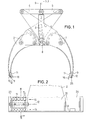
- the gripping device for pipes shown in FIG. 1 has two gripping arms 1 and 2 which intersect like scissors and which are pivoted to one another about the axis 3. At the upper ends of the gripper arms 1 and 2, tabs 4 and 5 are articulated, which are articulated to an eyelet 6. The eyelet 6 is used to hang the gripping device on Rope or chain hangers. Between the joint that connects the two brackets 4 and 5 and the pivot axis 3 of the gripping arms 1 and 2, a tension spring (not shown) is arranged on the one hand and on the other hand a locking device 7 which holds the two gripping arms 1 and 2 in the open position after a tube has been set down, until the gripping device with the adjustable stop 8 is placed on a new pipe to be picked up.
- a tension spring (not shown) is arranged on the one hand and on the other hand a locking device 7 which holds the two gripping arms 1 and 2 in the open position after a tube has been set down, until the gripping device with the adjustable stop 8 is placed on a new pipe to be
- gripping rails 9 and 10 are arranged, which run parallel to the pivot axis 3.
- the gripping rails 9 and 10 are formed by U-profiles.
- a gripping jaw 11 is arranged, which is fastened by a relatively small angle about an axis 12 running parallel to the swiveling axis 3 of the gripping arms 1 and 2.
- the gripping jaws 11 are held by springs in a position approximately corresponding to the gripping position. In this position, the mutually facing surfaces of the opposing gripping jaws 11 diverge from bottom to top.
- Downwardly projecting stops 16 are arranged on the gripping jaws 11 as deflectors.
- the outwardly resilient stop 16 has the effect that the gripping device slides over a pipe without difficulty, although when the gripping device is lowered the two gripping rails are not aligned parallel to the pipe to be received.
- the provided on the male pipe ends anschla g stops 16 bring the two parallel overlapping rails 9 and 10 automatically to a position where they extend in parallel to the axis of the male pipe.
- the stops 16 also prevent the gripping teeth of the gripping jaws from being excessively worn.
- the gripping jaws 11 are pivotally mounted in walls 27 which are welded into the gripping rails 9, 10 at right angles to the pivot axis 3 of the gripping jaws 1, 2.
- the free edges of the flanges of the gripping rails 9, 10 formed from a U-profile serve as lower stops 13 and upper stops 24 of the gripping jaws 11.
- the gripping jaws 11 are equipped with gripping elements 14, 15, which are each composed of a series of gripping teeth 17 which are incorporated into the gripping jaw 11.
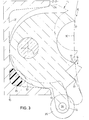
- Fig. 3 shows a view along the section line III-III in Fig. 2, but in which the gripping jaw 11 with its gripping elements 14, 15 abuts the dash-dotted wall 30 of a pipe to be received and the gripping jaw 11 is pivoted slightly downward.
- the gripping jaw 11 is under the action of a rubber-elastic, resilient, strand-like body 25 which is arranged between an abutment surface 31 and the curved rear side 32 of the gripping jaw 11 and extends over the width of the gripping jaw 11.
- the radius of curvature of the curvature of the rear side 32 is approximately twice as large as the distance between the pivot axis 12 and the abutment surface 31.
- the starting position of the gripping jaw 11 and of the rubber-elastic body 25 is also shown in broken lines. In this unloaded position, the gripping jaw 11 is pressed by the resilient body 25 against the upper stop 24.
- the cross section of the resilient body 25 is round.
- This rubber body 25 is - as shown in dash-dotted lines - used with bias so that it is in the lower angle between the web and the lower flange of the U-shaped rail 10.
- the elastic body 25 is carried along by the curved rear side 32 of the gripping jaw 11 and squeezed into the narrowing gap between the rear side 32 and the abutment surface 31.
- the gripping jaw 11 has between the gripping teeth 17 of the upper gripping area 14 and the lower gripping area 15 a semi-cylindrical recess 36 into which an insert 37 made of rubber-elastic material, e.g. Rubber, can be used and fastened by means of screws 38.
- the gripping jaws 11 of the pipe gripper are equipped with these inserts 37 when pipes with a smooth surface are to be gripped.
- the insert 37 has an essentially planar lower gripping area 14 and an upper gripping area 15, which lies against the tube wall.
- the planes of these gripping areas 14 and 15 are at an angle of, for example, 170 ° or 180 ° to one another.
- the semi-cylindrical recess 36 is arranged in such a way that the tooth tips of the gripping teeth 17 are created with its help.
- each gripping jaw 11 is subdivided into at least one plane perpendicular to the pivot axis 12. If a gripper jaw 11 is subdivided into two or three, then two or three elements can be pivoted independently about the axis 12, which elements can also properly fit against a pipe to be gripped if the pipe wall is inclined to the swivel axis 12 of the gripper jaw parts. When picking up a pipe that is inclined or inclined, the gripper jaw parts compress the strand-like, rubber-elastic body 25 to different degrees.
- the pivot axis 12 is considerably smaller in diameter, for example 10-30%, than the bore 40 in the gripping jaw 11 surrounding the pivot axis 12.
- the bore 40 is arranged in this way, and the play between the pivot axis 12 and the bore 40 is so large that the gripping jaw 11 is supported with the curved rear side 32 against the abutment surface 31 and at the same time against the lower flange of the U-rail 10 when the gripping jaw 11 is loaded.
- the gripping jaw 13 In the unloaded state, the gripping jaw 13, as shown, is pressed obliquely upwards against the pivot axis 12 by the prestressed, resilient body 25.
- the gripping surface of the elastic insert 37 for forming the lower gripping area 14 and the upper gripping area 15 is composed of two planes inclined at a relatively small angle to one another.
- the gripping surface of the elastic insert 37 can, however, also be flat overall, because when a pipe is gripped, the curved outer surface of which is pressed into an initially flat gripping surface of the elastic insert 37.
- the rubber is Elastic body 25 between the lower corner of the U-shaped gripping rail 10 and the curved rear 32 of the gripping jaw 11 is arranged.
- a second rubber-elastic body 25 in the upper corner of the U-shaped gripping rail 10.
- the gripping device described has the advantage that it can be assembled very easily and quickly. It is only necessary to pull out the pivot axis 12 in order to replace the gripping jaw 11 and its resilient body 25. Because the curved surface 32 rolls off the prestressed, strand-like elastic body 25 without sliding movement, the gripping jaw 11 is always returned to the same starting position by the resilient body 25.
Landscapes
- Engineering & Computer Science (AREA)
- Mechanical Engineering (AREA)
- Load-Engaging Elements For Cranes (AREA)
- Manipulator (AREA)
- Tyre Moulding (AREA)
Priority Applications (1)
| Application Number | Priority Date | Filing Date | Title |
|---|---|---|---|
| AT81102717T ATE13656T1 (de) | 1980-04-12 | 1981-04-10 | Greifvorrichtung fuer rohre. |
Applications Claiming Priority (2)
| Application Number | Priority Date | Filing Date | Title |
|---|---|---|---|
| DE3014146 | 1980-04-12 | ||
| DE19803014146 DE3014146A1 (de) | 1980-04-12 | 1980-04-12 | Greifvorrichtung fuer rohre |
Publications (3)
| Publication Number | Publication Date |
|---|---|
| EP0038037A2 true EP0038037A2 (fr) | 1981-10-21 |
| EP0038037A3 EP0038037A3 (en) | 1982-01-13 |
| EP0038037B1 EP0038037B1 (fr) | 1985-06-05 |
Family
ID=6099877
Family Applications (1)
| Application Number | Title | Priority Date | Filing Date |
|---|---|---|---|
| EP81102717A Expired EP0038037B1 (fr) | 1980-04-12 | 1981-04-10 | Dispositif de préhension pour tuyaux |
Country Status (3)
| Country | Link |
|---|---|
| EP (1) | EP0038037B1 (fr) |
| AT (1) | ATE13656T1 (fr) |
| DE (2) | DE3014146A1 (fr) |
Cited By (4)
| Publication number | Priority date | Publication date | Assignee | Title |
|---|---|---|---|---|
| JPS58144577U (ja) * | 1982-03-19 | 1983-09-29 | 新和機械工業株式会社 | 管掴み機 |
| GB2175038A (en) * | 1985-02-27 | 1986-11-19 | Drg Uk Ltd | Coupling means |
| GB2211170B (en) * | 1987-12-15 | 1992-05-13 | Amada Co Ltd | Jaw exchange device for a plate bending machine and a robotic device equipped with said jaw exchange device and a manipulator. |
| US7065088B2 (en) | 1998-01-19 | 2006-06-20 | Juniper Networks, Inc. | Asynchronous transfer mode switch with function for assigning queue having forwarding rate close to declared rate |
Family Cites Families (13)
| Publication number | Priority date | Publication date | Assignee | Title |
|---|---|---|---|---|
| US2927704A (en) * | 1960-03-08 | Hydraulic device | ||
| GB100550A (en) * | 1911-05-24 | 1916-06-08 | Saint Gobain | Improvements in Gripping Appliances Suitable for Lifting Cylindrical Articles. |
| FR433383A (fr) * | 1911-08-18 | 1912-01-05 | The Yale & Towne Manufacturing C | Perfectionnements apportés aux grappins |
| FR552139A (fr) * | 1921-10-04 | 1923-04-24 | Mâchoires pour pince à serrage automatique | |
| US2497600A (en) * | 1945-05-21 | 1950-02-14 | William M Grigsby | Hoist device |
| DE1117280B (de) * | 1959-02-05 | 1961-11-16 | Peter Moskopf | Vielfachgreifer zum Stapeln, Arken und Verladen von Deckensteinen, Platten od. dgl. |
| FR1218128A (fr) * | 1959-02-28 | 1960-05-09 | Pince à galets | |
| US3061357A (en) * | 1959-06-05 | 1962-10-30 | Nat Steel Corp | Lifting apparatus |
| DE1921959B2 (de) * | 1969-04-30 | 1974-04-18 | Fried. Krupp Gmbh, 4300 Essen | Traversen-Geschirr zum Transport von Brammen oder dergl |
| DE1937281A1 (de) * | 1969-07-23 | 1971-02-04 | Hermann Steinweg Kg Baumaschin | Einseitig wirkender Krangreifer fuer Steinpakete des Bauwesens |
| DE2722689C2 (de) * | 1977-05-18 | 1983-02-03 | Alfred Ing.(grad.) 8160 Miesbach Kinshofer | Auf eine Greifzange unrüstbarer Zweischalengreifer |
| DE2901808A1 (de) * | 1979-01-18 | 1980-07-31 | Oldenburger Betonsteinwerke | Greifer zum lagenweisen verlegen von zu scheibenfoermigen verlegeeinheiten zusammengefassten pflastersteinen |
| DE2936990A1 (de) * | 1979-09-13 | 1981-04-02 | Josef Ing.(grad.) 5142 Hückelhoven Emunds | Greifvorrichtung fuer rohre |
-
1980
- 1980-04-12 DE DE19803014146 patent/DE3014146A1/de not_active Withdrawn
-
1981
- 1981-04-10 AT AT81102717T patent/ATE13656T1/de not_active IP Right Cessation
- 1981-04-10 EP EP81102717A patent/EP0038037B1/fr not_active Expired
- 1981-04-10 DE DE8181102717T patent/DE3170815D1/de not_active Expired
Cited By (5)
| Publication number | Priority date | Publication date | Assignee | Title |
|---|---|---|---|---|
| JPS58144577U (ja) * | 1982-03-19 | 1983-09-29 | 新和機械工業株式会社 | 管掴み機 |
| GB2175038A (en) * | 1985-02-27 | 1986-11-19 | Drg Uk Ltd | Coupling means |
| GB2211170B (en) * | 1987-12-15 | 1992-05-13 | Amada Co Ltd | Jaw exchange device for a plate bending machine and a robotic device equipped with said jaw exchange device and a manipulator. |
| US7065088B2 (en) | 1998-01-19 | 2006-06-20 | Juniper Networks, Inc. | Asynchronous transfer mode switch with function for assigning queue having forwarding rate close to declared rate |
| US7391726B2 (en) | 1998-01-19 | 2008-06-24 | Juniper Networks, Inc. | Switch with function for assigning queue based on forwarding rate |
Also Published As
| Publication number | Publication date |
|---|---|
| DE3014146A1 (de) | 1981-10-15 |
| EP0038037A3 (en) | 1982-01-13 |
| ATE13656T1 (de) | 1985-06-15 |
| EP0038037B1 (fr) | 1985-06-05 |
| DE3170815D1 (en) | 1985-07-11 |
Similar Documents
| Publication | Publication Date | Title |
|---|---|---|
| DE2319736B2 (de) | Abstreifvorrichtung für Gurtbänder | |
| CH648223A5 (de) | Vorrichtung zum ueberfuehren von abgelaengten draehten aus einem losen drahtbuendel in eine einfachlage von parallelen draehten. | |
| DE2059143A1 (de) | Kontinuierlich veraenderbare Flaeche | |
| DE1809568A1 (de) | Sicherheitsvorrichtung fuer Hub-Greifzangen | |
| DE19628140C1 (de) | Vorrichtung zum Ergreifen von Behältern | |
| EP0038037B1 (fr) | Dispositif de préhension pour tuyaux | |
| EP3293841B1 (fr) | Armature battante de sécurisation des câbles conducteurs | |
| DE4400495A1 (de) | Vorrichtung zum Ergreifen, Transportieren und Palettieren von Gegenständen | |
| WO1981000705A1 (fr) | Grappin de conduite | |
| DE4237776C2 (de) | Kette zum Übertragen von Bewegungen und/oder Kräften | |
| EP2698474A1 (fr) | Dispositif de pose de pavés avec un dispositif de support de mâchoires de préhension | |
| DE8010062U1 (de) | Greifvorrichtung fuer rohre | |
| DE2817591C2 (de) | Vorrichtung zum Aufhängen und Transportieren von Stangenmaterial, das einer Tauchbadbehandlung unterzogen werden soll | |
| DE2018991A1 (de) | Greifzange zum Erfassen von runden Stangen | |
| DE69704493T2 (de) | Positionierungsvorrichtung | |
| DE3151772C2 (de) | Hubtraverse mit Saugkörpern | |
| DE2936990A1 (de) | Greifvorrichtung fuer rohre | |
| DE2746066C2 (de) | Kettenstoppvorrichtung | |
| DE1921959B2 (de) | Traversen-Geschirr zum Transport von Brammen oder dergl | |
| EP0270488A2 (fr) | Raclette pour appareil à rouler la pâte | |
| CH617119A5 (en) | Apparatus for cutting boards to size | |
| DE102005048836A1 (de) | Durchlaufregal zur Kommissionierung von Lagereinheiten | |
| EP0845067A1 (fr) | Charpente porteuse pour surfaces de toit ou de paroi | |
| DE2642029C3 (de) | Klemmklaue für eine Verspannvorrichtung zum Abspannen von dem Einbau von Streckenausbauelementen dienenden, in der Strecke verfahrbaren Geräten | |
| DE2042898A1 (de) | Reifengleitschutzkette |
Legal Events
| Date | Code | Title | Description |
|---|---|---|---|
| PUAI | Public reference made under article 153(3) epc to a published international application that has entered the european phase |
Free format text: ORIGINAL CODE: 0009012 |
|
| AK | Designated contracting states |
Designated state(s): AT BE CH DE FR GB IT LU NL SE |
|
| PUAL | Search report despatched |
Free format text: ORIGINAL CODE: 0009013 |
|
| AK | Designated contracting states |
Designated state(s): AT BE CH DE FR GB IT LU NL SE |
|
| RAP1 | Party data changed (applicant data changed or rights of an application transferred) |
Owner name: EMUNDS, JOSEF |
|
| 17P | Request for examination filed |
Effective date: 19820710 |
|
| GRAA | (expected) grant |
Free format text: ORIGINAL CODE: 0009210 |
|
| AK | Designated contracting states |
Designated state(s): AT BE CH DE FR GB IT LI LU NL SE |
|
| PG25 | Lapsed in a contracting state [announced via postgrant information from national office to epo] |
Ref country code: SE Free format text: THE PATENT HAS BEEN ANNULLED BY A DECISION OF A NATIONAL AUTHORITY Effective date: 19850605 Ref country code: NL Effective date: 19850605 Ref country code: IT Free format text: LAPSE BECAUSE OF FAILURE TO SUBMIT A TRANSLATION OF THE DESCRIPTION OR TO PAY THE FEE WITHIN THE PRESCRIBED TIME-LIMIT;WARNING: LAPSES OF ITALIAN PATENTS WITH EFFECTIVE DATE BEFORE 2007 MAY HAVE OCCURRED AT ANY TIME BEFORE 2007. THE CORRECT EFFECTIVE DATE MAY BE DIFFERENT FROM THE ONE RECORDED. Effective date: 19850605 Ref country code: BE Effective date: 19850605 |
|
| REF | Corresponds to: |
Ref document number: 13656 Country of ref document: AT Date of ref document: 19850615 Kind code of ref document: T |
|
| REF | Corresponds to: |
Ref document number: 3170815 Country of ref document: DE Date of ref document: 19850711 |
|
| ET | Fr: translation filed | ||
| NLV1 | Nl: lapsed or annulled due to failure to fulfill the requirements of art. 29p and 29m of the patents act | ||
| PG25 | Lapsed in a contracting state [announced via postgrant information from national office to epo] |
Ref country code: DE Effective date: 19860101 |
|
| PLBE | No opposition filed within time limit |
Free format text: ORIGINAL CODE: 0009261 |
|
| STAA | Information on the status of an ep patent application or granted ep patent |
Free format text: STATUS: NO OPPOSITION FILED WITHIN TIME LIMIT |
|
| PG25 | Lapsed in a contracting state [announced via postgrant information from national office to epo] |
Ref country code: AT Effective date: 19860410 |
|
| PG25 | Lapsed in a contracting state [announced via postgrant information from national office to epo] |
Ref country code: LU Free format text: LAPSE BECAUSE OF NON-PAYMENT OF DUE FEES Effective date: 19860430 Ref country code: LI Effective date: 19860430 Ref country code: CH Effective date: 19860430 |
|
| 26N | No opposition filed | ||
| GBPC | Gb: european patent ceased through non-payment of renewal fee | ||
| PG25 | Lapsed in a contracting state [announced via postgrant information from national office to epo] |
Ref country code: FR Free format text: LAPSE BECAUSE OF NON-PAYMENT OF DUE FEES Effective date: 19861231 |
|
| REG | Reference to a national code |
Ref country code: CH Ref legal event code: PL |
|
| REG | Reference to a national code |
Ref country code: FR Ref legal event code: ST |
|
| PG25 | Lapsed in a contracting state [announced via postgrant information from national office to epo] |
Ref country code: GB Effective date: 19881118 |