EP0038048A2 - Lichtabtastanordnung für elektrophotographisches Druckplattenherstellungsgerät - Google Patents
Lichtabtastanordnung für elektrophotographisches Druckplattenherstellungsgerät Download PDFInfo
- Publication number
- EP0038048A2 EP0038048A2 EP81102774A EP81102774A EP0038048A2 EP 0038048 A2 EP0038048 A2 EP 0038048A2 EP 81102774 A EP81102774 A EP 81102774A EP 81102774 A EP81102774 A EP 81102774A EP 0038048 A2 EP0038048 A2 EP 0038048A2
- Authority
- EP
- European Patent Office
- Prior art keywords
- copyboard
- carriage
- pattern
- lamp
- illuminating
- Prior art date
- Legal status (The legal status is an assumption and is not a legal conclusion. Google has not performed a legal analysis and makes no representation as to the accuracy of the status listed.)
- Withdrawn
Links
Images


Classifications
-
- G—PHYSICS
- G03—PHOTOGRAPHY; CINEMATOGRAPHY; ANALOGOUS TECHNIQUES USING WAVES OTHER THAN OPTICAL WAVES; ELECTROGRAPHY; HOLOGRAPHY
- G03G—ELECTROGRAPHY; ELECTROPHOTOGRAPHY; MAGNETOGRAPHY
- G03G15/00—Apparatus for electrographic processes using a charge pattern
- G03G15/04—Apparatus for electrographic processes using a charge pattern for exposing, i.e. imagewise exposure by optically projecting the original image on a photoconductive recording material
Definitions
- the invention herein is directed to an improved light scanning assembly for use in the manufacture of printing plates, particularly for lithographic use, by high speed electrostatic methods.
- the plates produced by the apparatus and method of the invention are superior to printing plates made by known methods whether photographically or electrostatically.
- Lithographic printing plates made by the conventional photographic methods are expensive and complex; plates made by electrostatic methods which are known have never been widely used because they require considerable time to produce, have very little life and are low in resolution and spectral response. The latter two disadvantages are characteristic also of photographically made lithographic plates.
- Lithographic printing is a process which is basically very old and well-known. For many years, even well into this century, the technique was practiced on special stone surfaces. A greasy image was applied to a surface, the non-imaged portions being rendered hydrophilic (water attractive, oil repellent). The imaged parts being hydrophobic (water repellent, oil attractive) when a paper receptor is pressed against the surface which has been wetted with water and the greasy ink, the greasy ink having adhered only to the image will be transferred to the paper.
- Offset lithography is probably the most important method of printing today.
- the principle is that ink is offset first from the plate to a rubber blanket and then from the blanket to the paper receptor. There may be an intervening metal drum instead of a rubber blanket.
- the printing image is rendered hydrophobic, i.e., repellent to water but also attractive to grease.
- the non-printing areas are rendered just the opposite, that is, hydrophilic.
- the plate On the press the plate is mounted on a plate cylinder which, as it rotates, comes into contact successively with rollers wet by a water or dampening solution and rollers wet by grease-based ink.
- the dampening solution wets the non-printing areas of the plate and prevents the ink from wetting these areas.
- the ink wets the image areas which are transferred to the intermediate blanket cylinder.
- the paper picks up the image as it passes between the blanket cylinder and the impression cylinder.
- Ink receptivity is accomplished by using inherently oleophilic (having an affinity for oil) resins or metals like copper or brass on the image areas.
- Water receptivity of the non-image areas is usually achieved by using hydrophilic metals like chromium, aluminum or stainless steel and this receptivity is maintained in platemaking and storage by using natural and synthetic gums such as for example, gum arabic.
- All offset printing plates which are used for long runs exceeding several thousands of impressions are made by indirect imaging methods.
- the copy or intelligence is first required to be photographed onto silver halide film and the film negative then used to transfer the image to the printing plate.
- the transfer is accomplished in all such cases by means of photographic projection onto a coating which is light sensitive and carried by the plate.
- the negative is used to project the image onto the plate and the processes which follow for the development of the image on the plate vary.
- the plates are required to be stored in darkness until used or the light-sensitive coating applied just before use. This is true of the three types of long-run offset plates which are most popularly used today.
- the three types of long run plates which are known at this time are surface, deep etch and bimetal.
- the surface plates are those in which a light-sensitive coating is exposed to a negative, developed etc. The process of achieving the plate requires many steps and treatments. On deep etch plates, after exposure to the negative, the coating in the image areas is removed and coppered chemically lacquered and inked so they are ink receptive. The plate is usually aluminum and the process is quite involved and requires considerable skill.
- Bimetal plates are similar to deep etch in that the light sensitive coating is removed from the image areas but these areas consist of copper or brass.
- a copyboard was mounted horizontally at the top of a light tight enclosure at convenient location to receive a copy original thereon.
- the copyboard was translated swingably to a substantially vertical disposition where it was scanned progressively by a fixed lamp assembly from its face and/or its rear if the copy original is transparent.
- the scanning assembly was formed of a front reflector, parabolic in configuration and extending fully across the front of the copyboard.
- a tubular lamp faced the pattern when same was oriented vertically.
- a rear reflector similar to the front reflector also extended fully across the rear of the copyboard and was provided with its own tubular lamp when same is at its vertical disposition.
- the reflectors and lamps are assembled mounted between plates or brackets located outside of the support standards provided but quite close thereto.
- the brackets were coupled to an endless chain driven by a drive motor synchronously operated with the drive motor for the carriage so as to move the light scanning assembly up or down illuminating the copyboard progressively along a band across the front and rear face thereof, depending upon whether one or the other of the lamps are energized.
- An optical train was arranged to view the whole field of the copyboard and hence, the subject matter of the original was projected onto a charged electrophotographic member by way of a slit that moves over the sensitive surface of the electrophotographic member in synchronism with the scanning of the original.
- the electrophotographic member comprised a flexible article based upon a polyester substrate that is transparent or upon a substrate comprising sheet metal that is not as flexible and opaque, the surface of the elctrophoto g raphic member that is exposed to the sweeping light beam comprising in each case a sputtered coating of a wholly inorganic photoconductor that has a crystalline structure and is capable of being rapidly charged, imaged and toned as taught in U.S. Patent 4,025,339.
- the electrophotographic member of Serial No. 10,497 was carried on a hinged platen which was located at the top of the enclosure but spaced from the "home" position of the copybord.
- the hinging arrangement enabled the user to mount the electrophotographic member horizontally in ambient light and then to rotate the member 180 degrees into an aperture in the enclosure while simultaneously closing the aperture, the photosensitive coating side facing into the enclosure.
- the slit was provided in a carriage which carried a charging device, said slit, a toning device and excess toner removal means, all moving together with the carriage across the photosensitive surface of the electrophotographic member in synchronism with the light scanning assembly.
- the invention herein relates to improvements in the light scanning assembly which increase the versatility of the plate making apparatus disclosed in said referenced application Serial No. 10,497, which increases lamp life by enabling improved cooling of the lamps, which provides increased light concentration along a narrow band of the copyboard for improved reproduction of the pattern and reduces light losses by employing focused light beams.
- the invention herein provides a light scanning assembly comprising a fixed lamp pair sub-assembly and a pivotal single lamp assembly mounted on respective bracket supports to illuminate a selected one of the front and rear faces of the copyboard herein above described as during translation of said assembly across the pattern of the original carried by said copyboard when the copyboard is disposed in vertical orientation while the aformentioned processing carriage synchronously is translated across the electrophotographic member.
- the fixed lamp pair is arranged spaced and aligned one above the other, each having an elliptically configured reflector associated therewith for focusing the emitted light to a common band across the width of said copyboard from whence it is viewed by the field of the optical train of said apparatus.
- the single lamp is mounted across the rear face of the copyboard and is energized when the original carried thereby is transparent.
- This single lamp is associated also with an elliptically configured reflector for developing a focused beam directed to and through the copyboard along a line intersecting the center line of the optical lens arrangement comprising the optical train.
- Bracket means mounting said single lamp and reflector is itself mounted for pivotal rotational movement to the bracket carrying the fixed lamp pair and is pivoted along a predefined arc during translation of the lamps and reflectors across the pattern of the original carried by said copyboard whereby the directed beam continuously follows a straight line always intersecting the center line of the optical lens arrangement at the same location.
- the invention there will be described as a light scanning or illuminating assembly for electrophotographic imaging apparatus for making graphic printing plates.
- An articulated copyboard is mounted between a pair of like upright support assemblies for translation between a horizontally oriented loading condition and a vertically oriented imaging or scanning condition such as discussed in the referenced application, Serial No. 10,497.
- a single uninterrupted track is defined as a continuous groove formed within said support assemblies and a chain drive is accomodated therein.
- Pins means are secured to said copyboard and are carried by said chain drive, to translate the copyboard from the horizontally oriented loading condition along a first path with its surface horizontal and then along a second path rotated 90 degrees from the first path.
- a light scanning assembly is provided for scanning movement across the front or rear face of the copyboard illuminating same progressively when the copyboard is oriented vertically.
- a first or fixed pair of illumination lamps are mounted on a translatable carriage or bracket to direct a common beam of light along a path about one and one-half inches across the facing copyboard, the fixed pair being capable translation fully across the said face synchronously with the processing carriage of said imaging apparatus.
- the entire front face of the copyboard is viewed by the optical system and the projected image of the pattern directed to the undersurface of a charged electrophotographic member via the slit carried by the carriage.
- a second lamp is positioned facing the rear of the copyboard. This lamp with its associated reflector, is carried on a pivotable bracket.
- the lamp pair are arranged one above the other spaced apart and aligned, including reflectors for each of elliptical configuration, the light from said lamps being directed in a focused beam to illuminate a narrow band across the facing copyboard, an additional lamp and its associated elliptically configured reflector carried on a pivotally mounted bracket for movement through a predefined arc so that the light path is defined along a straight line beam always focused at the optical center of the optical train during full scanning function of the single lamp.
- Cam means in the form of a wheel are described secured to the single-lamp bracket acting to follow a canted track formed on said support assembly.
- the apparatus in which the light scanning assembly of the invention advantageously is employed may be considered a camera or projector combined with an electrostatic plate making processor.
- the camera is invested with the task of responding to the light which is produced by the light scanning system which illuminates a copyboard upon which there has been placed or secured a variegated pattern (original) which it is desired to project onto a surface.
- the pattern may comprise a single ember or multiple members in the form of photographs, drawings, diagrams, text, captions, headings, numerical columns or the like.
- Opaque, translucent or transparent articles or members are included. These may be clamped between a pair of glass plates into a pair of hinged frames and comprising the copyboard. The plates may be clamped at their entry edges with the frame being provided with registration pins for locating the member thereon.
- the copyboard is disposed at one end of the apparatus and is available in a horizontal position when the cover is open. After the pattern carrying member has been inserted between the glass plates, the copyboard is driven from its horizontal position adjacent the top of the apparatus to a vertical position down inside of the apparatus, with the pattern facing the lens system which is provided in the center of the apparatus.
- the operator may move to the opposite end of the apparatus to position and to mount the plate which is to be made carrying the pattern of the material that is carried on the copyboard.
- the apparatus has a platen at the end opposite the copyboard which is mounted on the bottom of a hinged cover member.
- the cover member When the cover member is swung open, it exposes the platen which is provided means for holding the plate securely with the photoconductive coating thereof facing outwardly.
- the cover member When the cover member is swung to a closed position it closes off the upperpart of the apparatus near its end.
- the optical train including a lens system, is mounted on a partition generally centrally located between the platen end of the apparatus and the copyboard end of the apparatus.
- the plate which is being made, is formed on a rectangular member of electrophotographic material which may be based upon metal or plastic film such as polyester.
- the operator swings the platen cover open end places the electrophotographic member on the platen.
- Registration pins may be provided on the platen to assure proper and repeatable orientation and positioning of the member on said platen.
- the platen When a metal member is employed, the platen may be provided with magnetic means as a part thereof to hold the member securely with the photoconductive coating thereof exposed.
- the cover member is swung to a closed condition causing the photoconductive surface coating of the electrophotographic member to face downward.
- the copyboard is arranged vertically and the photoconductive coating surface is arranged horizontally.
- the light scanning assembly includes a lamp carriage including a mounting for fixedly holding a pair of illuminating lamps and their associated elliptical reflectors on the facing side of the copyboard,.and a second, pivotally mounted, lamp and its associated reflector, on the rear side thereof.
- the light scanning assembly is driven mechanically along a generally vertical path to scan the copyboard and hence the pattern on its surface from the bottom to the top.
- the illuminated pattern is viewed as a moving strip or horizontal band by the optical train, the area of the facing copyboard being within the field thereof.
- the resulting image is projected through the optical train to a pit or chamber whose upper end is closed off by the platen.
- a diagonal mirror in the wall of the chamber opposite the optical train and below the platen diverts the image so as to project same upward toward the platen.
- a carriage which is normally in its home position beneath the open position of the platen.
- This carriage includes at its leading edge a high voltage corona device in the form of wires stretching across the width of the carriage normal to the direction of its movement.
- these wires are reciprocated, while energized, according to the teachings of U.S. Patent No. 4,076,406.
- a slit which is open through the carriage and which exposes a strip of the photoconductive coating surface of the electrophotographic member as the carriage moves.
- a wide metal plate which provides a toning bias, and which carries a flowing layer of liquid toner supplied by a sump beneath the plate and brought up to-the plate by a roller that is immersed in the sump.
- a roller Following the roller, there is a slot opening to a vacuum nozzle which sucks excess toner from the toned image on the photoconductive coating surface.
- An elongate space is defined between the roller and the wall of the toner sump to catch runoff of excess toner. Air under pressure can be expelled against the toned coating surface to drive excess dripping toner into the vacuum slot for drying the toned image.
- the carriage and the light scanning assembly move simultaneously synchronously, the light scanning assembly moving from the bottom of the vertically arranged copyboard to its top end and illuminating a-narrow band across the pattern progressively simultaneously with the movement of the carriage along the length of the electrophotographic member.
- the platen cover is now opened, the plate examined and if satisfactory, is removed. It will be fairly dry even without having been subjected to fixing or fusing. This is because of the stream of air flowing from the nozzle.
- the apparatus is capable of carrying a fusing or fixing device on the carriage or having one located at the end of the forward stroke of the carriage, but it is preferred that the fixing not be complete so that the plate can be corrected by the operator if he desires before fixing.
- the operator may leave the copyboard in position vertically if he desires to make another plate of the same pattern or he can throw a switch to bring the copyboard back to its upper horizontal position so that another pattern can be applied thereto after the one in place is removed or modified.
- the copyhoard is a part of a module which is movable along a single continuous track provided on the supporting frame or chassis defining the enclosure of the apparatus whereby properly to focus the projected image upon the plate.
- the module is self- contained in that it includes the copyhoard, the guide reans for movement of the copyboard between its horizontal and vertical positions, the drive motor and belts for moving the copyboard, the entire light scanner assembly of the invention with its associated guides and driving motor and drive and means for connecting the module into the entire system such as plugs, connectors and the like.
- suitable means are provided to clamp the module to the rails of the framework of the apparatus.
- FIG. 1 apparatus 10 is shown in a condition with the copyboard cover 22 closed and the platen cover 24 half way open.
- the platemaker apparatus 20 is formed of a bottom pedestal 26 upon which is mounted the main chassis or framework 28.
- the main chassis is illustrated as a relatively elongate enclosure whose exterior may be ornamental and comprised of panels such as the end panel 30 and the front panel 32.
- the interior framework will however be formed or robust steel members suitably welded or bolted together to provide a rigid and stable platform for the apparatus 10, considering, of course, that there is included an effective camera with a long focal length and that sharp reproductions of the patterns are desired.
- the upper part of the main chassis 28 has a sub-chassis mounted thereon, the sub-chassis being designated generally as 34 in Figure 1.
- the sub-chassis 34 includes rails and tracks which are provided for several purposes. Typically, there is a plurality of brackets welded to structural members 37 and having structural rails of the sub-chassis 34 bolted thereto by means of shock mountings (not shown) which may include elastomeric bushings.
- the structural rails include interior track 42 upon which the copyboard module 60 may be moved and secured.
- an instrument and control panel 48 ( Figure 1) which includes a housing for the gauges and switches required to control and operate the apparatus 10.
- a central partition or generally vertical wall 50 which extends downward from the chamber 46 toward the bottom floor 52 of the chassis 28, this partition 50 serving as one wall of the projection chamber 54.
- the wall 50 also separates the copyboard end of the interior of the device from the projection chamber 54, such end being generally referred to as the copyboard projection chamber 56.
- the copyboard 58 is disposed in the copyboard chamber 56 and it generally is associated with the copyboard module 60.
- the copyboard module is in the form of an independent article that can be manufactured separately from the remainder of the apparatus 10 and then incorporated therein. It should be understood that the copyboard 58 need not he incorporated in a module but could be constructed to operate as a permanently connected portion of apparatus 10.
- the copyhoard module 60 is mounted for movement along continuous track 42 and adjusted for proper focus after which it is clamped in place by suitable damns (not shewn).
- the central partition or wall 50 serves to support the optical train including lens system 64 by means of which the pattern on the copyboard 58 is projected to the projection chamber 54.
- the chamber 54 has a back wall 66 which is arranged at a 45° angle relative to the vertical so that the rays indicated at 68 which originate at the illuminated copyboard 58 will be directed via lens system 64 to a mirror 70 mounted on the interior of said inclined wall 66 and diverted upward to the slit in the carriage 72.
- the processing carriage 72 is translatable in a predetermined path for the purpose of imaging the electrophotographic member 74 which is mounted on the platen 76.
- the platen 24 is hinged at 78 so that it can be swung from a position in which it is folded back upon the top panel portion 80 of the sub-chassis 34 (see the arcuate broken lines of Figure 1).
- the copyboard chamber is normally closed off by the cover 22, that also swings as indicated by the broken lines of Figure 1.
- the carriage 72 moves from its home position in a suitable enclosed chamber 82 upon guides 84 which are mounted to the tracks 42 from its home chamber 82, out over the projection chamber 54 and into the terminal position chamber 46.
- the carriage 72 is connected to various devices which are mounted in the enclosure of the chassis 28, for the most part disposed on the base 52.
- flexible hoses 86 connecting to the vacuum and air pressure devices 87 and the toner circulating pipes 38. These may be separate or within one another.
- Flexible wires connect to sources of power (not shown) located in the body of the apparatus.
- the carriage 72 is driven hy belts 90 Which engage over sheaves 284, 286 that are in turn rotated by connection with a motor 92 mounted in the chassis 28.
- the belts are clamped to the carriage 72.
- the principal effect of movement of the carriage 72 is to sweep a slit over photoconductive coating on the face of the electrophotographic member 74.
- This slit is supplied with illumination derived from the pattern mounted on the copyboard 58.
- the copyboard 58 synchronously is strongly illuminated by the lamps of the light scanning assembly provided by this invention, said assembly being translated upward while the carriage is moving from the chamber 82 to the chamber 46.
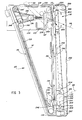
- the copyboard module 60 is constructed as a generally triangular metal frame 96 which fits upon the tracks 42 and can slide thereon for installation. Clamps (not shown) engage the bottom of the tracks 42 to secure the frame in place when the desired location is reached.
- the frame 96 has a pair of vertically arranged portions 98 which, with horizontal portion 100 and inclined frame 97 form frame 96.
- a brace 102 is connected between side plates 104 and a bottom connecting member 106 connects the bottom ends of standard portions 98 to define a base.
- Each triangular frame 96 is provided with a continuous guide groove 108"that extends along the length of the horizontal member 100 ; the vertical member 98 and the inclined frame member 97.
- the groove 108 opens inwardly and is curvilinear around the corners 110.
- the groove 108 has a generally portion 112, the curved portion 110 and a vertical portion 114 formed in member 98.
- the copyboard 58 comprises a pair of transparent rectangular glass plates 116,118, each set into a metal frame 120 which is hingedly coupled along one edge and clamped at 124.
- the pattern is formed by the materials which may be adhered to the glass and/or clamped in place by clamping the frames 120 carrying glass plates 116,118 together.
- Bridging shaft 132 carries roller bearing sprockets 134,134' at opposite ends, the pair located close to one end of the edge of copyboard 58.
- a spring biased movable sprocket wheel 136 is provided for applying suitable tension to the sprocket chain 138 mounted on sprockets 134',140.
- Sprocket wheel 136 is mounted on plate 104.
- Sprocket chain 152 engages the motor output sprocket wheel 144 and driving sprocket wheel 134' located offset from sprocket wheels 134',140.
- Spring biased bracket 154 is seated in slide 156 and carries tension sprocket 136 to apply sufficient adjustable tension to said chain 138.
- Chain 138 is coupled to the copyboard by suitable trucks or pins carried by the copyboard frame 120.
- the copyboard 58 will move within the module 60.
- the copyboard 58 moves to the vertically oriented position as shown in Figure 2, it is disposed in condition to be scanned by light scanning assembly 20.
- the module 60 also carries the light scanning assembly 20 constructed in accordance with the herein invention and whose purpose is to illuminate the pattern on the copyboard 58 progressively as the carriage 72 moves across the projection chamber 54.
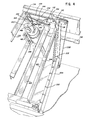
- the light scanning assembly designated herein by reference character 20, includes a pair of front reflectors 202 and 204 of elliptical configuration and extending fully across the front face of the copyboard 58.
- the reflectors 202 and 204 are aligned one with the other in superposed spaced relationship each disposed at an equal but oppositely facing angles relative to the copyboard 58.
- the reflectors 202 and 204 are secured to bridging bars 206 and 208 by clamps 210.
- the bridging bars are in turn secured to brackets 212 at their respective opposite ends.
- the tubular lamps 214 and 216 are mounted in fixed array at a location spaced from the respective reflectors 202 and 204 so that the rays of light emitted therefrom as beams intersecting at a common band across the facing copyboard.
- a suitable shaft is mounted journaled in the brackets 212 at the floor of the enclosure with sprocket wheels 218 secured at the ends thereof.
- Second sprocket wheels 220 are journaled in bracket 222 spaced from sprocket wheels 218.
- a pair of upper sprocket wheels 224 and 226 are mounted on upper brackets 228 aligned with each sprocket wheel set 218,220.
- the brackets and bridging bar define a light scanning carriage and include pin means represented at 230 coupled to an endless sprocket chain 232 threaded about sprocket wheels 218,220 and 224,226.
- a separate drive motor 234 is drivably coupled to one set of sprocket wheels for driving the light scanning assembly up or down.
- the light scanning assembly further includes an additional reflector 236, also of elliptical configuration having associated therewith an illuminating lamp 238.
- a bridging bar 206' mounts the reflector 236 between a pair of pivotable end brackets 242.
- a wheel 244 is coupled fixedly to each bracket 242 and follows an inclined track 246 defined along one edge of canted upright 248.
- Brackets 242 are not spring biased, hence for return to its base condition at the lower end of the vertically oriented copyboard 58, depends only upon their weight to cause such return.
- the brackets 242 are carried with the travel of the sprocket chain 232 and selectively rotate during the progress upward to direct its beam of light to and through the original and copyboard. Because of the pivoting action through a predetermined arc as shown in bottom outline in Figure 4, the beam 68' from lamp 238 and reflector 236 always is focused along a straight line direct to the optical center of the
- connection between lamps 214,216 and 238 to the power supply 250 is taken through vacuum relays 242 to provide additional power to operate the two (fixed) lamp system when the "original" is opaque.
- Larrps having illumination characteristics such as Xenon lamps suitable can be used.
- the lamps are generally open and accessible primarily, for cooling.
- the carriage 72 is an assembly which is made of sheet metal and has several important components. At its front end there is an upwardly opening through ?54 which carries corona wires 256 extending along its length, that is, transverse of the direction of movement of the carriage 72. The carriage 72 moves to the right and left as viewed in Figure 2. The corona wires 256 ray be mounted to a reciprocating support as taught by U.S. Patent 3,978,380. Next along the carriage 72 toward the right is a slit 253 or elongate aperture which opens to the top of the carriage 72, and is intended to sweep across the electrophotographic member or plate 74 as it can be called, in synchronish with the movement of the light scanning assembly 20 in order to expose said plate 74 progressively. It will be seen tnat the entrance to the slit 256 is tapered, the taper being indicated by the walls 258 so that the rays of light reflected from the mirror 70 will be unobstructed in impinging against the plate surface.
- the movement of the carriage carries the toner on the plate 270 close enough to the bottom surface of the electrophotographic member so that toning will take place.
- the plate 270 is spaced from the electrophotographic member 74. Excess toner will be drawn into gap 272 to return to sump 262.
- Adjacent gap 272 is the narrow mouth 274 of a vacuum knife 276 communicating with vacuum nozzle 278 for sucking excess toner from the photoconductive surface of the electrophotographic member 74 while the carriage 72 traverses same.
- the carriage 72 can include side blocks (not shown) that engage upon interior guide rods 34 which are mounted to the tracks 42.
- a suitable drive motor 280 drives the belt 282 extending parallel along the tracks 42 made by socket wheels 284 and 286.
- the carriage 72 is connected by pipes, conduits and wire to the various source of voltage, storage and pumping of toner, air and vacuum, etc.
- the radiant energy distribution projected to the photoconductive coating surface of the electrophotographic member is variable due to losses believed due to lens aberation of the optical system, illumination intensity variations across the copyboard and from side to side of the copyboard.
- the slit can be provided with a mask which has a gradually decreasing width opening from opposite ends, describing a bow-tie like opening.
- a d.c. motor has an output shaft carrying an eccentrically mounted circular wheel.
- a linkage connects the wheel to a control lever operable upon the aperture controlling iris of the optical system.
- the operation of the motor is synchronized with the movement of the light scanning assembly to vary the lens opening between a greater opening (f-9) at the upper and lower positions of the scanning assembly to a smaller opening (f-11) when the scanning assembly is at the center of the copyboard between its extreme positions.
Landscapes
- Physics & Mathematics (AREA)
- General Physics & Mathematics (AREA)
- Exposure Or Original Feeding In Electrophotography (AREA)
- Manufacture Or Reproduction Of Printing Formes (AREA)
- Exposure And Positioning Against Photoresist Photosensitive Materials (AREA)
- Optical Systems Of Projection Type Copiers (AREA)
Applications Claiming Priority (2)
| Application Number | Priority Date | Filing Date | Title |
|---|---|---|---|
| US06/139,465 US4338018A (en) | 1980-04-11 | 1980-04-11 | Light scanning assembly for electrophotographic printing plate making apparatus |
| US139465 | 1980-04-11 |
Publications (2)
| Publication Number | Publication Date |
|---|---|
| EP0038048A2 true EP0038048A2 (de) | 1981-10-21 |
| EP0038048A3 EP0038048A3 (de) | 1982-03-17 |
Family
ID=22486795
Family Applications (1)
| Application Number | Title | Priority Date | Filing Date |
|---|---|---|---|
| EP81102774A Withdrawn EP0038048A3 (de) | 1980-04-11 | 1981-04-10 | Lichtabtastanordnung für elektrophotographisches Druckplattenherstellungsgerät |
Country Status (6)
| Country | Link |
|---|---|
| US (1) | US4338018A (de) |
| EP (1) | EP0038048A3 (de) |
| JP (1) | JPS56162762A (de) |
| AU (1) | AU542284B2 (de) |
| CA (1) | CA1175880A (de) |
| IL (1) | IL62616A (de) |
Families Citing this family (2)
| Publication number | Priority date | Publication date | Assignee | Title |
|---|---|---|---|---|
| US4547061A (en) * | 1982-02-16 | 1985-10-15 | Coulter Systems Corporation | Electrophotographic imaging apparatus and method particularly for color proofing |
| TWI244320B (en) * | 2004-10-20 | 2005-11-21 | Asia Optical Co Inc | Scanning unit having anti-reflective layers with high reflectivity |
Family Cites Families (12)
| Publication number | Priority date | Publication date | Assignee | Title |
|---|---|---|---|---|
| US3687545A (en) * | 1969-03-28 | 1972-08-29 | Xerox Corp | Short focal length optical imaging system |
| US3709592A (en) * | 1969-04-12 | 1973-01-09 | Canon Kk | Copying machine |
| DE1935617A1 (de) * | 1969-07-14 | 1971-02-04 | Canon Kk | Fotokopiergeraet |
| DE2135979C3 (de) * | 1971-07-19 | 1982-01-07 | Canon K.K., Tokyo | Kopiergerät |
| NL170463C (nl) * | 1971-12-20 | 1982-11-01 | Oce Van Der Grinten Nv | Fotokopieerinrichting met heen- en weergaande delen in het optische systeem. |
| US3806239A (en) * | 1972-07-18 | 1974-04-23 | Canon Kk | Original transport device |
| DE2421661C2 (de) * | 1974-05-04 | 1982-05-13 | Agfa-Gevaert Ag, 5090 Leverkusen | Elektrostatisches Kopiergerät |
| US4007981A (en) * | 1975-04-10 | 1977-02-15 | Xerox Corporation | Dual mode electrostatographic printing machine |
| JPS5343533A (en) * | 1976-09-30 | 1978-04-19 | Matsushita Electric Ind Co Ltd | Manufacture device of electrophotographic slide |
| US4111541A (en) * | 1976-12-08 | 1978-09-05 | Xerox Corporation | Exposure system for electrostatic reproduction machines |
| JPS5392128A (en) * | 1977-01-25 | 1978-08-12 | Ricoh Co Ltd | Illuminator for copying machine |
| US4266869A (en) * | 1979-02-09 | 1981-05-12 | Coulter Systems Corporation | Apparatus and method for making lithographic printing plates |
-
1980
- 1980-04-11 US US06/139,465 patent/US4338018A/en not_active Expired - Lifetime
-
1981
- 1981-03-30 CA CA000374138A patent/CA1175880A/en not_active Expired
- 1981-04-09 IL IL62616A patent/IL62616A/xx unknown
- 1981-04-10 AU AU69407/81A patent/AU542284B2/en not_active Ceased
- 1981-04-10 EP EP81102774A patent/EP0038048A3/de not_active Withdrawn
- 1981-04-10 JP JP5326481A patent/JPS56162762A/ja active Pending
Also Published As
| Publication number | Publication date |
|---|---|
| AU542284B2 (en) | 1985-02-14 |
| US4338018A (en) | 1982-07-06 |
| CA1175880A (en) | 1984-10-09 |
| EP0038048A3 (de) | 1982-03-17 |
| IL62616A (en) | 1984-03-30 |
| AU6940781A (en) | 1981-10-15 |
| IL62616A0 (en) | 1981-06-29 |
| JPS56162762A (en) | 1981-12-14 |
Similar Documents
| Publication | Publication Date | Title |
|---|---|---|
| US4266869A (en) | Apparatus and method for making lithographic printing plates | |
| US4338018A (en) | Light scanning assembly for electrophotographic printing plate making apparatus | |
| US3775008A (en) | Optical scanning apparatus | |
| JPS6273263A (ja) | 透過、反射両用検版装置 | |
| US3632204A (en) | Photoprinting and processing device | |
| US4383287A (en) | Photography lighting system | |
| US4707117A (en) | Copying machine with original-position confirming device | |
| GB1014642A (en) | Copying machines, such as photographic enlargers | |
| US4466734A (en) | Compact full frame illumination and imaging system for a photocopier | |
| JPH05265220A (ja) | 基板傾斜式露光装置 | |
| EP0389277B1 (de) | Belichtungsvorrichtung | |
| US6201594B1 (en) | Image recording apparatus and application device thereof | |
| US4332459A (en) | Plate making attachment for graphic art cameras | |
| CA1133572A (en) | Plate making attachment for graphic art cameras | |
| JPS6333131B2 (de) | ||
| JPS58189662A (ja) | 印刷コピ−製造方法及び電子写真撮像装置 | |
| US4505581A (en) | Registration system for a photocopier | |
| JP3476369B2 (ja) | 画像形成装置 | |
| JP2570531Y2 (ja) | 複写カメラ | |
| EP0305894B1 (de) | Farbphotokopiervorrichtung zur zusätzlichen Reproduktion von Dias. | |
| US1729176A (en) | Photographing machine | |
| JPS61500083A (ja) | マルチ像を直接印刷板上に転写する方法 | |
| JP2551553Y2 (ja) | 複写カメラ | |
| JP3115771B2 (ja) | 複写カメラのマガジン保持機構 | |
| JPH0562992B2 (de) |
Legal Events
| Date | Code | Title | Description |
|---|---|---|---|
| PUAI | Public reference made under article 153(3) epc to a published international application that has entered the european phase |
Free format text: ORIGINAL CODE: 0009012 |
|
| AK | Designated contracting states |
Designated state(s): AT BE CH DE FR GB IT LU NL SE |
|
| PUAL | Search report despatched |
Free format text: ORIGINAL CODE: 0009013 |
|
| AK | Designated contracting states |
Designated state(s): AT BE CH DE FR GB IT LU NL SE |
|
| RHK1 | Main classification (correction) |
Ipc: G03G 15/28 |
|
| 17P | Request for examination filed |
Effective date: 19820419 |
|
| STAA | Information on the status of an ep patent application or granted ep patent |
Free format text: STATUS: THE APPLICATION HAS BEEN WITHDRAWN |
|
| 18W | Application withdrawn |
Withdrawal date: 19850601 |
|
| RIN1 | Information on inventor provided before grant (corrected) |
Inventor name: KUEHNLE, MANFRED R. Inventor name: COMPTON, JAMES C. |