EP0038074A2 - Collecteur solaire - Google Patents
Collecteur solaire Download PDFInfo
- Publication number
- EP0038074A2 EP0038074A2 EP81102845A EP81102845A EP0038074A2 EP 0038074 A2 EP0038074 A2 EP 0038074A2 EP 81102845 A EP81102845 A EP 81102845A EP 81102845 A EP81102845 A EP 81102845A EP 0038074 A2 EP0038074 A2 EP 0038074A2
- Authority
- EP
- European Patent Office
- Prior art keywords
- absorber
- heat
- solar collector
- collector according
- flow
- Prior art date
- Legal status (The legal status is an assumption and is not a legal conclusion. Google has not performed a legal analysis and makes no representation as to the accuracy of the status listed.)
- Withdrawn
Links
Images

Classifications
-
- F—MECHANICAL ENGINEERING; LIGHTING; HEATING; WEAPONS; BLASTING
- F24—HEATING; RANGES; VENTILATING
- F24S—SOLAR HEAT COLLECTORS; SOLAR HEAT SYSTEMS
- F24S80/00—Details, accessories or component parts of solar heat collectors not provided for in groups F24S10/00-F24S70/00
- F24S80/70—Sealing means
-
- F—MECHANICAL ENGINEERING; LIGHTING; HEATING; WEAPONS; BLASTING
- F24—HEATING; RANGES; VENTILATING
- F24S—SOLAR HEAT COLLECTORS; SOLAR HEAT SYSTEMS
- F24S10/00—Solar heat collectors using working fluids
- F24S10/50—Solar heat collectors using working fluids the working fluids being conveyed between plates
- F24S10/504—Solar heat collectors using working fluids the working fluids being conveyed between plates having conduits formed by paired non-plane plates
-
- F—MECHANICAL ENGINEERING; LIGHTING; HEATING; WEAPONS; BLASTING
- F24—HEATING; RANGES; VENTILATING
- F24S—SOLAR HEAT COLLECTORS; SOLAR HEAT SYSTEMS
- F24S80/00—Details, accessories or component parts of solar heat collectors not provided for in groups F24S10/00-F24S70/00
- F24S80/30—Arrangements for connecting the fluid circuits of solar collectors with each other or with other components, e.g. pipe connections; Fluid distributing means, e.g. headers
-
- F—MECHANICAL ENGINEERING; LIGHTING; HEATING; WEAPONS; BLASTING
- F24—HEATING; RANGES; VENTILATING
- F24S—SOLAR HEAT COLLECTORS; SOLAR HEAT SYSTEMS
- F24S80/00—Details, accessories or component parts of solar heat collectors not provided for in groups F24S10/00-F24S70/00
- F24S80/60—Thermal insulation
-
- Y—GENERAL TAGGING OF NEW TECHNOLOGICAL DEVELOPMENTS; GENERAL TAGGING OF CROSS-SECTIONAL TECHNOLOGIES SPANNING OVER SEVERAL SECTIONS OF THE IPC; TECHNICAL SUBJECTS COVERED BY FORMER USPC CROSS-REFERENCE ART COLLECTIONS [XRACs] AND DIGESTS
- Y02—TECHNOLOGIES OR APPLICATIONS FOR MITIGATION OR ADAPTATION AGAINST CLIMATE CHANGE
- Y02E—REDUCTION OF GREENHOUSE GAS [GHG] EMISSIONS, RELATED TO ENERGY GENERATION, TRANSMISSION OR DISTRIBUTION
- Y02E10/00—Energy generation through renewable energy sources
- Y02E10/40—Solar thermal energy, e.g. solar towers
- Y02E10/44—Heat exchange systems
Definitions
- the invention relates to a heat collector, in particular for receiving and utilizing the thermal energy of solar radiation.
- the collector contains a heat exchanger made of aluminum, the so-called absorber.
- the absorber is provided with a pipe system suitable for the flow of the heat transfer medium. Connection points for the entry and exit of the heat transfer medium are provided in the pipe system.
- the construction described here represents a solar collector without any cover, which is only operable in a temperature range up to 60C °, so it can only be used in certain periods.
- the large dimensions are also considered to be unfavorable, associated with an adverse increase in heat capacity.
- the proposed segments can only be designed from complicated profiles which are manufactured using extremely expensive technology, which enormously increases the price of the entire product. It is furthermore to be regarded as unfavorable that neither the assembly of the segments in a collector, nor the covering and heat protection is solved in a satisfactory manner.
- the solar collector described in Patent Document DE-AS 2,605,927 is one of the most developed versions of the known solutions is the absorber is made of a ge -. Prepared pressed sheet metal, as a raw material copper is vor crawl.Er is composed of two stamped sheet metal plates and containing the Penetration of the heat transfer medium required tubular passages. The heat transfer medium itself flows in the plastic lines, which are arranged in the tubular passages, and are pressed by the internal pressure of the flowing medium on the metal surface.
- the solution has numerous deficiencies.
- the most important disadvantage is that the plastic pipe forms a heat insulation layer between the metal structure and the heat transfer medium even when it comes into complete contact with the surface, which significantly impairs the efficiency of the heat transfer.
- the patent US Pat. No. 3,965,887 relates to the heating of liquids, as well as to the solar energy panel used for this purpose.
- the absorber is composed of two parts, from which the lower part contains the passages used to flow through the heat transfer medium; the upper part is glued to the lower part and closes it off.
- the lower part of the absorber can only be manufactured as a single workpiece, so the production process requires an extremely complicated and large-sized tool. It is also to be regarded as unfavorable that, because of the glued connections, the contact surfaces must have a high degree of geometric accuracy, as a result of which the production is largely overpriced.
- the thermal insulation of the panels is by no means solved satisfactorily.
- the base material of the absorber is namely continued and forms the outer edge, whereby the edge is a thermal bridge forms, increases heat loss and thereby deteriorates the efficiency of the collector.
- U.S. Patent 3,987,784 describes a solar energy absorbing panel; the absorber is designed with a pipe network with manifolds and is thermally connected to the absorber plate. It is to be regarded as unfavorable that the pipe network and the absorber are not manufactured from the same basic material, the production is complicated and the efficiency can be contested. Here, too, there are disadvantageous thermal bridges at the edges, which affect the efficiency.
- US Pat. No. 3,987,783 likewise describes a heating panel that works with solar energy;
- the pipeline used to conduct the heat transfer medium and the absorber lamella are made of different basic materials.
- the absorber lamella more or less encloses the line containing the only pipe and conveying the heat transfer medium.
- it is disadvantageous that the structural elements are made from different basic materials.
- US Pat. No. 4,023,557 proposes a solution for designing the most important structural element of the solar collector, the absorber, the solution primarily relating to the connection between the absorber lamella and the pipeline.
- the basic idea is also correct here, but the manufacturing technology is costly, and neither the productivity nor the thermal solution of the entire construction is expedient.
- the cause of this is that the mutual molecular connection between the pipeline and the plane sheet forming the absorber - for which an adhesive method is proposed according to the invention - is limited to only a narrow zone of the pipeline.
- the synthetic materials have a rather unfavorable thermal conductivity, so the goal can only be achieved with complicated measures and with a contestable success. It is furthermore to be regarded as unfavorable that the absorber plate does not participate in the bearing of the mechanical loads at all, which results in an additional outlay on materials and an inefficiency in relation to the entire construction.
- the object of the invention was to eliminate the deficiencies of the known solar collectors, in particular to increase the efficiency, to achieve a heat protection which is more favorable than the known solutions and to facilitate the manufacture.
- the construction be considered a universal Heat collector - in addition to utilizing the thermal energy of solar radiation - also for other purposes, e.g. B. is suitable for utilizing the heat content of the atmospheric air, furthermore a more perfect heat transfer can be achieved between the pipe network and the absorber.
- the invention is based on the finding that the deficiencies of the known solutions can surprisingly be eliminated if the absorber is designed as a rigid, self-supporting construction and the pipeline conveying the flowing medium and the absorber are manufactured from the same material. In this way, there is no intermediate layer exerting an insulating effect between the two, and the pipelines which determine the flow path of the heat transfer medium can expediently be contained in the absorber.
- the solar collector according to the invention which is used in particular to absorb and utilize the thermal energy of the solar radiation, has a heat exchanger made of aluminum, the so-called absorber, to which a pipe system suitable for the flow through the heat carrier is assigned.
- the pipe system is provided with inlet and outlet openings for the heat transfer medium.
- a translucent cover is optionally provided on the side of the absorber facing away from the light.
- the absorber is designed as a supporting frame, which has a high degree of rigidity and forms the load-bearing part of the heat collector, and which is manufactured using the technology known per se, from sheet metal plates of the same material placed on top of one another, expediently by rolling, with a force effect that exceeds the flow limit.
- the pipe system is formed by a pipe, which is advantageously inflated with compressed air by means of a pressurized gaseous or liquid medium.
- Solar collector Another characteristic of the invention Solar collector consists in that the edges of the absorber are bent over in flanges in order to increase the rigidity of the sieve and openings are provided along the edges, by means of which heat flow is avoided.
- a single-layer or multilayer translucent cover is attached to the side of the absorber facing the sunlight, while a heat-insulating pad, which is expediently made of foam material, is arranged on the back.
- the thermal insulation pad is either glued and / or mechanically, e.g. B. attached to the absorber with claws.
- the flange part of the absorber and the edge of the thermal insulation pad are merely covered with a cover bar without the use of a frame.
- the cover slat is fastened to the flange of the absorber and can optionally be provided with a projection suitable for fastening the translucent cover and / or with a projection bent over the edge of the thermal insulation cushion.
- the inlet and outlet openings for the heat transfer medium are designed as pipe connections which join the pipeline and open into the side facing away from sunlight.
- the solar collector according to the invention has numerous advantages, which can largely be attributed to the fact that the absorber is designed as a self-supporting, rigid main carrier of the entire construction and the edges of the mentioned main carrier are bent into flanges, as a result of which a separate frame is provided superfluous.
- the solar collector according to the invention does not contain any plus material that does not participate in the heat transfer, according to our calculations a weight reduction of about 40% and a cost reduction of at least 25-30% could be achieved. Another advantage This shows that both the absorber and the pipes can be manufactured with simple technology and completely waste-free.
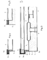
- FIG. 1 shows the absorber 1 and the pipeline configured in the absorber and similar to a meandering line. It can be seen from FIG. 2 that the edges of the absorber 1 are bent into the flanges 2 with a right-angled bend. In the vicinity of the flanges 2, the openings 7 preventing heat flow are provided, which theoretically are in several rows - e.g. B. moved like a checkerboard - can extend in the vicinity of the edges of the absorber. The task of the openings 7 is to prevent excessive heat loss through the flanges 2.
- those parts of the pipeline 6 are arranged which are assigned to the connecting pieces serving for the entry and exit of the heat transfer medium.
- the side of the absorber facing away from the sunlight can be provided with the claws 11, with the aid of which the thermal insulation cushion 4 (see FIG. 3) can be attached to the absorber.
- the thermal insulation pad is made of any plastic foam, such as. B. polystyrene foam.
- the claws are thus attached to the absorber 1 by inserting the heat insulating plate 10 between their surfaces, as a result of which the heat flow from the absorber via the claws. 11 can be prevented.
- the connecting pieces 9 are made of a heat insulating material and the heat-insulating surface strips 8 are inserted between the cover slats 5 which surround the entirety of the flanges 2 and the solar collector 5 as a frame.
- the cover plate 5 are - as can be seen from Figures 3, 4 and 5 - several tasks are assigned. The most important function of the connection with the flanges 3 already mentioned is to fasten or surround the translucent covers 3.
- the translucent cover 3 is attached to the side of the absorber 1 facing the sunlight and is made of glass, plastic and / or some transparent film.
- the translucent cover 3 can consist of one or more layers.
- the insert profile which also serves as a spacer, can be arranged along the edges.
- the protrusion 5a of the cover slat 5 serves to fasten the translucent cover 3, while the protrusion 5b of the same cover slat 5 fixes the thermal insulation pad 4.
- the heat insulating pad 4 can be provided on the side facing away from the sunlight with a protective film 12, which significantly increases the efficiency of the solar collector. It can be seen from FIGS. 4 and 5 that the translucent cover 3 is clamped into the projection 5a of the cover plate 5 via the clearing flanges 13.
Landscapes
- Engineering & Computer Science (AREA)
- Physics & Mathematics (AREA)
- Life Sciences & Earth Sciences (AREA)
- Sustainable Development (AREA)
- Sustainable Energy (AREA)
- Thermal Sciences (AREA)
- Chemical & Material Sciences (AREA)
- Combustion & Propulsion (AREA)
- Mechanical Engineering (AREA)
- General Engineering & Computer Science (AREA)
- Photovoltaic Devices (AREA)
- Heat-Exchange Devices With Radiators And Conduit Assemblies (AREA)
Applications Claiming Priority (2)
| Application Number | Priority Date | Filing Date | Title |
|---|---|---|---|
| HU80928A HU184740B (en) | 1980-04-16 | 1980-04-16 | Heat collector |
| HUEP000928 | 1980-04-16 |
Publications (2)
| Publication Number | Publication Date |
|---|---|
| EP0038074A2 true EP0038074A2 (fr) | 1981-10-21 |
| EP0038074A3 EP0038074A3 (fr) | 1981-12-30 |
Family
ID=10952081
Family Applications (1)
| Application Number | Title | Priority Date | Filing Date |
|---|---|---|---|
| EP81102845A Withdrawn EP0038074A3 (fr) | 1980-04-16 | 1981-04-14 | Collecteur solaire |
Country Status (2)
| Country | Link |
|---|---|
| EP (1) | EP0038074A3 (fr) |
| HU (1) | HU184740B (fr) |
Cited By (2)
| Publication number | Priority date | Publication date | Assignee | Title |
|---|---|---|---|---|
| GB2175995A (en) * | 1985-05-23 | 1986-12-10 | Russell Wing | Apparatus for heating fluid |
| GB2397642A (en) * | 2002-12-16 | 2004-07-28 | Philip Andrew Kennedy | Heat transfer element |
Family Cites Families (5)
| Publication number | Priority date | Publication date | Assignee | Title |
|---|---|---|---|---|
| US4010733A (en) * | 1975-06-03 | 1977-03-08 | The United States Of America As Represented By The United States Energy Research And Development Administration | Structurally integrated steel solar collector |
| FR2343208A1 (fr) * | 1976-03-01 | 1977-09-30 | Naizot Serge | Capteur d'energie solaire |
| DE2631771A1 (de) * | 1976-07-15 | 1978-01-19 | Eberspaecher J | Sonnenkollektoreinrichtung |
| FR2408018A2 (fr) * | 1977-11-02 | 1979-06-01 | Canavese Gerard | Adaptation d'un support et d'un dispositif en vue de realiser une paroi apte a capter le rayonnement solaire |
| FR2423733A1 (fr) * | 1978-04-19 | 1979-11-16 | Olin Corp | Panneau d'echange thermique |
-
1980
- 1980-04-16 HU HU80928A patent/HU184740B/hu unknown
-
1981
- 1981-04-14 EP EP81102845A patent/EP0038074A3/fr not_active Withdrawn
Cited By (2)
| Publication number | Priority date | Publication date | Assignee | Title |
|---|---|---|---|---|
| GB2175995A (en) * | 1985-05-23 | 1986-12-10 | Russell Wing | Apparatus for heating fluid |
| GB2397642A (en) * | 2002-12-16 | 2004-07-28 | Philip Andrew Kennedy | Heat transfer element |
Also Published As
| Publication number | Publication date |
|---|---|
| HU184740B (en) | 1984-10-29 |
| EP0038074A3 (fr) | 1981-12-30 |
Similar Documents
| Publication | Publication Date | Title |
|---|---|---|
| DE3042952C2 (fr) | ||
| DE2600826A1 (de) | Sonnenenergiekollektor | |
| DE2530152C2 (de) | Kollektorelemente zur Ausnutzung der Sonnenwärme | |
| DE102008029676B4 (de) | Sonnenkollektor mit mikrostrukturierter Absorberfläche | |
| EP0038074A2 (fr) | Collecteur solaire | |
| DE19908683C2 (de) | Radiatorstruktur eines Satelliten | |
| EP0079882B1 (fr) | Toiture avec elements de couverture se recouvrant comme des ecailles | |
| DE19756634C2 (de) | Plattenteil für Gebäude, Böden oder Schwimmbadanlagen | |
| DE202016003756U1 (de) | Photovoltaik-Modul mit Wärmetauscher für Solarstrahlungs- und Luft-Wärme | |
| DE102004010653B4 (de) | Hybrider Niedertemperatur-Solar-Kollektor in flexibler und selbstklebender Ausführung | |
| DE3046596A1 (de) | "sonnenenergiekollektor" | |
| DE202012103819U1 (de) | Solarkollektor mit einem Absorber | |
| DE29521415U1 (de) | Solarkollektor | |
| DE102011101212A1 (de) | Dach- und Fassaden-Leichtbauelement | |
| DE2649807A1 (de) | Sonnenkollektor | |
| DE102008013686A1 (de) | Solar-Kollektoren | |
| DE102007044252A1 (de) | Luftsonnenkollektorvorrichtung | |
| DE2544915A1 (de) | Sonnenkollektor | |
| DE2833122A1 (de) | Solarkollektor | |
| DE2633862A1 (de) | Sonnenkollektor | |
| DE2914244A1 (de) | Dach- und wandfertigteil mit sonnenwaermesammler | |
| DE2911913C2 (de) | Wärmetauschergruppe zur Aufnahme von Umgebungswärme oder zur Abgabe von Wärme an die Umgebung | |
| DE2850844A1 (de) | Dachziegel und dazugehoerige anordnung fuer eine dachabdeckung | |
| DE2837095A1 (de) | Solarkollektor | |
| DE102007031601A1 (de) | Gebäudeteil mit Wärmeaufnehmer |
Legal Events
| Date | Code | Title | Description |
|---|---|---|---|
| PUAI | Public reference made under article 153(3) epc to a published international application that has entered the european phase |
Free format text: ORIGINAL CODE: 0009012 |
|
| AK | Designated contracting states |
Designated state(s): AT CH DE FR IT |
|
| PUAL | Search report despatched |
Free format text: ORIGINAL CODE: 0009013 |
|
| AK | Designated contracting states |
Designated state(s): AT CH DE FR IT |
|
| 17P | Request for examination filed |
Effective date: 19820505 |
|
| STAA | Information on the status of an ep patent application or granted ep patent |
Free format text: STATUS: THE APPLICATION IS DEEMED TO BE WITHDRAWN |
|
| 18D | Application deemed to be withdrawn |
Effective date: 19830825 |
|
| RIN1 | Information on inventor provided before grant (corrected) |
Inventor name: MESZLENYI, ZOLTAN, DIPL.-ING. Inventor name: OERDOEGH, ZOLTAN, DR., DIPL.-ING. |