EP0038214A2 - Circuit de commande pulsé pour moteur à courant continu à aimant permanent - Google Patents
Circuit de commande pulsé pour moteur à courant continu à aimant permanent Download PDFInfo
- Publication number
- EP0038214A2 EP0038214A2 EP81301647A EP81301647A EP0038214A2 EP 0038214 A2 EP0038214 A2 EP 0038214A2 EP 81301647 A EP81301647 A EP 81301647A EP 81301647 A EP81301647 A EP 81301647A EP 0038214 A2 EP0038214 A2 EP 0038214A2
- Authority
- EP
- European Patent Office
- Prior art keywords
- armature
- transistor
- transistor switch
- thyristor
- motor
- Prior art date
- Legal status (The legal status is an assumption and is not a legal conclusion. Google has not performed a legal analysis and makes no representation as to the accuracy of the status listed.)
- Withdrawn
Links
Images


Classifications
-
- H—ELECTRICITY
- H02—GENERATION; CONVERSION OR DISTRIBUTION OF ELECTRIC POWER
- H02P—CONTROL OR REGULATION OF ELECTRIC MOTORS, ELECTRIC GENERATORS OR DYNAMO-ELECTRIC CONVERTERS; CONTROLLING TRANSFORMERS, REACTORS OR CHOKE COILS
- H02P7/00—Arrangements for regulating or controlling the speed or torque of electric DC motors
- H02P7/06—Arrangements for regulating or controlling the speed or torque of electric DC motors for regulating or controlling an individual DC dynamo-electric motor by varying field or armature current
- H02P7/18—Arrangements for regulating or controlling the speed or torque of electric DC motors for regulating or controlling an individual DC dynamo-electric motor by varying field or armature current by master control with auxiliary power
- H02P7/24—Arrangements for regulating or controlling the speed or torque of electric DC motors for regulating or controlling an individual DC dynamo-electric motor by varying field or armature current by master control with auxiliary power using discharge tubes or semiconductor devices
- H02P7/28—Arrangements for regulating or controlling the speed or torque of electric DC motors for regulating or controlling an individual DC dynamo-electric motor by varying field or armature current by master control with auxiliary power using discharge tubes or semiconductor devices using semiconductor devices
- H02P7/281—Arrangements for regulating or controlling the speed or torque of electric DC motors for regulating or controlling an individual DC dynamo-electric motor by varying field or armature current by master control with auxiliary power using discharge tubes or semiconductor devices using semiconductor devices the DC motor being operated in four quadrants
-
- H—ELECTRICITY
- H02—GENERATION; CONVERSION OR DISTRIBUTION OF ELECTRIC POWER
- H02P—CONTROL OR REGULATION OF ELECTRIC MOTORS, ELECTRIC GENERATORS OR DYNAMO-ELECTRIC CONVERTERS; CONTROLLING TRANSFORMERS, REACTORS OR CHOKE COILS
- H02P3/00—Arrangements for stopping or slowing electric motors, generators, or dynamo-electric converters
- H02P3/06—Arrangements for stopping or slowing electric motors, generators, or dynamo-electric converters for stopping or slowing an individual dynamo-electric motor or dynamo-electric converter
- H02P3/08—Arrangements for stopping or slowing electric motors, generators, or dynamo-electric converters for stopping or slowing an individual dynamo-electric motor or dynamo-electric converter for stopping or slowing a DC motor
- H02P3/12—Arrangements for stopping or slowing electric motors, generators, or dynamo-electric converters for stopping or slowing an individual dynamo-electric motor or dynamo-electric converter for stopping or slowing a DC motor by short-circuit or resistive braking
-
- H—ELECTRICITY
- H02—GENERATION; CONVERSION OR DISTRIBUTION OF ELECTRIC POWER
- H02P—CONTROL OR REGULATION OF ELECTRIC MOTORS, ELECTRIC GENERATORS OR DYNAMO-ELECTRIC CONVERTERS; CONTROLLING TRANSFORMERS, REACTORS OR CHOKE COILS
- H02P7/00—Arrangements for regulating or controlling the speed or torque of electric DC motors
- H02P7/03—Arrangements for regulating or controlling the speed or torque of electric DC motors for controlling the direction of rotation of DC motors
- H02P7/04—Arrangements for regulating or controlling the speed or torque of electric DC motors for controlling the direction of rotation of DC motors by means of a H-bridge circuit
Definitions
- This invention relates to pulse control circuits for permanent magnet d.c. motors, i.e. for d.c. motors in which the field is generated by a permanent magnet.
- d.c. motors particularly vehicle traction motors
- a braking torque is developed whilst the motor acts as a generator driving charging current to the battery.
- Pulse control circuits are known for wound-field d.c. motors in which regenerative braking is available. However, these circuits involve reversing the connections of the field winding to the supply, to reverse the direction of the voltage generated by the armature, and therefore cannot be employed with a permanent magnet motor.
- This invention consists in a pulse control circuit for a permanent magnet d.c. motor, comprising first and second thyristors and first and second transistor switches arranged in a bridge circuit with the thyristors in adjacent arms of the bridge and the first and second transistor switches in arms of the bridge opposite the first and second thyristors respectively, the d.c. supply being connected in use between the common junction of the two thyristors and the common junction of the two transistor switches, and the motor armature being connected in use between the junction of the first thyristor with the second transistor switch and the junction of the second thyristor with the first transistor switch, the arrangement being such that on conduction of the first thyristor and first transistor switch the voltage of the d.c.
- control means for applying a gating signal to a selected one of the first and second thyristors and for repetitively switching on and off the associated transistor switch thereby to drive the armature in the direction corresponding to the selected thyristor, a respective diode being connected in parallel with the series connection of the armature and each thyristor to provide a freewheel path for armature current during non-conducting periods of the associated transistor switch.
- control means is adapted to effect regenerative braking of the motor by repetitively switching on and off the transistor switch associated with drive of the motor in one direction whilst the armature is rotating in the opposite direction, the other transistor switch and both thyristors remaining non-conducting, a further respective diode being connected in parallel with the non-conducting transistor switch to provide with the operating transistor switch a closed loop for circulation of the armature current when the transistor switch is conducting and to provide, with the diode connected across the associated thyristor and the armature, a path through which the armature generated voltage can drive current to the d.c. supply when the transistor switch is non-conducting.
- the armature 10 of a d.c. motor having a field provided by a permanent magnet is supplied from a d.c. source such as a battery 12, through a pulse control circuit.
- the pulse control circuit comprises two thyristors 14 F and 15 R arranged in a bridge in such a manner that when thyristor 14 F and transistor 15 F are conducting (with thyristor 14 R and transistor 15 R non-conducting) current can flow from the battery 12 to the armature 10 in a direction to drive the motor in the "forward" direction, whereas on conduction of thyristor 14 R and transistor 15 R (with thyristor 14 F and transistor 15 F non-conducting) current can flow to the armature in a direction to drive the armature in the opposite, "reverse", direction.
- thyristor 14F and transistor 15 R are connected in series across the battery 12, and thyristor 14 R and transistor 15 F are similarly connected across the battery 12, with the armature 10 connected between the junction of the cathode of thyristor 14 F with the collector of transistor 15 R and the junction of the cathode of thyristor 14 R with the collector of transistor 15 F .
- a diode 16 F is connected in parallel with thyristor 14 R , the anode of the diode being connected to the cathode of thyristor 14R.
- the diode 16 F together with the thyristor 14 F , provides a freewheel path across the armature when the motor is driven "forwards", as described below.
- a diode 16 R is similarly connected in parallel with thyristor 14 F , to provide a freewheel path when the motor is in the "reverse" driving mode.
- a diode 17 R is connected across the collector-emitter path of transistor 15 F9 and a diode 17 F is similarly connected across the collector-emitter path of transistor 15 R .
- control circuitry 18 Conduction of thyristors 14 F and 14 R and of the transistors 15 F and 15 R is governed by control logic circuitry 18.
- the control circuit 18 includes a pulse-width modulated clock 30 which receives an input signal dependent on the desired mark-to-space ratio of switching of the transistor 15 F or 15 R .
- the input signal may be for example from an accelerator position sensor such as a potentiometer coupled to the accelerator pedal of a vehicle driven by the motor 10.
- the output of clock 30 is supplied through a direction selection and interlock circuit 34 and suitable driving circuits to the base of transistor 15 F or 15 R' to switch on the transistor at uniformly spaced intervals t on ( Figure 3) and to switch off the transistor at times toff which vary in dependence on the input signal to vary the periods of conduction of the transistor.
- the circuit 34 also receives an input from a direction selector 36, which may be a manually operated switch, the circuit 34 controlling the conduction of the thyristors 14F, 14 R and transistors 15 F , 15 R of the bridge circuit 20 in dependence on the drive direction selected by the direction selector 36 and on the direction of the voltage across the motor 10, as described below.
- the circuitry also includes a current limit circuit 38 which acts to limit the motor current during motoring and regenerative braking, as described below. The current limit circuit measures the motor current by monitoring the collector voltage of the transistor 15 F and 1 5 R .
- a continuous gating voltage is applied to the gate electrode of thyristor 14 F whilst transistor 15 F is rendered repetitively conducting and non-conducting. Thyristor 14 R and transistor 15 R remain non-conducting.
- transistor 15 F When transistor 15 F is conducting, current flows from the battery through thyristor 14 F armature 10 and transistor 15 F .
- the inductance of the armature maintains current flow through the closed loop consisting of diode 16 F and thyristor 14 F .
- transistor 15 F is held non-conducting and the gating signal to thyristor 14 F is removed.
- the control circuitry 18 begins to switch transistor 15 R repetitively on and off. As long as the motor armature 10 continues to rotate in the "forward” direction it will generate a voltage with the side of the armature connected to transistor 15 R positive with respect to the side connected to transistor 15 F .
- transistor 15 R when transistor 15 R is conducting, the armature-generated voltage drives current in the loop consisting of the armature 10, transistor 15 R and diode 17 R , producing a braking torque on the armature. Owing to the low inductance of the armature the current in this loop rises rapidly.
- transistor 15 R is turned off, the resulting fall in armature current produces an inductive voltage, in the same direction as the armature-generated voltage, which drives current through the circuit consisting of the armature 10, diode 16 R , battery 12 and diode 17 R , the inductive energy being thus transferred from the armature to the battery.
- transistor 15 R When transistor 15 R is switched on again, the armature current again builds up in the loop including the transistor 15 F and diode 17 R .
- Regenerative braking can be initiated by changing over the direction selector 36 when the motor is rotating, the logic circuitry sensing the direction of the armature generated voltage and switching the circuit to the regenerative braking mode until the armature voltage has fallen below a predetermined low level.
- the logic circuitry also acts to switch the circuit to the regenerative braking mode if the motor speed demanded by the input to the circuit falls to zero, for example if the driver of the vehicle lifts his foot from the accelerator pedal or moves the direction selector switch to a neutral position, so that the motor speed is brought gradually to zero.
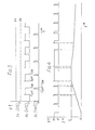
- Figure 3 shows the voltage V across the collector-emitter circuit of transistor 15 F during forward motoring.
- the waveforms 3a, 3b and 3c show the voltage at zero demand, 50% demand and 100% demand respectively.
- the transistor is switched at the maximum mark-to-space ratio, i.e. with the length of the non-conducting periods reduced to a minimum. If, during a period of conduction of the transistor 15F, the motor current exceeds a predetermined value, the transistor 15 F is immediately turned off and is not turned on again until the end of the next succeeding clock cycle. In these "off" periods the demand signal supplied to the clock circuit 30 is attenuated within the circuit 30, so that when the current limit conditions end, i.e. when the motor current fails to reach the predetermined level during an "on" period of the transistor, the mark-to-space ratio of switching has been reduced and gradually rises again to the level set by the signal from the accelerator position sensor 32.
- the circuit 18 switches transistor 15 R on and off at a relatively high mark-to-space ratio, so that the motor current I rises to the current limit level I L .
- the current limit circuit then comes into operation, so that the motor current, and therefore the braking torque, is controlled.
- the mark-to-space ratio gradually rises again. Since the motor speed and therefore the motor-generated voltage is decreasing, the motor current falls, but the rate of decrease of motor current is reduced by the increase in mark-to-space ratio. The braking torque on the motor is therefore maintained until the motor speed falls to a low value.
Landscapes
- Engineering & Computer Science (AREA)
- Power Engineering (AREA)
- Stopping Of Electric Motors (AREA)
- Control Of Direct Current Motors (AREA)
Applications Claiming Priority (2)
| Application Number | Priority Date | Filing Date | Title |
|---|---|---|---|
| GB8012410 | 1980-04-15 | ||
| GB8012410 | 1980-04-15 |
Publications (2)
| Publication Number | Publication Date |
|---|---|
| EP0038214A2 true EP0038214A2 (fr) | 1981-10-21 |
| EP0038214A3 EP0038214A3 (fr) | 1982-06-09 |
Family
ID=10512803
Family Applications (1)
| Application Number | Title | Priority Date | Filing Date |
|---|---|---|---|
| EP81301647A Withdrawn EP0038214A3 (fr) | 1980-04-15 | 1981-04-14 | Circuit de commande pulsé pour moteur à courant continu à aimant permanent |
Country Status (1)
| Country | Link |
|---|---|
| EP (1) | EP0038214A3 (fr) |
Cited By (14)
| Publication number | Priority date | Publication date | Assignee | Title |
|---|---|---|---|---|
| EP0093555A1 (fr) * | 1982-04-30 | 1983-11-09 | Westinghouse Electric Corporation | Dispositif de commande pour un moteur de véhicule |
| EP0097145A3 (en) * | 1982-06-16 | 1984-04-25 | Friedmann & Maier Aktiengesellschaft | Circuit arrangement |
| FR2551276A1 (fr) * | 1983-08-26 | 1985-03-01 | Elevator Gmbh | Procede d'elaboration de la tension de commande du moteur a courant continu d'un ascenseur et dispositif pour la mise en oeuvre de ce procede |
| GB2163017A (en) * | 1984-08-06 | 1986-02-12 | Ex Cell O Corp | Dc motor control system |
| EP0186282A1 (fr) * | 1984-11-26 | 1986-07-02 | General Motors Corporation | Appareil pour l'entraînement d'une fenêtre d'un véhicule automobile |
| EP0343428A1 (fr) * | 1988-05-21 | 1989-11-29 | Robert Bosch Gmbh | Circuit en pont à semi-conducteur |
| FR2687863A1 (fr) * | 1992-02-25 | 1993-08-27 | Rahban Thierry | Convertisseur d'energie pour charge quatre quadrants. |
| US5617000A (en) * | 1995-04-13 | 1997-04-01 | Alps Electric Co., Ltd. | Apparatus for detecting and controlling the rotational position of a motor shaft |
| EP1369987A3 (fr) * | 2002-05-29 | 2004-05-06 | Siemens Aktiengesellschaft | Pont en H |
| WO2005099081A1 (fr) * | 2004-04-08 | 2005-10-20 | Robert Bosch Gmbh | Ensemble circuit et procede pour freiner par court-circuit un moteur a courant continu |
| EP1434338A3 (fr) * | 2002-12-27 | 2009-01-21 | Calsonic Kansei Corporation | Dispositif de commande d'actionnement d'un actuateur |
| EP1411626A3 (fr) * | 2002-10-18 | 2015-08-19 | Black & Decker Inc. | Dispositif et méthode pour le freinage d'un moteur |
| CN108233798A (zh) * | 2018-01-29 | 2018-06-29 | 昆明理工大学 | 一种双闭环直流电机控制电路 |
| US10720860B2 (en) | 2018-01-03 | 2020-07-21 | Milwaukee Electric Tool Corporation | Electronic braking in a power tool |
Family Cites Families (3)
| Publication number | Priority date | Publication date | Assignee | Title |
|---|---|---|---|---|
| DE1956748A1 (de) * | 1969-11-12 | 1971-05-19 | Licentia Gmbh | Schaltungsanordnung zum Antrieb eines Gleichstrommotors in einer Brueckenschaltung mit vier in deren Zweigen liegenden gesteuerten Halbleiterelementen |
| DE2233188A1 (de) * | 1972-07-06 | 1974-01-24 | Kiepe Bahn Elektrik Gmbh | Schaltungsanordnung fuer einen gleichstrom-nebenschlussmotor mit impulssteuerung und umkehrbarer drehrichtung |
| FR2434511A1 (fr) * | 1978-07-27 | 1980-03-21 | Dba | Procede pour commander la vitesse de rotation d'un moteur a courant continu a commande par l'induit, et dispositif d'alimentation pour un tel moteur a courant continu |
-
1981
- 1981-04-14 EP EP81301647A patent/EP0038214A3/fr not_active Withdrawn
Cited By (19)
| Publication number | Priority date | Publication date | Assignee | Title |
|---|---|---|---|---|
| EP0093555A1 (fr) * | 1982-04-30 | 1983-11-09 | Westinghouse Electric Corporation | Dispositif de commande pour un moteur de véhicule |
| EP0097145A3 (en) * | 1982-06-16 | 1984-04-25 | Friedmann & Maier Aktiengesellschaft | Circuit arrangement |
| FR2551276A1 (fr) * | 1983-08-26 | 1985-03-01 | Elevator Gmbh | Procede d'elaboration de la tension de commande du moteur a courant continu d'un ascenseur et dispositif pour la mise en oeuvre de ce procede |
| GB2163017A (en) * | 1984-08-06 | 1986-02-12 | Ex Cell O Corp | Dc motor control system |
| EP0186282A1 (fr) * | 1984-11-26 | 1986-07-02 | General Motors Corporation | Appareil pour l'entraînement d'une fenêtre d'un véhicule automobile |
| EP0343428A1 (fr) * | 1988-05-21 | 1989-11-29 | Robert Bosch Gmbh | Circuit en pont à semi-conducteur |
| FR2687863A1 (fr) * | 1992-02-25 | 1993-08-27 | Rahban Thierry | Convertisseur d'energie pour charge quatre quadrants. |
| US5617000A (en) * | 1995-04-13 | 1997-04-01 | Alps Electric Co., Ltd. | Apparatus for detecting and controlling the rotational position of a motor shaft |
| EP1369987A3 (fr) * | 2002-05-29 | 2004-05-06 | Siemens Aktiengesellschaft | Pont en H |
| US6989643B2 (en) | 2002-05-29 | 2006-01-24 | Siemens Aktiegesellschaft | Electrical drive apparatus which can be operated via a full-bridge circuit, with a different load depending on the drive direction |
| EP1411626A3 (fr) * | 2002-10-18 | 2015-08-19 | Black & Decker Inc. | Dispositif et méthode pour le freinage d'un moteur |
| EP1434338A3 (fr) * | 2002-12-27 | 2009-01-21 | Calsonic Kansei Corporation | Dispositif de commande d'actionnement d'un actuateur |
| WO2005099081A1 (fr) * | 2004-04-08 | 2005-10-20 | Robert Bosch Gmbh | Ensemble circuit et procede pour freiner par court-circuit un moteur a courant continu |
| US10720860B2 (en) | 2018-01-03 | 2020-07-21 | Milwaukee Electric Tool Corporation | Electronic braking in a power tool |
| US11075594B2 (en) | 2018-01-03 | 2021-07-27 | Milwaukee Electric Tool Corporation | Electronic braking in a power tool |
| US11695352B2 (en) | 2018-01-03 | 2023-07-04 | Milwaukee Electric Tool Corporation | Electronic braking in a power tool |
| US12166447B2 (en) | 2018-01-03 | 2024-12-10 | Milwaukee Electric Tool Corporation | Electronic braking in a power tool |
| CN108233798A (zh) * | 2018-01-29 | 2018-06-29 | 昆明理工大学 | 一种双闭环直流电机控制电路 |
| CN108233798B (zh) * | 2018-01-29 | 2023-09-26 | 昆明理工大学 | 一种双闭环直流电机控制电路 |
Also Published As
| Publication number | Publication date |
|---|---|
| EP0038214A3 (fr) | 1982-06-09 |
Similar Documents
| Publication | Publication Date | Title |
|---|---|---|
| US5332954A (en) | Optimal DC motor/controller configuration | |
| EP0235074B1 (fr) | Commande de vitesse pour un système d'essuie-glace | |
| EP0038214A2 (fr) | Circuit de commande pulsé pour moteur à courant continu à aimant permanent | |
| US4705997A (en) | Bidirectional motor drive circuit | |
| US5283470A (en) | Hybrid drive system with regeneration for motor vehicles and the like with a brushless motor | |
| US4388573A (en) | Electric vehicle control device | |
| EP0036326B1 (fr) | Système de freinage à récupération pour un moteur à courant continu à trois bornes commandé par impulsion | |
| JPH08322106A (ja) | モータの制御方法 | |
| EP0476152B1 (fr) | Dispositif d'attaque pour moteur a reluctance variable | |
| US5789896A (en) | Apparatus and method for controlling an electric motor having an armature and a series-wound, series-connected field coil that can be separately controlled during regenerative braking | |
| WO1990016111A1 (fr) | Dispositif de commande d'un moteur a reluctance | |
| US4267492A (en) | Control circuit for a D.C. motor | |
| US5436825A (en) | Electronic control circuit for the supply of ohmic-inductive loads by means of direct-current pulses | |
| JPS60121975A (ja) | 直流モータの制動装置 | |
| US4385266A (en) | Field weakening system for pulse-controlled three-terminal d.c. motor | |
| US4042865A (en) | Separately excited D.C. motors | |
| US3688169A (en) | Brushless motor control apparatus for an electric vehicle | |
| JP3541238B2 (ja) | モータ駆動用電源装置 | |
| GB1460741A (fr) | ||
| JPS607472B2 (ja) | 電動機の制御装置 | |
| JPH0218715Y2 (fr) | ||
| JP3400917B2 (ja) | 無整流子電動機の始動制御方法 | |
| JPS56112892A (en) | Controlling method for pole change type induction motor | |
| SU739707A1 (ru) | Способ управлени тиристорами мостового преобразовател посто нного тока и устройство дл его осуществлени | |
| SU661711A1 (ru) | Устройство дл управлени тиристорным преобразователем электропривода посто нного тока |
Legal Events
| Date | Code | Title | Description |
|---|---|---|---|
| PUAI | Public reference made under article 153(3) epc to a published international application that has entered the european phase |
Free format text: ORIGINAL CODE: 0009012 |
|
| AK | Designated contracting states |
Designated state(s): DE FR GB IT SE |
|
| PUAL | Search report despatched |
Free format text: ORIGINAL CODE: 0009013 |
|
| AK | Designated contracting states |
Designated state(s): DE FR GB IT SE |
|
| STAA | Information on the status of an ep patent application or granted ep patent |
Free format text: STATUS: THE APPLICATION IS DEEMED TO BE WITHDRAWN |
|
| 18D | Application deemed to be withdrawn |
Effective date: 19830515 |
|
| RIN1 | Information on inventor provided before grant (corrected) |
Inventor name: SLOAN, ALBERT EVERETT |