EP0038432A1 - Dispositif de désempilage de piles, notamment constituées de pièces de bois allongées - Google Patents
Dispositif de désempilage de piles, notamment constituées de pièces de bois allongées Download PDFInfo
- Publication number
- EP0038432A1 EP0038432A1 EP81102303A EP81102303A EP0038432A1 EP 0038432 A1 EP0038432 A1 EP 0038432A1 EP 81102303 A EP81102303 A EP 81102303A EP 81102303 A EP81102303 A EP 81102303A EP 0038432 A1 EP0038432 A1 EP 0038432A1
- Authority
- EP
- European Patent Office
- Prior art keywords
- stack
- layer
- sliding
- stacking
- support element
- Prior art date
- Legal status (The legal status is an assumption and is not a legal conclusion. Google has not performed a legal analysis and makes no representation as to the accuracy of the status listed.)
- Granted
Links
- 239000002023 wood Substances 0.000 title claims 2
- 238000012545 processing Methods 0.000 claims abstract description 6
- 238000003825 pressing Methods 0.000 claims description 2
- 241000446313 Lamella Species 0.000 claims 2
- 230000000712 assembly Effects 0.000 claims 1
- 238000000429 assembly Methods 0.000 claims 1
- 238000006073 displacement reaction Methods 0.000 claims 1
- 238000012546 transfer Methods 0.000 abstract description 3
- 238000013461 design Methods 0.000 description 2
- 238000011161 development Methods 0.000 description 2
- 230000018109 developmental process Effects 0.000 description 2
- 238000000151 deposition Methods 0.000 description 1
- 238000000034 method Methods 0.000 description 1
- 210000002023 somite Anatomy 0.000 description 1
Images



Classifications
-
- B—PERFORMING OPERATIONS; TRANSPORTING
- B65—CONVEYING; PACKING; STORING; HANDLING THIN OR FILAMENTARY MATERIAL
- B65G—TRANSPORT OR STORAGE DEVICES, e.g. CONVEYORS FOR LOADING OR TIPPING, SHOP CONVEYOR SYSTEMS OR PNEUMATIC TUBE CONVEYORS
- B65G59/00—De-stacking of articles
- B65G59/02—De-stacking from the top of the stack
Definitions
- the invention relates to a device for layer-by-layer unstacking, in particular piles layered from elongated profiled timber according to the features of the preamble of patent claim 1.
- the full length of the stack layer is pushed off the stack and onto the receiving device located behind the stack spent, from which the stack layer is separated into its individual stack layer elements.
- Such a device is at least twice as long as the total length of the stack. This requires a considerable amount of space.
- the time required for the complete pushing of a complete stack layer in its entire length from the stack is very time-consuming.
- a device for automatic loading is also known. From processing machines with an elongated profile parts removed from a layered stack. With this device, a stack layer is pushed off the stack by means of stops and then separated by moving the individual stack layer elements in the longitudinal direction. Cross sliding is only possible, however, if the sliding surface is absolutely flat, i.e. if all stacking layer elements have exactly the same thickness dimensions and are absolutely flat, i.e. not bent, twisted or the like, or if several intermediate strips lie regularly on the stack between two stacking layers. Since the ideal case of absolutely flat, non-bent, non-twisted stacking layer elements is only rarely present, it is practically only possible to push a stacking layer crosswise if there are intermediate strips.
- the invention is therefore based on the object of a device for layer-by-layer unstacking, in particular stacked from elongated profiled timber.
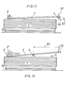
- each individual stack layer is pushed only by a small amount in the longitudinal direction of the stack by means of the sliding device, so that the end of the stack layer opposite the sliding device is just on the supporting element comes into contact with the top edge immediately below the bottom edge of the pushed stacking layer in front of the corresponding end face of the stack.
- the stacking layer is released from the stack, so that support arms can be moved one after the other transversely under the raised stacking layer, which take over the stacking layer in order to further separate it.
- the device according to the invention has only a slightly larger space requirement than the stack itself. Pushing the individual Stacking is done in a short way in the shortest possible time.
- the sliding device comprises individual slats which are arranged next to one another and can be moved independently of one another and which automatically attach themselves to the ends of the individual stacking layer elements which are formed differently, if appropriate.
- the sliding device can expediently be moved back and forth in the vertical direction.
- a holding-down device for the stacking layer is arranged above the support element.
- the stacked position raised by the support element can be pivoted around the support element itself, with the sliding device being lifted or moved vertically at the same time.
- the stack layer is released from the stack so that the support arms can be extended transversely to take over the stack layer.
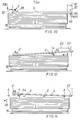
- the support element is mounted so as to be movable substantially horizontally toward and away from the sliding device. This enables the support element to be lifted between the stack and the stack in the direction of the stack Sliding device can be moved, so that the pushed stack position is gradually raised, so that the support arms can be moved successively across the raised stack position as soon as the support element has passed the area of the support arm to be extended.
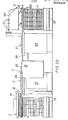
- the device shown in a top view in FIG. 1 for layer-by-layer unstacking, in particular stacked from elongated profiled timber comprises a transversely arranged pushing device 2 for pushing a stack layer 3 on one end face of the stack 1, and a support element 4 for pushing it on the opposite end face of the stack 1 Inclusion of one end of the stacking layer 3 pushed by means of the sliding device 2 and a machine 5 arranged next to the stack 1 with horizontally movable back and forth arms 6 across the stack 1 for taking over the stacking layer 3 and separating into individual stacking layer elements 7 be fed via a roller table 8 and a bullet accelerator 9 in the direction of arrow 10 to a processing machine, not shown.
- the device further comprises a guideway 11 for the horizontal movement of the support element 4 and columns 12, 13 for mounting the guideway 11 and the sliding device 2.
- FIG. 2 corresponds to the embodiment according to FIG. 1.
- the columns 12 a portal which carries the sliding device 2 on its crossbar 14.
- the stack 1 is mounted on a lifting table 15, which can be moved vertically by one stack layer height after each stack layer 3 has been removed.
- the embodiment shown in FIG. 3 differs from the embodiment according to FIG. 2 only in that only one column 12 with a crossbar 14 is provided for receiving the sliding device 2.
- the column 12 stands between the stack 1 and the automatic de-stacking machine 5.
- the column 13 and the guideway 11 present between the columns 12, 13 are also arranged between the stack 1 and the automatic de-stacking machine 5, but in any case outside the narrow end faces of the stack 1.
- the sliding device 2 shown in FIGS. 4, 5 and 6 is mounted within a horizontally arranged U-shaped frame 16 which is fastened to the crossbar 14.
- the sliding device 2 consists of a rectangular frame 17, which is pivotably supported by means of two downwardly extending lugs 18 on a tubular traverse 19 located at the front end of the frame 16.
- the rectangular frame 17 On hinteren.Ende the rectangular frame 17 is supported by means of a Z ylinderkolbenizi 20 on the crossbar fourteenth Below both longitudinal sides of the rectangular frame 17, guide rods 21 extend, which at the front end in the lugs 18th and are attached at the rear end in corresponding lugs 22.
- a slat guide plate 23 extends across the stack 1, which is guided on both sides with two guide bushings 24 on the guide rods 21.
- chain drives 25 are provided on both sides of the long sides of the rectangular frame 17, which can be driven via drives, not shown in detail.
- the chain drives 25 are connected to the slat guide plate -23 via chain links 26, which are fastened to the front guide bushes 24 in each case.
- a guide rod 27 extends across the stack 1 and is mounted on both narrow sides of the slat guide plate 23.
- the guide rod 27 carries a plurality of sliding lamellae 28 arranged side by side in the sliding direction, which are provided with approximately centrally arranged projections 29, in which approximately vertically extending elongated holes 30 are made, through which the guide rod 27 extends.
- the individual sliding lamellae 28 have a heavy front end 31 rounded downward and a lighter rear end 32 designed like a hook downward. With the rounded front end 31, the sliding slats rest on the individual stack layers 3 of the stack 1.
- a limiting stop 33 which extends across them and is fastened below the slat guide plate 23.
- the pusher 2 can be pivoted about the axis of the tubular cross member 19, so as upon lifting a stack location to allow Mitschul.der 3 is a vertical shifter. 2
- the guideway 11 consists essentially of a box girder 34 with a square cross section, which is supported at one end in the column 12 via a pivot bearing 35 and is connected at the other end by means of a connecting piece 36 to a chain link 37 of a chain drive 38 which around two chain wheels 39, 40 mounted in the column 1.3 can be moved vertically back and forth (arrow 41). This movement is not closer to one. causes cylinder piston unit shown, which engages the chain drive 38.
- a console 42 is attached to the column 13 for the rest position of the guideway 11.
- the support element 4 can be moved back and forth along the box girder 34 of the guideway 11.
- This consists of a rectangular frame 43 mounted on one side on the box girder 34, in which two rollers 44, 45 extending across the stack 1 are supported on both sides in the narrow sides of the rectangular frame 43.
- the rollers 44, 45 protrude with their outer surfaces of the top of the rectangular frame 43.
- Both chain elements 46, 47 and 48 can be driven via the chain drives 46, 47 and 48, not shown, both the support element 4 along the guideway 11 and the individual rollers 44, 45.
- the storage of the rectangular frame 43 on the box girder 34 takes place in pairs of rollers 49 to 53 arranged side by side, of which the rollers 49 on the top, the rollers -51 on the bottom and the rollers 52 are supported directly on the inside of the box girder 34.
- a guide track 54 is fastened to the box girder.
- a guide track 55 is fastened to the box girder.
- a further box girder 56 which is substantially smaller in cross section.
- a hold-down device 57 extends across the support element 4.
- This essentially consists of a transverse plate 58 and two Distance pressing devices 59. These are attached to a cantilever beam 60, which is at the upper end. the column 13 is fixed.
- the sliding device 2 With further movement of the support element 4 in the direction of the sliding device 2 (arrow 63 in FIG. 13), together with the stacking layer 3, the sliding device 2 is raised by a small amount (position. * 2 'in FIG. 13). During the horizontal movement of the support element 4 in the direction of arrow 63, further support arms 6 are extended under the raised stacking position 3. After the support element 4 (FIG. 14) has been completely extended, the stack layer 3 is placed on the support arms 6. These are then retracted again in a manner not shown in detail, the stacking layer 3 being brought onto the automatic destacker 5 described later.
- the support element 4 is assigned a brush element 64 which, during the horizontal movement of the support element 4 via the stack 1, takes any intermediate 100 (not shown) there and carries it in Direction of arrow 65 (Fig. 14) throws.
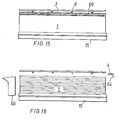
- the ejected intermediate strips can be introduced directly into a container 66 or, according to FIG. 19, fed to a discharge conveyor belt 68 via an inclined surface 67.
- pushing-off brushes 69 for intermediate strips can be attached transversely below each support arm, which, when the associated support arm 6 is extended, discharge the intermediate strips 100 into a container -70 located in front of the stack 1 (FIG. 16 ).
- container 70 guide plates 71 can also be used, which feed the extended Z intermediate strips to a conveyor belt 68 (FIG. 17).
- the machine 5 shown in FIG. 1 for unstacking individual stack layers 3 that have been taken over comprises a base frame 72 and three displaceable side stands 73, each of which has one of the support arms 6.
- the base frame 72 also carries a control cabinet 74 for receiving a control device for the various movement sequences described here. 20 and 21, the upper region of a side stand 73 is shown.
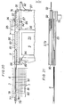
- the side stand 73 has a stacking unit 74, in which the support arm 6 is guided over rollers (not shown) and can be moved in and out by motor, for which purpose a flange motor 75 serves.
- the support arm 6 has at its free end a T RAG arm tip and immediately behind a slot 76 in which a pawl 77 is pivotally mounted about a pivot point 78th
- the pawl has a pawl hook 79 at the front end and a wedge surface 80 at the rear end against which a pawl wedge 81 bears, which can be actuated by a wedge slide 82.
- This is actuated by the vertical lever arm - a rectangular lever, not shown, in whose horizontal lever arm a roller is mounted.
- This is in engagement with a pawl lifting rail 83 which is mounted in the stacking unit 74 by means of two lifting rail cylinders 84 so that it can be raised and lowered vertically.
- the stacking layer 3 located on the storage surface 85 of the side stand 73 is taken over by a conveyor chain 86, which is deflected around chain wheels 87, 88.
- the sprocket 88 can be pivoted by means of a chain -lifting cylinder 89, so that the chain ver from a level below the storage surface 85 to a -plane above the storage surface 85 of the side stand 73 can be pivoted, in which the stack position 3 is on the conveyor chain 86 ..
- the support arm 6 can be extended again, at the same time the pawl 77 is pivoted back in with its pawl hook 79 by lowering the pawl lifting rail 83.
- the conveyor chain 86 is guided by a chain case 90, which is arranged next to the stacking unit 74.
- Each side stand 73 Comprises on its rear side a revolving chain conveyor 91. With parallel running circumferential drivers 92 with vertical stops 93 and slightly inclined storage surfaces 94 for individual stacking layer elements 7. As shown in FIG. 20, the conveyor chain 86 'moves the one on it Stacking layer 3 step by step (arrow 95), so that the drivers 92 moved vertically upward in the direction of arrow 96 with their receiving surfaces 94 each grip a stacking layer element 7 and on the right side in the direction of arrow 97 downward onto the roller table 8 can convey away, from which the individual stack layer elements 7 are fed via the bullet accelerator 9 to a processing machine (not shown).
- a stacking machine 98 can be arranged behind the automatic destacking machine 5 in the direction of movement, according to FIG. which can be extended by means of further support arms 6 'and placed on a new stack 1' above a further lifting table 15 '.
- the individual stack layer elements 7 ' can be deposited from one another with an air gap.
- Intermediate strips 100 which are fed from a strip magazine 101, can be placed between each two new stack layers 3 '.
- a compactly stacked stack 1 can be stacked to form a ventilable dry stack 1 ', the individual stacking layer elements 7' of which are arranged separately from one another with vertical and horizontal air gaps.
Landscapes
- Stacking Of Articles And Auxiliary Devices (AREA)
- De-Stacking Of Articles (AREA)
- Sheets, Magazines, And Separation Thereof (AREA)
- Placing Or Removing Of Piles Or Sheet Piles, Or Accessories Thereof (AREA)
- Piles And Underground Anchors (AREA)
- Debarking, Splitting, And Disintegration Of Timber (AREA)
- Forming Counted Batches (AREA)
Priority Applications (1)
| Application Number | Priority Date | Filing Date | Title |
|---|---|---|---|
| AT81102303T ATE7681T1 (de) | 1980-04-21 | 1981-03-27 | Vorrichtung zum lagenweisen entstapeln insbesondere aus langgestreckten profilhoelzern geschichteter stapel. |
Applications Claiming Priority (2)
| Application Number | Priority Date | Filing Date | Title |
|---|---|---|---|
| DE3015648 | 1980-04-21 | ||
| DE3015648A DE3015648C2 (de) | 1980-04-21 | 1980-04-21 | Vorrichtung zum lagenweisen Entstapeln aus langgestreckten Profilhölzern geschichteter Stapel |
Publications (2)
| Publication Number | Publication Date |
|---|---|
| EP0038432A1 true EP0038432A1 (fr) | 1981-10-28 |
| EP0038432B1 EP0038432B1 (fr) | 1984-05-30 |
Family
ID=6100759
Family Applications (1)
| Application Number | Title | Priority Date | Filing Date |
|---|---|---|---|
| EP81102303A Expired EP0038432B1 (fr) | 1980-04-21 | 1981-03-27 | Dispositif de désempilage de piles, notamment constituées de pièces de bois allongées |
Country Status (5)
| Country | Link |
|---|---|
| US (1) | US4417836A (fr) |
| EP (1) | EP0038432B1 (fr) |
| JP (1) | JPS56165629A (fr) |
| AT (1) | ATE7681T1 (fr) |
| DE (2) | DE3015648C2 (fr) |
Cited By (1)
| Publication number | Priority date | Publication date | Assignee | Title |
|---|---|---|---|---|
| DE102024100865A1 (de) | 2023-02-02 | 2024-08-08 | Stoiber Gmbh | Vorrichtung zum lageweisen Entstapeln eines Brettstapels |
Families Citing this family (7)
| Publication number | Priority date | Publication date | Assignee | Title |
|---|---|---|---|---|
| DE3941214C1 (fr) * | 1989-12-14 | 1991-01-03 | Hailo-Werk Rudolf Loh Gmbh & Co Kg, 6342 Haiger, De | |
| US5314297A (en) * | 1991-12-02 | 1994-05-24 | Herndon Oma L | Method and apparatus for stack separator and restacker |
| DE10057690C2 (de) * | 2000-11-21 | 2003-10-09 | Ludwig Walter | Verfahren und Vorrichtung zum automatischen Abstapeln, Vereinzeln und Zuteilen von Vierkanthölzern |
| DE20105444U1 (de) | 2001-02-01 | 2001-08-23 | H.I.T. Bertele GmbH + Co, 86833 Ettringen | Vorrichtung zur Vereinzelung von in einem Stapel vorliegenden Gegenständen, insbesondere von Dielen oder Brettern |
| NL1018548C1 (nl) * | 2001-07-16 | 2003-01-17 | Machf Roerstreek B V | Inrichting en werkwijze voor het ontstapelen van een stapeling en houtverwerkingsmachine voorzien van een dergelijke inrichting. |
| JP2005320158A (ja) * | 2004-05-03 | 2005-11-17 | Helmut Steinhilber | パイルの記録媒体のシートをさばく方法および装置 |
| US11702301B2 (en) * | 2021-02-24 | 2023-07-18 | Jacob The Losen | Material handling systems and methods for selecting and removing items from a bundle |
Citations (3)
| Publication number | Priority date | Publication date | Assignee | Title |
|---|---|---|---|---|
| DE2323227B2 (de) * | 1973-05-09 | 1975-08-21 | E. Albers & V. Drathen, 2223 Meldorf | Vorrichtung zum selbsttätigen Beschicken von Werkzeugmaschinen mit einem geschichteten Stapel entnommenen, langgestreckten Profilteilen |
| DE2549234A1 (de) * | 1975-07-21 | 1977-02-03 | Albret Soc Nouv D | Schiebevorrichtung zum beschicken einer ueberfurniermaschine |
| DE2551846A1 (de) * | 1975-11-19 | 1977-06-02 | Ind Planungs Ges Mbh | Einrichtung zum stirnseitigen abschieben von brettern bei einer abstapelanlage |
Family Cites Families (12)
| Publication number | Priority date | Publication date | Assignee | Title |
|---|---|---|---|---|
| US256511A (en) * | 1882-04-18 | Apparatus | ||
| US2672244A (en) * | 1953-01-15 | 1954-03-16 | Robert J Van Schie | Sheet separating and feeding device |
| US3067885A (en) * | 1959-02-24 | 1962-12-11 | Conrad D Kohler | Automatic panel feeder |
| US3565266A (en) * | 1968-09-17 | 1971-02-23 | Buss Automation Inc | Lumber breakdown hoist |
| CH513061A (de) * | 1970-03-16 | 1971-09-30 | Intercont Ferromatic Trust Reg | Anlage zum Paketieren von Langgut |
| DE2138119C3 (de) * | 1970-08-10 | 1981-01-29 | Roeder & Spengler Ohg, 6000 Bergen- Enkheim | Vorrichtung zum Stapeln von Zuschnitten o.dgl. Stapelgut |
| US3870167A (en) * | 1973-10-03 | 1975-03-11 | Kimberly Clark Co | Sheet pulp separator and feeder for baled pulp |
| US3991893A (en) * | 1974-05-20 | 1976-11-16 | Lynch Jack M | Coil lifting apparatus and method |
| DE2433128A1 (de) * | 1974-07-10 | 1976-01-22 | Righi Vertriebs Gmbh | Verfahren und vorrichtung zum abgreifen eines oberen plattenbuendels von einem plattenstapel |
| DE2639676C2 (de) * | 1976-09-03 | 1985-10-03 | Maschinenbau Oppenweiler Gmbh, 7155 Oppenweiler | Vorrichtung zum Beschicken eines Rundstapelbogenanlegers |
| JPS543511U (fr) * | 1977-06-08 | 1979-01-11 | ||
| SU734106A1 (ru) * | 1977-10-03 | 1980-05-15 | Белорусский Технологический Институт Имени С.М.Кирова | Устройство дл разборки пакетов пиломатериалов |
-
1980
- 1980-04-21 DE DE3015648A patent/DE3015648C2/de not_active Expired
-
1981
- 1981-03-27 AT AT81102303T patent/ATE7681T1/de not_active IP Right Cessation
- 1981-03-27 EP EP81102303A patent/EP0038432B1/fr not_active Expired
- 1981-03-27 DE DE8181102303T patent/DE3163839D1/de not_active Expired
- 1981-04-21 US US06/256,010 patent/US4417836A/en not_active Expired - Fee Related
- 1981-04-21 JP JP6052281A patent/JPS56165629A/ja active Granted
Patent Citations (3)
| Publication number | Priority date | Publication date | Assignee | Title |
|---|---|---|---|---|
| DE2323227B2 (de) * | 1973-05-09 | 1975-08-21 | E. Albers & V. Drathen, 2223 Meldorf | Vorrichtung zum selbsttätigen Beschicken von Werkzeugmaschinen mit einem geschichteten Stapel entnommenen, langgestreckten Profilteilen |
| DE2549234A1 (de) * | 1975-07-21 | 1977-02-03 | Albret Soc Nouv D | Schiebevorrichtung zum beschicken einer ueberfurniermaschine |
| DE2551846A1 (de) * | 1975-11-19 | 1977-06-02 | Ind Planungs Ges Mbh | Einrichtung zum stirnseitigen abschieben von brettern bei einer abstapelanlage |
Cited By (1)
| Publication number | Priority date | Publication date | Assignee | Title |
|---|---|---|---|---|
| DE102024100865A1 (de) | 2023-02-02 | 2024-08-08 | Stoiber Gmbh | Vorrichtung zum lageweisen Entstapeln eines Brettstapels |
Also Published As
| Publication number | Publication date |
|---|---|
| DE3015648C2 (de) | 1982-06-16 |
| US4417836A (en) | 1983-11-29 |
| JPS6319413B2 (fr) | 1988-04-22 |
| EP0038432B1 (fr) | 1984-05-30 |
| JPS56165629A (en) | 1981-12-19 |
| ATE7681T1 (de) | 1984-06-15 |
| DE3163839D1 (en) | 1984-07-05 |
| DE3015648A1 (de) | 1981-10-29 |
Similar Documents
| Publication | Publication Date | Title |
|---|---|---|
| DE3502611A1 (de) | Vorrichtung zur entnahme von spulen von einem spinnautomaten | |
| DE2004334C3 (de) | Vorrichtung zum Stapeln von nacheinander zuzuführenden Bogen | |
| DE3414996C1 (de) | Vorrichtung zum Abschieben von auf einer Trageinrichtung abgelegten Stapeln oder Paketen | |
| EP0038432B1 (fr) | Dispositif de désempilage de piles, notamment constituées de pièces de bois allongées | |
| DE2735469B2 (de) | Stapelvorrichtung für stab- oder brettförmiges Stückgut | |
| DE4135727A1 (de) | Verfahren und vorrichtung zum zusammensetzen und verleimen von einzelnen holzelementen | |
| DE69203382T2 (de) | Vorrichtung zur Herstellung oder Zusammensetzung von Holzpaletten. | |
| DE2849751A1 (de) | Verfahren und vorrichtung zum vereinzeln von ein loses buendel bildenden abgelaengten draehten, insbesondere zwecks drahtzufuhr zu einer verarbeitungsmaschine, z.b. einer gitterschweissmaschine | |
| DE2920935C2 (de) | Stapelvorrichtung für stab- oder brettförmiges Stückgut | |
| DE3447757C1 (de) | Verfahren zum Entladen | |
| DE1981789U (de) | Vorrichtung zum stapeln von hoelzern, rahmen und platten in holzbearbeitungswerkstaetten. | |
| DE3820437C2 (fr) | ||
| EP0042833A1 (fr) | Installation d'empilage pour treillis | |
| DE2312697C2 (de) | Ablade- und Stapelvorrichtung für tafelförmige Werkstücke, insbesondere Holztafeln od. dgl. | |
| DE3632282C1 (de) | Vorrichtung zum Speichern von Abstandhalterrahmen fuer Isolierglasscheiben | |
| EP0020287A1 (fr) | Dispositif pour le désempilage de couches empilées | |
| EP0822739A2 (fr) | Appareil automatisé de test de cartes de circuit électronique | |
| DE3617508C2 (de) | Maschine zum Be- und Entladen von Paletten mit Stückgütern wie Kisten, Schachteln und dergleichen | |
| DE2323227C3 (de) | Vorrichtung zum selbsttätigen Beschicken von Werkzeugmaschinen mit einem geschichteten Stapel entnommenen, langgestreckten Profilteilen | |
| EP0085827A1 (fr) | Dispositif pour amener et empiler des tôles découpées | |
| DE2453717A1 (de) | Vorrichtung zum einlegen von leisten zwischen bretter oder profilschienen | |
| DE3417097C2 (fr) | ||
| DE4314600B4 (de) | Vorrichtung zur lageweisen Stapelung von gruppierten Gegenständen | |
| DE4403701C1 (de) | Stapel-Einrichtung | |
| DE8011122U1 (de) | Vorrichtung zum lagenweisen entstapeln insbesondere aus langgestreckten profilhoelzern geschichteter stapel |
Legal Events
| Date | Code | Title | Description |
|---|---|---|---|
| PUAI | Public reference made under article 153(3) epc to a published international application that has entered the european phase |
Free format text: ORIGINAL CODE: 0009012 |
|
| AK | Designated contracting states |
Designated state(s): AT BE CH DE FR GB IT LU NL SE |
|
| 17P | Request for examination filed |
Effective date: 19811029 |
|
| ITF | It: translation for a ep patent filed | ||
| GRAA | (expected) grant |
Free format text: ORIGINAL CODE: 0009210 |
|
| AK | Designated contracting states |
Designated state(s): AT BE CH DE FR GB IT LI LU NL SE |
|
| REF | Corresponds to: |
Ref document number: 7681 Country of ref document: AT Date of ref document: 19840615 Kind code of ref document: T |
|
| REF | Corresponds to: |
Ref document number: 3163839 Country of ref document: DE Date of ref document: 19840705 |
|
| ET | Fr: translation filed | ||
| BECH | Be: change of holder |
Free format text: 840530 *SCHIEPE STAPELAUTOMATEN G.M.B.H. |
|
| REG | Reference to a national code |
Ref country code: GB Ref legal event code: 732 |
|
| REG | Reference to a national code |
Ref country code: CH Ref legal event code: PUE Owner name: SCHIEPE STAPELAUTOMATEN GMBH |
|
| PG25 | Lapsed in a contracting state [announced via postgrant information from national office to epo] |
Ref country code: LU Free format text: LAPSE BECAUSE OF NON-PAYMENT OF DUE FEES Effective date: 19850331 |
|
| PLBE | No opposition filed within time limit |
Free format text: ORIGINAL CODE: 0009261 |
|
| STAA | Information on the status of an ep patent application or granted ep patent |
Free format text: STATUS: NO OPPOSITION FILED WITHIN TIME LIMIT |
|
| REG | Reference to a national code |
Ref country code: FR Ref legal event code: TP |
|
| NLS | Nl: assignments of ep-patents |
Owner name: SCHIEPE STAPELAUTOMATEN GMBH TE BERLIJN, BONDSREPU |
|
| 26N | No opposition filed | ||
| ITPR | It: changes in ownership of a european patent |
Owner name: CESSIONE;SCHIEPE STAPELAUTOMATEN GMBH |
|
| PGFP | Annual fee paid to national office [announced via postgrant information from national office to epo] |
Ref country code: FR Payment date: 19900323 Year of fee payment: 10 |
|
| ITTA | It: last paid annual fee | ||
| PGFP | Annual fee paid to national office [announced via postgrant information from national office to epo] |
Ref country code: NL Payment date: 19900331 Year of fee payment: 10 Ref country code: DE Payment date: 19900331 Year of fee payment: 10 |
|
| PGFP | Annual fee paid to national office [announced via postgrant information from national office to epo] |
Ref country code: GB Payment date: 19900412 Year of fee payment: 10 |
|
| PGFP | Annual fee paid to national office [announced via postgrant information from national office to epo] |
Ref country code: SE Payment date: 19900423 Year of fee payment: 10 |
|
| PGFP | Annual fee paid to national office [announced via postgrant information from national office to epo] |
Ref country code: AT Payment date: 19900425 Year of fee payment: 10 |
|
| PGFP | Annual fee paid to national office [announced via postgrant information from national office to epo] |
Ref country code: BE Payment date: 19900508 Year of fee payment: 10 |
|
| PGFP | Annual fee paid to national office [announced via postgrant information from national office to epo] |
Ref country code: CH Payment date: 19900517 Year of fee payment: 10 |
|
| PG25 | Lapsed in a contracting state [announced via postgrant information from national office to epo] |
Ref country code: GB Effective date: 19910327 Ref country code: AT Effective date: 19910327 |
|
| PG25 | Lapsed in a contracting state [announced via postgrant information from national office to epo] |
Ref country code: SE Effective date: 19910328 |
|
| PG25 | Lapsed in a contracting state [announced via postgrant information from national office to epo] |
Ref country code: LI Effective date: 19910331 Ref country code: CH Effective date: 19910331 Ref country code: BE Effective date: 19910331 |
|
| BERE | Be: lapsed |
Owner name: SCHIEPE STAPELAUTOMATEN G.M.B.H. Effective date: 19910331 |
|
| PG25 | Lapsed in a contracting state [announced via postgrant information from national office to epo] |
Ref country code: NL Effective date: 19911001 |
|
| NLV4 | Nl: lapsed or anulled due to non-payment of the annual fee | ||
| GBPC | Gb: european patent ceased through non-payment of renewal fee | ||
| PG25 | Lapsed in a contracting state [announced via postgrant information from national office to epo] |
Ref country code: FR Effective date: 19911129 |
|
| REG | Reference to a national code |
Ref country code: CH Ref legal event code: PL |
|
| PG25 | Lapsed in a contracting state [announced via postgrant information from national office to epo] |
Ref country code: DE Effective date: 19920101 |
|
| REG | Reference to a national code |
Ref country code: FR Ref legal event code: ST |
|
| EUG | Se: european patent has lapsed |
Ref document number: 81102303.5 Effective date: 19911009 |