EP0038452A2 - Dispositif de commande pour appareil dentaire - Google Patents
Dispositif de commande pour appareil dentaire Download PDFInfo
- Publication number
- EP0038452A2 EP0038452A2 EP81102506A EP81102506A EP0038452A2 EP 0038452 A2 EP0038452 A2 EP 0038452A2 EP 81102506 A EP81102506 A EP 81102506A EP 81102506 A EP81102506 A EP 81102506A EP 0038452 A2 EP0038452 A2 EP 0038452A2
- Authority
- EP
- European Patent Office
- Prior art keywords
- supply line
- control device
- movement
- control
- flip
- Prior art date
- Legal status (The legal status is an assumption and is not a legal conclusion. Google has not performed a legal analysis and makes no representation as to the accuracy of the status listed.)
- Granted
Links
Images
Classifications
-
- A—HUMAN NECESSITIES
- A61—MEDICAL OR VETERINARY SCIENCE; HYGIENE
- A61C—DENTISTRY; APPARATUS OR METHODS FOR ORAL OR DENTAL HYGIENE
- A61C1/00—Dental machines for boring or cutting ; General features of dental machines or apparatus, e.g. hand-piece design
- A61C1/0007—Control devices or systems
- A61C1/0038—Pneumatic systems
Definitions
- the invention relates to a control device for a dental device, which contains at least one supply line, which can be brought out of a housing from a starting position into several (any) operating positions, can be determined in these positions by means of a holding device and can be returned to the starting position by means of a return device is resettable and which contains switching means for electrically actuable drive or actuators with which certain device functions can be controlled or switched directly.
- control devices contain, for triggering switching functions, for example for the preparatory and / or direct switching on and switching off of drives or their media flows, as a rule electromechanical or pneumatic switching means coupled with the hose pull-out and / or manually operable.
- the switching means used to prepare the drives are arranged in or near the storage of the handpieces receiving the drives. When a handpiece is removed, the supply module assigned to it is energized, but the drive of the handpiece is not yet switched on. The drive itself is switched on using a separate switch, usually a foot switch.
- Such control devices usually also contain locking switches, which ensure that only the first handpiece removed from the device when removing several handpieces over the foot switch is switched on, but the drive of the handpiece removed thereafter remains switched off. Such locking switches are to be operated separately by hand.
- the object of the invention is to provide a contrast enhanced control device, in particular with the aim to obtain a simplified Wegrungs slaughterun g, which is equally suitable for different handpiece sizes and differently shaped supply lines and illustrating an operation convenience of the user and also improves the noise immunity.
- control signals for controlling the actuators are obtained from the position and / or the movement of the supply line .in and / or transversely to the line course, for which purpose command detectors are arranged immediately adjacent to the supply line, which move or stoppage of the supply line caused by this to respond and give control pulses to an electronic control circuit for controlling the actuators.
- control signals are derived from the movement of the supply line, a variety of control functions can be performed in an advantageous embodiment of the invention in a simplified and reliable manner.
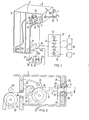
- FIG. 1 shows a highly simplified illustration of a dental device with a turbine handpiece 1 and an electric motor handpiece 2.
- the handpieces 1, 2 are held in storage sleeves 3.
- the media required for operating the two handpieces 1 and 2 air and water in the case of the turbine handpiece and electrical current and, if appropriate, air and water in the case of the electric motor handpiece
- a large part of the supply line 4 is received by a receiving shaft 6 located in the rear part of the device housing 5 when the handpiece is placed in the device.
- a holding and return device designated 8 which in principle is shown in more detail in FIG. 2 together with the hose guide.
- the media air, water and electrical current are supplied from supply sources 9, 10 and 11 to a supply module 12 (connection box) which contains solenoid valves 13, 14 for the media air and water and a relay 15 for the connection of electrical current.
- the media are - of course separated - fed via a line section 16 to a distribution box 17 arranged in the device housing 5 and from there via a line section 16a fed to a foot switch 18, which in turn contains two release valves 19, 20 and one or more electrical switches 21.
- the foot switch 18 is designed in a known manner so that the electrical switching means 21 and / or the release valves 19, 20 for supplying the media to the handpieces 1 or 2 are switched by an actuating lever 22 designed as a pivoting or depressing lever.
- the media are then fed via a line section 16b. fed into the corresponding supply line 4 for the handpiece 2 (or via the supply line for the handpiece 1, not shown).
- the holding and retraction device 8 for the supply line 4 contains an electric motor 23, on the drive axis of which a transport roller 24 is placed. With 25 a spring-loaded pressure roller is designated, which presses the supply line 4 for a uniform transport with a sufficient contact pressure on the transport roller 24.
- FIG. 2 shows the arrangement of the holding and return device as well as the hose lead-through enlarged in principle on the basis of a sectional illustration.
- an acceleration sensor 26 consisting of a hose lead-through part 27, two piezo plates 28 attached to it and two counter-bearings 29.
- the piezo plates 28 are on the one hand between the hose lead-through part 27 and on the other hand between the counter bearings 29 attached to the housing 5 are clamped in such a way that pressure or tensile loads which act on the hose guide part 27 are transmitted to the piezo plates.
- the piezo plates can also be fastened at another suitable location in the housing, for example below the cover side of the housing part 5.
- the transport roller 24 driven by the motor 23 is assigned a light barrier 30 (fork or reflection light barrier) which detects the movement of the roller in one direction or the other.
- a further light barrier also fork or reflection light barrier
- This light barrier serves to detect the direction of movement of the supply line 4, i.e. to report whether the hose is extended or retracted.
- the light barrier 30 In order to avoid any possible slippage between the hose and the motor-driven transport roller 24, it is conceivable for the light barrier 30 to cooperate with a control disk 33 at a point separate from the transport roller 24 (see dashed line). Of course, a pressure roller 25 ′ resting against the hose 4 is then also to be provided.
- the waves thus created exert compressive or tensile stresses on the piezo plates 28 via the parts 27 which are proportional to the acceleration.
- the voltages generated are converted into control signals with which the drive motor 23 for the holding and retraction device 8 is finally controlled.
- an inductive principle can also be used.
- a permanent magnet moved in a plunger coil may be attached to the hose nozzle or to the hose guide part 27. With a whip-like movement of the supply line, a voltage is generated in the coil, which in turn is the same as the acceleration movement of the supply line. The arrangement can also be reversed so that the permanent magnet is fixed and the moving coil is moved.
- a return device which can be brought into its starting position by weight can also be provided in a conventional manner.
- a deflection roller provided with latch catches (corresponding to the transport roller 24) can be provided, which interacts with an interlock that can be disengaged by an electric motor.
- the electric lifting magnet for unlocking the locking mechanism can, as explained above, be controlled by means of the acceleration sensors, which in turn can be of piezoelectric or inductive design.
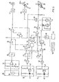
- the block diagram for the control of the servomotor 23 for the hose return and on the other hand of a drive motor 35 located in the handpiece 2 and for the preparatory switching on of the media via the supply module 12 are explained with reference to FIG.
- the piezo plates 28 of the accelerometer 26 are connected to a comparator 36, the switching threshold of which can be set by means of a potentiometer 37.
- the output of the comparator 36 leads to a retriggerable monostable multivibrator 38, at whose output Q an OR gate 39 is indicated is closed.
- the output of the OR gate 39 is connected to an AND stage 40, to whose output a matching circuit (interface circuit) 41 is connected, which controls the servomotor 23 for the line return.
- the command detector 30, which detects the movement of the supply line 4, contains an optotransistor 43 acted upon by a photodiode 42.
- the pulses which arise when the hose is moved are processed by a Schmitt trigger gate 44 in order to achieve the required falcon steepness for the subsequently retriggerable monostable Get flip level 45.
- This command detector also contains an optotransistor exposed to light by a photodiode 46, the pulses of which are processed by a Schmitt trigger gate 48.
- the Q output of flip-flop 45 leads on the one hand to an AND stage 49 and on the other hand to an inverting stage 50, the output of which is connected to a D flip-flop stage 51.
- the output of the Schmitt trigger stage 48 leads, on the one hand, to the inverting stage 50 and, on the other hand, to the AND gate 49 via a further inverting stage 52.
- a control line leads from the motion detector 30 to a counter 53, the output of which is connected to the clock input of a further D flip-flop 54.
- the output Q of the D flip-flop 54 leads to an AND stage 55, while the other output, on the one hand, to the D flip-flop 51 and, on the other hand, to a matching circuit 56 connected is.
- the supply module denoted by 12 in FIG. 1 can be controlled via the matching circuit 56, as a result of which "preparation" for the switching on of the supply media air, water and electrical current takes place.
- 57 designates a delay circuit which is controlled via a further OR stage 58 and is used to control the matching circuit 60 via the AND stage 59 for switching on the drive motor 35 of the handpiece 2.
- the switching means 21 arranged in the foot switch 18 are connected to a negated AND gate 61, which, as will be explained in more detail below, prevents the servomotor 23 from starting when the pivot lever 22 of the foot switch 18 is actuated (handpiece item 2 in operation). and accelerometer 26 responds by inadvertent hose movement.
- the functioning of the circuit diagram is explained on the basis of the movement sequence of the supply line 4 when the handpiece 2 is removed.
- the two command detectors 30 and 31 are activated; the transport detector 31 detects that the instrument has been removed from the storage holder and the movement detector indicates that the hose is moving in the pull-out direction.
- the pulses from the motion detector 30 are fed to the counter 53, which sets a D-flip-flop after reaching a counter reading which can be defined as desired and which corresponds to a certain minimum hose extension length (useful> 20 cm).
- the reset inputs 62 and 63 of the counter 53 and D flip-flop 54 these are only in one direction of movement, namely in Be direction of movement out of the housing, activated. This is achieved via the gate 40, which only carries a low 1 signal when it moves "out of the housing".
- the reset inputs carry a 'high' signal.
- control device provides an electronic memory by means of the interface circuit 56 instead of the supply module 12 12a (shown in dashed lines in Figure 3), the example read the operating values of the instruments.
- the operating values read out from the memory 12a are transmitted via the interface circuit 60 to the pulled handpiece 2 or its drive.
- the direction of movement is stored in the D flip-flop 51 and logically linked via the OR gate 58.
- the foot-. switch 18 is not actuated.
- the voltage emitted by the piezo plate 28 is brought to the required voltage level by means of the comparator 36.
- the switching threshold i.e. the sensitivity of the piezo plate 28 can be adjusted via the potentiometer 37.
- the voltage pulse controls the retriggerable monostable multivibrator 38, which switches on the servomotor 23 for the return device via the gate logic 39, 40 and the matching circuit 41.
- the time constant of the flip-flop 38 must be chosen so large that motion and transport detectors 30 and 31 switch on and take over the further return conveyance.
- counter 53 and D flip-flop 54 are set to zero via their reset inputs 62 and 63. As a result, the possibly activated supply unit 12 is switched off.
- Information for the shutdown of the servomotor 23 is achieved by the gate logic. If the handpiece 2 is in the holder 3 or is also stopped outside (cf. position of the handpiece in FIG. 1), the pulses from the motion detector 30 are missing. As a result, the tilting stage 45 is no longer activated. The output Q of the multivibrator 45 blocks the servomotor 23 via the AND / OR link 49, 39 and 40.
Landscapes
- Health & Medical Sciences (AREA)
- Engineering & Computer Science (AREA)
- Water Supply & Treatment (AREA)
- Oral & Maxillofacial Surgery (AREA)
- Dentistry (AREA)
- Epidemiology (AREA)
- Life Sciences & Earth Sciences (AREA)
- Animal Behavior & Ethology (AREA)
- General Health & Medical Sciences (AREA)
- Public Health (AREA)
- Veterinary Medicine (AREA)
- Dental Tools And Instruments Or Auxiliary Dental Instruments (AREA)
Applications Claiming Priority (2)
| Application Number | Priority Date | Filing Date | Title |
|---|---|---|---|
| DE19803014893 DE3014893A1 (de) | 1980-04-17 | 1980-04-17 | Steuereinrichtung fuer ein zahnaerztliches geraet |
| DE3014893 | 1980-04-17 |
Publications (3)
| Publication Number | Publication Date |
|---|---|
| EP0038452A2 true EP0038452A2 (fr) | 1981-10-28 |
| EP0038452A3 EP0038452A3 (en) | 1982-03-31 |
| EP0038452B1 EP0038452B1 (fr) | 1985-07-24 |
Family
ID=6100348
Family Applications (1)
| Application Number | Title | Priority Date | Filing Date |
|---|---|---|---|
| EP81102506A Expired EP0038452B1 (fr) | 1980-04-17 | 1981-04-02 | Dispositif de commande pour appareil dentaire |
Country Status (3)
| Country | Link |
|---|---|
| EP (1) | EP0038452B1 (fr) |
| JP (1) | JPS6057338B2 (fr) |
| DE (1) | DE3014893A1 (fr) |
Cited By (2)
| Publication number | Priority date | Publication date | Assignee | Title |
|---|---|---|---|---|
| FR2665354A1 (fr) * | 1990-08-03 | 1992-02-07 | Quetin Sa | Dispositif de pilotage des instruments d'une unite dentaire. |
| US6188837B1 (en) * | 1999-02-03 | 2001-02-13 | China Pacific Trade Ltd. | Hand-held hair dryer with retractable cord and controller responsive to amount of cord carried on cord reel |
Families Citing this family (2)
| Publication number | Priority date | Publication date | Assignee | Title |
|---|---|---|---|---|
| AT394807B (de) * | 1990-03-07 | 1992-06-25 | Inter Dent Dentalwaren Serv U | Lenk- und antriebsvorrichtung zur bewegung von, insbesondere medizinischen, geraeten und einrichtungen |
| DE19945208A1 (de) * | 1999-09-22 | 2001-04-26 | Ute Adrian | Chirurgische Werkzeugstation |
Family Cites Families (8)
| Publication number | Priority date | Publication date | Assignee | Title |
|---|---|---|---|---|
| US3872593A (en) * | 1965-10-20 | 1975-03-25 | Dentsply Research Dev Corp | Dental console |
| DE2434094A1 (de) * | 1974-07-16 | 1976-01-29 | Alfred Wieser | Zahnaerztliches geraet |
| DE2615827A1 (de) * | 1976-04-10 | 1977-10-13 | Litton Industries Inc | Vorrichtung zur aufbewahrung und unterbringung der versorgungsleitung eines zahnaerztlichen handinstrumentes |
| DE2621760B2 (de) * | 1976-05-15 | 1979-12-13 | Medtronic Gmbh, 6390 Usingen | Vorrichtung zum Einziehen und Aufbewahren der Versorgungsleitung eines zahnärztlichen Gerätes |
| US4106198A (en) * | 1976-11-12 | 1978-08-15 | Pelton & Crane Company | Control arrangement for handpiece instrument |
| US4114273A (en) * | 1976-11-12 | 1978-09-19 | Pelton & Crane Company | Handpiece instrument console apparatus having improved mechanisms for extending and retracting operating flexible hose |
| DE2733916C3 (de) * | 1977-07-27 | 1989-04-27 | Kaltenbach & Voigt Gmbh & Co, 7950 Biberach | Zahnärztliches Gerät mit mehreren Instrumenten |
| DE2823858C2 (de) * | 1978-05-31 | 1985-12-19 | Siemens AG, 1000 Berlin und 8000 München | Ablagevorrichtung für zahnärztliche Handstücke |
-
1980
- 1980-04-17 DE DE19803014893 patent/DE3014893A1/de active Granted
-
1981
- 1981-04-02 EP EP81102506A patent/EP0038452B1/fr not_active Expired
- 1981-04-16 JP JP56057803A patent/JPS6057338B2/ja not_active Expired
Cited By (3)
| Publication number | Priority date | Publication date | Assignee | Title |
|---|---|---|---|---|
| FR2665354A1 (fr) * | 1990-08-03 | 1992-02-07 | Quetin Sa | Dispositif de pilotage des instruments d'une unite dentaire. |
| EP0474577A1 (fr) * | 1990-08-03 | 1992-03-11 | Quetin S.A. | Dispositif de pilotage des instruments d'une unité dentaire |
| US6188837B1 (en) * | 1999-02-03 | 2001-02-13 | China Pacific Trade Ltd. | Hand-held hair dryer with retractable cord and controller responsive to amount of cord carried on cord reel |
Also Published As
| Publication number | Publication date |
|---|---|
| EP0038452B1 (fr) | 1985-07-24 |
| EP0038452A3 (en) | 1982-03-31 |
| DE3014893A1 (de) | 1981-10-22 |
| DE3014893C2 (fr) | 1988-04-07 |
| JPS6057338B2 (ja) | 1985-12-14 |
| JPS5729347A (en) | 1982-02-17 |
Similar Documents
| Publication | Publication Date | Title |
|---|---|---|
| EP0303651B1 (fr) | Procede d'interruption de l'entrainement, en particulier en percussion et/ou en rotation, d'un outil a main | |
| DE2819168A1 (de) | Spritzpistole mit sicherheitssensor | |
| EP0474994A1 (fr) | Appareil de placement et de rétraction d'une source radioactive dans un applicateur | |
| AT519095A4 (de) | Beschickungsverfahren für eine Werkzeugmaschine | |
| EP0861650B1 (fr) | Dispositif pour détecter l'enlèvement d'une pièce à main connectée à une conduite d'alimentation de son support | |
| EP2436415B1 (fr) | Dispositif de sortie destiné à la sortie de liquides | |
| EP0564411A1 (fr) | Dispositif de sertissage de connecteurs sur des yeux de lignes dénudées et/ou pour dénuder des lignes électriques ou optiques | |
| EP1980671B1 (fr) | Engin de compactage du sol sous forme de plaque vibrante | |
| EP0038452A2 (fr) | Dispositif de commande pour appareil dentaire | |
| DE1800048A1 (de) | Schleifmaschine,insbesondere aber eine Vorrichtung zur Herbeifuehrung einer Rotationsflaeche waehrend des Schleifvorganges | |
| DE102022104546A1 (de) | Pipette mit verstellbarem Pipettiervolumen und Verriegelungssystem | |
| EP0930963B1 (fr) | Dispositif de securite situe sur des machines-outils travaillant le metal par formage | |
| WO2014029796A2 (fr) | Outil à main | |
| EP0593063B1 (fr) | Système de commande pour une machine automobile guidé à la main | |
| DE3208819C2 (fr) | ||
| DE1452211B2 (de) | Kontrollvorrichtung an einer metallstrangpresse | |
| DE2609081C3 (de) | Vorrichtung zum Sortieren von Gegenständen | |
| DE2832520C2 (de) | Vorrichtung zum Entfernen der Restanoden von Anodenstangen | |
| DE2555827C2 (fr) | ||
| DE3929668C2 (de) | Lichtbogen-Bolzenanschweißvorrichtung | |
| DE102005047191B4 (de) | Vorrichtung zum Bearbeiten eines Werkstückes, insbesondere Umformvorrichtung zum Umformen eines Niets, sowie Verfahren zum Betreiben einer solchen Vorrichtung | |
| DE1831184U (de) | Selbsttaetig arbeitende maschine. | |
| DE1700418U (de) | Umschaltvorrichtung fuer den transport der endlosen papierkarte als dessinkarte an verdol-maschinen. | |
| EP1171897A1 (fr) | Dispositif de commande d'une liaison en fonction de l'etat d'un dispositif a surveiller, en particulier commutateur de securite | |
| DE102024104450A1 (de) | Automatische zugkupplung sowie verfahren zum betreiben einer automatischen zugkupplung |
Legal Events
| Date | Code | Title | Description |
|---|---|---|---|
| PUAI | Public reference made under article 153(3) epc to a published international application that has entered the european phase |
Free format text: ORIGINAL CODE: 0009012 |
|
| AK | Designated contracting states |
Designated state(s): FR GB IT SE |
|
| 17P | Request for examination filed |
Effective date: 19811028 |
|
| PUAL | Search report despatched |
Free format text: ORIGINAL CODE: 0009013 |
|
| AK | Designated contracting states |
Designated state(s): FR GB IT SE |
|
| ITF | It: translation for a ep patent filed | ||
| GRAA | (expected) grant |
Free format text: ORIGINAL CODE: 0009210 |
|
| AK | Designated contracting states |
Designated state(s): FR GB IT SE |
|
| ET | Fr: translation filed | ||
| PLBE | No opposition filed within time limit |
Free format text: ORIGINAL CODE: 0009261 |
|
| STAA | Information on the status of an ep patent application or granted ep patent |
Free format text: STATUS: NO OPPOSITION FILED WITHIN TIME LIMIT |
|
| 26N | No opposition filed | ||
| PG25 | Lapsed in a contracting state [announced via postgrant information from national office to epo] |
Ref country code: SE Effective date: 19880403 |
|
| PG25 | Lapsed in a contracting state [announced via postgrant information from national office to epo] |
Ref country code: GB Free format text: LAPSE BECAUSE OF NON-PAYMENT OF DUE FEES Effective date: 19881118 |
|
| GBPC | Gb: european patent ceased through non-payment of renewal fee | ||
| PGFP | Annual fee paid to national office [announced via postgrant information from national office to epo] |
Ref country code: FR Payment date: 19890421 Year of fee payment: 9 |
|
| ITTA | It: last paid annual fee | ||
| PG25 | Lapsed in a contracting state [announced via postgrant information from national office to epo] |
Ref country code: FR Effective date: 19901228 |
|
| REG | Reference to a national code |
Ref country code: FR Ref legal event code: ST |
|
| EUG | Se: european patent has lapsed |
Ref document number: 81102506.3 Effective date: 19890725 |