EP0038469A1 - Jointure par brides pour assembler des plaques - Google Patents
Jointure par brides pour assembler des plaques Download PDFInfo
- Publication number
- EP0038469A1 EP0038469A1 EP81102619A EP81102619A EP0038469A1 EP 0038469 A1 EP0038469 A1 EP 0038469A1 EP 81102619 A EP81102619 A EP 81102619A EP 81102619 A EP81102619 A EP 81102619A EP 0038469 A1 EP0038469 A1 EP 0038469A1
- Authority
- EP
- European Patent Office
- Prior art keywords
- clamping
- plate
- rail
- plates
- edge
- Prior art date
- Legal status (The legal status is an assumption and is not a legal conclusion. Google has not performed a legal analysis and makes no representation as to the accuracy of the status listed.)
- Granted
Links
- 238000003801 milling Methods 0.000 description 4
- 229910000746 Structural steel Inorganic materials 0.000 description 1
- 238000005266 casting Methods 0.000 description 1
- 238000010276 construction Methods 0.000 description 1
- 239000002184 metal Substances 0.000 description 1
- 229910052751 metal Inorganic materials 0.000 description 1
Images

Classifications
-
- F—MECHANICAL ENGINEERING; LIGHTING; HEATING; WEAPONS; BLASTING
- F16—ENGINEERING ELEMENTS AND UNITS; GENERAL MEASURES FOR PRODUCING AND MAINTAINING EFFECTIVE FUNCTIONING OF MACHINES OR INSTALLATIONS; THERMAL INSULATION IN GENERAL
- F16B—DEVICES FOR FASTENING OR SECURING CONSTRUCTIONAL ELEMENTS OR MACHINE PARTS TOGETHER, e.g. NAILS, BOLTS, CIRCLIPS, CLAMPS, CLIPS OR WEDGES; JOINTS OR JOINTING
- F16B5/00—Joining sheets or plates, e.g. panels, to one another or to strips or bars parallel to them
- F16B5/02—Joining sheets or plates, e.g. panels, to one another or to strips or bars parallel to them by means of fastening members using screw-thread
-
- A—HUMAN NECESSITIES
- A47—FURNITURE; DOMESTIC ARTICLES OR APPLIANCES; COFFEE MILLS; SPICE MILLS; SUCTION CLEANERS IN GENERAL
- A47B—TABLES; DESKS; OFFICE FURNITURE; CABINETS; DRAWERS; GENERAL DETAILS OF FURNITURE
- A47B87/00—Sectional furniture, i.e. combinations of complete furniture units, e.g. assemblies of furniture units of the same kind such as linkable cabinets, tables, racks or shelf units
- A47B87/002—Combination of tables; Linking or assembling means therefor
-
- F—MECHANICAL ENGINEERING; LIGHTING; HEATING; WEAPONS; BLASTING
- F16—ENGINEERING ELEMENTS AND UNITS; GENERAL MEASURES FOR PRODUCING AND MAINTAINING EFFECTIVE FUNCTIONING OF MACHINES OR INSTALLATIONS; THERMAL INSULATION IN GENERAL
- F16B—DEVICES FOR FASTENING OR SECURING CONSTRUCTIONAL ELEMENTS OR MACHINE PARTS TOGETHER, e.g. NAILS, BOLTS, CIRCLIPS, CLAMPS, CLIPS OR WEDGES; JOINTS OR JOINTING
- F16B5/00—Joining sheets or plates, e.g. panels, to one another or to strips or bars parallel to them
- F16B5/0004—Joining sheets, plates or panels in abutting relationship
- F16B5/0056—Joining sheets, plates or panels in abutting relationship by moving the sheets, plates or panels or the interlocking key perpendicular to the main plane
- F16B5/0068—Joining sheets, plates or panels in abutting relationship by moving the sheets, plates or panels or the interlocking key perpendicular to the main plane and using I-shaped clamps with flanges moving towards each other
- F16B5/0072—Joining sheets, plates or panels in abutting relationship by moving the sheets, plates or panels or the interlocking key perpendicular to the main plane and using I-shaped clamps with flanges moving towards each other and using screw-thread
Definitions
- the present invention relates to a device for clamping plates etc., which lie with one edge side against one another in essentially the same plane.
- the present invention has for its object to provide a device provided for clamping plates edge to edge, which results in clamping forces both parallel to and transversely to the plane of the plates and thereby brings about particularly good stability.
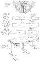
- FIG. 1 shows a part of a table top 1, 2, the edge surfaces 3, 4 of which only lie against one another with a part of their width, but otherwise by one along the entire edge surfaces 3, 4th running edge milling 5 or 6 are separated from each other.
- the inner part of the edge millings has a slot 7 or 8.
- An approximately U-shaped tensioning rail 9 extends along essentially the entire length of the edge surfaces 3, 4 and is provided with outwardly directed flanges 10, 11, FIG. 2, 3, each with a slot 7, 8.
- An essentially groove-shaped plate fitting 12, 13 is mounted against the underside 1 ', 2' of the table tops 1, 2 and on both sides of the tensioning rail 9 in parallel with the edge surfaces 3, 4 such that it matches the edge surface 14 'of one side 14, FIG. 4,5, against the underside 1 ', 2' of the table top in question and engages with its other side edge part 15 in a longitudinal groove 16 or 17 in the underside 1 ', 2' of each table top and with its edge surface 15 'preferably against the relevant one Table top bumps.
- the outer sides 18, 19 of the plate fittings 12, 13 form an angle of 90 ° with one another, and the sides 21, 22 of a trough-shaped stand rail 20, FIG.
- the described clamping device according to the invention offers the following advantages in particular.
- the clamping screws 23 are tightened, the stand rail 20 is pressed against the plate fittings 12, 13. Due to the aforementioned angle of 90 ° , the plate fittings 12, 13 drive the plates 1 , 2 tightly against one another and are supported by their edge surfaces 14 ', 15' against the underside of the plates 1 , 2.
- the plates are thereby given the same level position, and the plates are connected to one another in a particularly stable manner by the clamping forces acting parallel to and transversely to the plane of the plates 1, 2.
- edge millings 5, 6, slots 7, 8 and grooves 16, 17 required in a pair of plates on the edge surfaces, as well as the clamping rail 9 required in the clamping device, the plate fittings 12, 13 and the upright rail 20 including the clamping screws are all easy to machine and the plates can be easily connected or detached edge to edge by assembling or disassembling the present stapler.
- FIGS. 9 and 10 differs from that shown in FIGS. 1-8 essentially only in that the stand rail 26 is an angle iron forming an angle of 90 ° between its flanges (which is like the other parts in the clamp device , if preferred, consists of light metal) and extends along the entire connection.
- the plate fittings 27, 28 have a similar cross section as in FIG. 1, but, as shown in FIG. 10, are short in the longitudinal direction and fastened by means of screws 29.
- Each Plate 31, 32 has instead of the longitudinal slots 7, 8 and tensioning rail 9 in FIG. 1, shorter slots 33, 34 for a plate-shaped head 35 of the tensioning screw 36.
- This embodiment according to the invention also offers advantages similar to those for the device according to FIG. 1-8.
- the design with a screw head is simpler than a tensioning rail 9.
- the assembly of multiple plate fittings 28 means more work.
- FIG. 8 shows the clamp device in use for connecting table tops 1, 2, with each stand rail 20 being supported near one end by a leg 37 with a foot 38 parallel to the entire length of the stand rail.
- the stand rail can be carried in any arrangement.
- the edges of several different objects such as table tops, shelves, showcases in shops, department stores, showrooms and storage rooms, as well as multi-part molds for casting in house construction and the like. be releasably joined together.
- the invention is not only to be regarded as limited to the embodiments described and shown in the drawings, since these can be modified in particular in their partial training within the scope of the invention.
- the specified 90 ° angle e.g. can be changed depending on the mutual size ratio desired between the resulting clamping forces. If a plate-shaped screw head is used instead of a tensioning rail, the longitudinal edge millings in the abutting edge surfaces can be replaced by only one recess for the screw provided with the head.
Landscapes
- Engineering & Computer Science (AREA)
- General Engineering & Computer Science (AREA)
- Mechanical Engineering (AREA)
- Connection Of Plates (AREA)
- Clamps And Clips (AREA)
- Workshop Equipment, Work Benches, Supports, Or Storage Means (AREA)
- Meat, Egg Or Seafood Products (AREA)
Applications Claiming Priority (2)
| Application Number | Priority Date | Filing Date | Title |
|---|---|---|---|
| SE8002737 | 1980-04-11 | ||
| SE8002737A SE417236B (sv) | 1980-04-11 | 1980-04-11 | Klammeranordning for hopskarvning av skivor |
Publications (2)
| Publication Number | Publication Date |
|---|---|
| EP0038469A1 true EP0038469A1 (fr) | 1981-10-28 |
| EP0038469B1 EP0038469B1 (fr) | 1984-11-14 |
Family
ID=20340722
Family Applications (1)
| Application Number | Title | Priority Date | Filing Date |
|---|---|---|---|
| EP81102619A Expired EP0038469B1 (fr) | 1980-04-11 | 1981-04-07 | Jointure par brides pour assembler des plaques |
Country Status (9)
| Country | Link |
|---|---|
| EP (1) | EP0038469B1 (fr) |
| JP (1) | JPS56157979A (fr) |
| AU (1) | AU548235B2 (fr) |
| DE (1) | DE3167147D1 (fr) |
| DK (1) | DK148986C (fr) |
| FI (1) | FI69344C (fr) |
| NO (1) | NO151480C (fr) |
| SE (1) | SE417236B (fr) |
| SU (1) | SU1178333A3 (fr) |
Cited By (5)
| Publication number | Priority date | Publication date | Assignee | Title |
|---|---|---|---|---|
| GB2210131A (en) * | 1987-09-21 | 1989-06-01 | Beleggingsmaatschappij Bouwmat | Apparatus for interconnecting encased panels |
| FR2801943A1 (fr) * | 1999-12-03 | 2001-06-08 | Didier Faure | Dispositif d'assemblage sans vis apparente pour des lames de bois |
| WO2005095805A1 (fr) * | 2004-03-29 | 2005-10-13 | D P Bakewell Limited | Dispositifs pour joindre des elements |
| DE102013000598A1 (de) | 2013-01-16 | 2014-08-21 | Rudolf Harlos | Befestigungsschrauben |
| CN105437181A (zh) * | 2015-12-29 | 2016-03-30 | 常熟市徐润机电有限公司 | 一种高压工作台 |
Families Citing this family (2)
| Publication number | Priority date | Publication date | Assignee | Title |
|---|---|---|---|---|
| AU619366B2 (en) * | 1988-12-16 | 1992-01-23 | Paul H. Hartman | Radially expandable edge connector system |
| DE102014003827B4 (de) * | 2014-03-18 | 2018-02-01 | Theodor Rußler | Grat- und Ankerprofile |
Citations (4)
| Publication number | Priority date | Publication date | Assignee | Title |
|---|---|---|---|---|
| US3724886A (en) * | 1971-05-14 | 1973-04-03 | Svenska Flaektfabriken Ab | Joint between fireproof and pressuretight wall and ceiling elements |
| US3786611A (en) * | 1972-01-14 | 1974-01-22 | Ordeco Inc | Fastening system for joining structural members |
| NL7313621A (fr) * | 1972-10-06 | 1974-04-09 | ||
| FR2435662A1 (fr) * | 1978-09-08 | 1980-04-04 | Sarrau Sylviane | Elements de formes d'emboiture et d'imbrication par procede de glissements lateral |
Family Cites Families (1)
| Publication number | Priority date | Publication date | Assignee | Title |
|---|---|---|---|---|
| JPS49137312U (fr) * | 1973-03-24 | 1974-11-26 |
-
1980
- 1980-04-11 SE SE8002737A patent/SE417236B/sv not_active IP Right Cessation
-
1981
- 1981-03-26 FI FI810944A patent/FI69344C/fi not_active IP Right Cessation
- 1981-04-07 EP EP81102619A patent/EP0038469B1/fr not_active Expired
- 1981-04-07 DE DE8181102619T patent/DE3167147D1/de not_active Expired
- 1981-04-08 JP JP5376281A patent/JPS56157979A/ja active Granted
- 1981-04-10 NO NO811248A patent/NO151480C/no unknown
- 1981-04-10 DK DK163981A patent/DK148986C/da not_active IP Right Cessation
- 1981-04-10 SU SU813276846A patent/SU1178333A3/ru active
- 1981-10-26 AU AU76801/81A patent/AU548235B2/en not_active Ceased
Patent Citations (4)
| Publication number | Priority date | Publication date | Assignee | Title |
|---|---|---|---|---|
| US3724886A (en) * | 1971-05-14 | 1973-04-03 | Svenska Flaektfabriken Ab | Joint between fireproof and pressuretight wall and ceiling elements |
| US3786611A (en) * | 1972-01-14 | 1974-01-22 | Ordeco Inc | Fastening system for joining structural members |
| NL7313621A (fr) * | 1972-10-06 | 1974-04-09 | ||
| FR2435662A1 (fr) * | 1978-09-08 | 1980-04-04 | Sarrau Sylviane | Elements de formes d'emboiture et d'imbrication par procede de glissements lateral |
Cited By (7)
| Publication number | Priority date | Publication date | Assignee | Title |
|---|---|---|---|---|
| GB2210131A (en) * | 1987-09-21 | 1989-06-01 | Beleggingsmaatschappij Bouwmat | Apparatus for interconnecting encased panels |
| FR2801943A1 (fr) * | 1999-12-03 | 2001-06-08 | Didier Faure | Dispositif d'assemblage sans vis apparente pour des lames de bois |
| EP1106842A1 (fr) * | 1999-12-03 | 2001-06-13 | Didier Fauré | Dispositif d'assemblage sans vis apparente pour des lames de bois |
| US6470641B1 (en) | 1999-12-03 | 2002-10-29 | Didier Faure | Assembly device without visible screws for wooden slats |
| WO2005095805A1 (fr) * | 2004-03-29 | 2005-10-13 | D P Bakewell Limited | Dispositifs pour joindre des elements |
| DE102013000598A1 (de) | 2013-01-16 | 2014-08-21 | Rudolf Harlos | Befestigungsschrauben |
| CN105437181A (zh) * | 2015-12-29 | 2016-03-30 | 常熟市徐润机电有限公司 | 一种高压工作台 |
Also Published As
| Publication number | Publication date |
|---|---|
| FI810944L (fi) | 1981-10-12 |
| NO151480B (no) | 1985-01-02 |
| SU1178333A3 (ru) | 1985-09-07 |
| NO811248L (no) | 1981-10-12 |
| DE3167147D1 (en) | 1984-12-20 |
| EP0038469B1 (fr) | 1984-11-14 |
| AU7680181A (en) | 1983-05-05 |
| NO151480C (no) | 1985-04-17 |
| FI69344B (fi) | 1985-09-30 |
| DK148986C (da) | 1986-06-30 |
| JPH0138966B2 (fr) | 1989-08-17 |
| FI69344C (fi) | 1986-01-10 |
| SE417236B (sv) | 1981-03-02 |
| JPS56157979A (en) | 1981-12-05 |
| DK163981A (da) | 1981-10-12 |
| AU548235B2 (en) | 1985-12-05 |
| DK148986B (da) | 1985-12-09 |
Similar Documents
| Publication | Publication Date | Title |
|---|---|---|
| DE2437724A1 (de) | Verduebelungs-bohrlehre fuer zwei stirn-flachseitig miteinander zu verduebelnde werkstuecke | |
| EP0790792A1 (fr) | Table | |
| DE4217501A1 (de) | Mobiler medizinischer Gerätetisch | |
| EP0038469B1 (fr) | Jointure par brides pour assembler des plaques | |
| WO1993001418A1 (fr) | Dispositif pour la fixation invisible de panneaux a des structures porteuses | |
| DE2325148C3 (de) | Vorrichtung zum Zusammenbau von Profilen für Metallstrukturen | |
| DE4002691A1 (de) | Edv- und buerogeraetetraeger mit klemmbuegelbefestigung | |
| DE817191C (de) | Rahmenleiste | |
| DE102017130758A1 (de) | Untergestell für Möbel | |
| DE8912191U1 (de) | Vorrichtung zum Abgrenzen von Raumabschnitten | |
| EP1123021A2 (fr) | Systeme mobilier variable pour poste de travail, a montants verticaux et entretoises transversales horizontales | |
| DE2749477A1 (de) | Tragelement fuer ein regalbrett | |
| DE3701906A1 (de) | Podestbock zum aufbau von buehnen, tribuenen oder dgl., welcher mit betriebsmaessig loesbaren beinen versehen ist | |
| DE19615447A1 (de) | Wandsystem insbesondere für Messestände | |
| DE2101297A1 (de) | Labortisch | |
| EP0582104A2 (fr) | Aide à la vente | |
| DE3232091C1 (de) | Verbindung eines plattenfoermigen Moebelteils mit einer Traverse | |
| DE2944628A1 (de) | Verbindungsbeschlag | |
| DE29719761U1 (de) | Vorrichtung zum lösbaren Verbinden von Wandelementen | |
| DE2633602C3 (de) | Beschlag zur lösbaren Befestigung von Paneelwänden, Tragelementen für Kästen, Bodenträgern u.dgl. an Wänden | |
| DE2410211A1 (de) | Kombinationsmoebel | |
| DE20215530U1 (de) | Möbelbauelement | |
| DE3725224A1 (de) | Regalstaender | |
| DE2330007A1 (de) | Vorrichtung bei moebeln zum befestigen der beine an der zarge | |
| DE1400924A1 (de) | Anordnung zur loesbaren und einstellbaren Befestigung von Blechen |
Legal Events
| Date | Code | Title | Description |
|---|---|---|---|
| PUAI | Public reference made under article 153(3) epc to a published international application that has entered the european phase |
Free format text: ORIGINAL CODE: 0009012 |
|
| AK | Designated contracting states |
Designated state(s): CH DE FR GB NL |
|
| 17P | Request for examination filed |
Effective date: 19811015 |
|
| GRAA | (expected) grant |
Free format text: ORIGINAL CODE: 0009210 |
|
| AK | Designated contracting states |
Designated state(s): CH DE FR GB LI NL |
|
| REF | Corresponds to: |
Ref document number: 3167147 Country of ref document: DE Date of ref document: 19841220 |
|
| ET | Fr: translation filed | ||
| PLBE | No opposition filed within time limit |
Free format text: ORIGINAL CODE: 0009261 |
|
| STAA | Information on the status of an ep patent application or granted ep patent |
Free format text: STATUS: NO OPPOSITION FILED WITHIN TIME LIMIT |
|
| 26N | No opposition filed | ||
| PGFP | Annual fee paid to national office [announced via postgrant information from national office to epo] |
Ref country code: FR Payment date: 19930225 Year of fee payment: 13 |
|
| PGFP | Annual fee paid to national office [announced via postgrant information from national office to epo] |
Ref country code: GB Payment date: 19930226 Year of fee payment: 13 |
|
| PGFP | Annual fee paid to national office [announced via postgrant information from national office to epo] |
Ref country code: CH Payment date: 19930309 Year of fee payment: 13 |
|
| PGFP | Annual fee paid to national office [announced via postgrant information from national office to epo] |
Ref country code: DE Payment date: 19930427 Year of fee payment: 13 |
|
| PGFP | Annual fee paid to national office [announced via postgrant information from national office to epo] |
Ref country code: NL Payment date: 19930430 Year of fee payment: 13 |
|
| PG25 | Lapsed in a contracting state [announced via postgrant information from national office to epo] |
Ref country code: GB Effective date: 19940407 |
|
| PG25 | Lapsed in a contracting state [announced via postgrant information from national office to epo] |
Ref country code: LI Effective date: 19940430 Ref country code: CH Effective date: 19940430 |
|
| PG25 | Lapsed in a contracting state [announced via postgrant information from national office to epo] |
Ref country code: NL Effective date: 19941101 |
|
| GBPC | Gb: european patent ceased through non-payment of renewal fee |
Effective date: 19940407 |
|
| NLV4 | Nl: lapsed or anulled due to non-payment of the annual fee | ||
| PG25 | Lapsed in a contracting state [announced via postgrant information from national office to epo] |
Ref country code: FR Effective date: 19941229 |
|
| REG | Reference to a national code |
Ref country code: CH Ref legal event code: PL |
|
| PG25 | Lapsed in a contracting state [announced via postgrant information from national office to epo] |
Ref country code: DE Effective date: 19950103 |
|
| REG | Reference to a national code |
Ref country code: FR Ref legal event code: ST |