EP0038562A2 - Bahnschneidevorrichtung mit verstellbarer Messereinstellung - Google Patents
Bahnschneidevorrichtung mit verstellbarer Messereinstellung Download PDFInfo
- Publication number
- EP0038562A2 EP0038562A2 EP81103032A EP81103032A EP0038562A2 EP 0038562 A2 EP0038562 A2 EP 0038562A2 EP 81103032 A EP81103032 A EP 81103032A EP 81103032 A EP81103032 A EP 81103032A EP 0038562 A2 EP0038562 A2 EP 0038562A2
- Authority
- EP
- European Patent Office
- Prior art keywords
- axis
- housing
- frame
- drum
- journals
- Prior art date
- Legal status (The legal status is an assumption and is not a legal conclusion. Google has not performed a legal analysis and makes no representation as to the accuracy of the status listed.)
- Granted
Links
Images

Classifications
-
- B—PERFORMING OPERATIONS; TRANSPORTING
- B26—HAND CUTTING TOOLS; CUTTING; SEVERING
- B26D—CUTTING; DETAILS COMMON TO MACHINES FOR PERFORATING, PUNCHING, CUTTING-OUT, STAMPING-OUT OR SEVERING
- B26D7/00—Details of apparatus for cutting, cutting-out, stamping-out, punching, perforating, or severing by means other than cutting
- B26D7/26—Means for mounting or adjusting the cutting member; Means for adjusting the stroke of the cutting member
- B26D7/2628—Means for adjusting the position of the cutting member
- B26D7/265—Journals, bearings or supports for positioning rollers or cylinders relatively to each other
-
- A—HUMAN NECESSITIES
- A24—TOBACCO; CIGARS; CIGARETTES; SIMULATED SMOKING DEVICES; SMOKERS' REQUISITES
- A24C—MACHINES FOR MAKING CIGARS OR CIGARETTES
- A24C5/00—Making cigarettes; Making tipping materials for, or attaching filters or mouthpieces to, cigars or cigarettes
- A24C5/47—Attaching filters or mouthpieces to cigars or cigarettes, e.g. inserting filters into cigarettes or their mouthpieces
- A24C5/471—Attaching filters or mouthpieces to cigars or cigarettes, e.g. inserting filters into cigarettes or their mouthpieces by means of a connecting band
- A24C5/473—Cutting the connecting band
-
- B—PERFORMING OPERATIONS; TRANSPORTING
- B26—HAND CUTTING TOOLS; CUTTING; SEVERING
- B26D—CUTTING; DETAILS COMMON TO MACHINES FOR PERFORATING, PUNCHING, CUTTING-OUT, STAMPING-OUT OR SEVERING
- B26D5/00—Arrangements for operating and controlling machines or devices for cutting, cutting-out, stamping-out, punching, perforating, or severing by means other than cutting
- B26D5/02—Means for moving the cutting member into its operative position for cutting
-
- B—PERFORMING OPERATIONS; TRANSPORTING
- B26—HAND CUTTING TOOLS; CUTTING; SEVERING
- B26D—CUTTING; DETAILS COMMON TO MACHINES FOR PERFORATING, PUNCHING, CUTTING-OUT, STAMPING-OUT OR SEVERING
- B26D7/00—Details of apparatus for cutting, cutting-out, stamping-out, punching, perforating, or severing by means other than cutting
- B26D7/26—Means for mounting or adjusting the cutting member; Means for adjusting the stroke of the cutting member
- B26D7/2614—Means for mounting the cutting member
-
- B—PERFORMING OPERATIONS; TRANSPORTING
- B26—HAND CUTTING TOOLS; CUTTING; SEVERING
- B26D—CUTTING; DETAILS COMMON TO MACHINES FOR PERFORATING, PUNCHING, CUTTING-OUT, STAMPING-OUT OR SEVERING
- B26D7/00—Details of apparatus for cutting, cutting-out, stamping-out, punching, perforating, or severing by means other than cutting
- B26D7/26—Means for mounting or adjusting the cutting member; Means for adjusting the stroke of the cutting member
- B26D7/2628—Means for adjusting the position of the cutting member
-
- Y—GENERAL TAGGING OF NEW TECHNOLOGICAL DEVELOPMENTS; GENERAL TAGGING OF CROSS-SECTIONAL TECHNOLOGIES SPANNING OVER SEVERAL SECTIONS OF THE IPC; TECHNICAL SUBJECTS COVERED BY FORMER USPC CROSS-REFERENCE ART COLLECTIONS [XRACs] AND DIGESTS
- Y10—TECHNICAL SUBJECTS COVERED BY FORMER USPC
- Y10T—TECHNICAL SUBJECTS COVERED BY FORMER US CLASSIFICATION
- Y10T83/00—Cutting
- Y10T83/465—Cutting motion of tool has component in direction of moving work
- Y10T83/4766—Orbital motion of cutting blade
- Y10T83/4795—Rotary tool
- Y10T83/483—With cooperating rotary cutter or backup
- Y10T83/4833—Cooperating tool axes adjustable relative to each other
-
- Y—GENERAL TAGGING OF NEW TECHNOLOGICAL DEVELOPMENTS; GENERAL TAGGING OF CROSS-SECTIONAL TECHNOLOGIES SPANNING OVER SEVERAL SECTIONS OF THE IPC; TECHNICAL SUBJECTS COVERED BY FORMER USPC CROSS-REFERENCE ART COLLECTIONS [XRACs] AND DIGESTS
- Y10—TECHNICAL SUBJECTS COVERED BY FORMER USPC
- Y10T—TECHNICAL SUBJECTS COVERED BY FORMER US CLASSIFICATION
- Y10T83/00—Cutting
- Y10T83/465—Cutting motion of tool has component in direction of moving work
- Y10T83/4766—Orbital motion of cutting blade
- Y10T83/4795—Rotary tool
- Y10T83/483—With cooperating rotary cutter or backup
- Y10T83/4838—With anvil backup
Definitions
- the present invention relates to appparatus for sectioning a continuous web of material.
- Web sectioning apparatus is described in United States patent applications 941,497 filed September 11, 1978 and 967,782 filed December 8, 1978, both of which are assigned to the same assignee as the assignee of the present application and both of which are hereby incorporated by reference herein in their entirety.
- the apparatus described in such prior copending applications includes a drum and a rotary knife assembly which are mounted on parallel axes.
- the web to be sectioned is carried on the drum.
- the drum and the knife assembly are rotated so that the cutting edges of the knife assembly, which extend parallel to the axis of the knife assembly, will repetitively engage the drum and cut the web along lines transverse to its direction of elongation.
- Such apparatus is frequently used for sectioning cigarette tipping paper.
- each of the cutting edges of the knife assembly must precisely engage the surface of the drum. If the cutting edges engage the drum surface too forcefully, they will rapidly become dull; if the cutting edges do not touch the drum surface they will not cut the web cleanly.
- the knife assembly described in said copending application Serial Nos. 967, 782 provides means for precisely adjusting the position of each cutting edge relative to the axis of rotation of the knife assembly. ;
- the apparatus of the present invention includes a housing and a drum rotatably mounted to the housing.
- the housing has a pair of coaxial concave bearing surfaces. The common axis of such bearing surfaces is parallel to the axis of the drum.
- a frame having a pair of coaxial journals is provided. Each journal of the frame is received in an associated one of the aforementioned bearing surfaces.
- a knife assembly is rotatably mounted to; the frame between the journals on an axis of rotation which is parallel to the axis of the journals but which is eccentric therefrom.
- the knife assembly has at least one cutting edge which extends parallel to such axis of rotation.
- Clamp means are provided for selectively forcing each of the journals of the frame against the associated bearing surface to fix the frame to the housing.
- the clamp means can also be operated to release the journals from such engagement.
- Movement means are provided for controllably pivoting the frame on the bearing surfaces when the journals are so released.
- the degree of engagement between the cutting edge of the knife assembly and the surface of the drum may be adjusted by releasing the clamp means and operating the movement means to pivot the frame on the bearing surfaces. Because the axis of rotation of the knife assembly is eccentric from the axis of the journals, such pivoting action will move the axis of rotation of the knife assembly towards or away from the drum surface as desired. After the desired adjustment has been accomplished, the clamp means are operated to again force the journals against the associated bearing surfaces. The clamp means will thus prevent any further pivoting of the frame relative to the housing during operation of the apparatus. Also, because each journal is forced against its associated bearing surface during operation of the apparatus, there can be no undesired linear movement or "slop" at the junctures of the bearing surfaces and the journals during operation. Thus, the clamp means, together with the bearing surfaces and journals, provide what is effectively a slop-free, selectively pivotable joint between the frame and the housing.
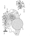
- apparatus includes a housing 10 and a cylindrical drum 12 rotatably mounted to the housing by means of a shaft 14 and bearings (not shown).
- a frame 16 is provided with a pair of cylindrical journals 18 and 20 (FIG. 1).
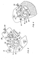
- the housing 10 is provided with a first concave, semi-cylindrical bearing surface 22, and the first journal 18 of the frame is received in the concavity of this surface.
- the frame is also provided with a second semi-cylindrical concave bearing surface 24, and the second journal 20 is received in the concavity of this surface.
- the bearing surfaces 22 and 24 are coaxial with one another, as are the journals 18 and 20 of the frame 16.
- the journals and the bearing surfaces serve to cooperatively mount the frame to the housing 10 for pivoting motion about an axis 26.
- the axis 26 is parallel to the axis of the drum 12.
- a clamp plate 28 is removably mounted to the housing 10 by a pair of screws 30.
- the plate 28 defines portions 32 and 34 of a further semi-cylindrical bearing surface.
- the surfaces 32, 34 and 22 provide a free running fit with the first journal 18 of the frame 16.
- a block 36 is slidably mounted to the clamp plate 28, and is thus slidably mounted to the housing 10.
- the lower end of the block 36 overlies the journal 18.
- a jack bolt 40 is threadedly engaged with the clamp plate 28; the lower end of the jack bolt 40 bears upon the upper end of the block 36.
- the block 36 may be forced toward the bearing surface 22 of the housing and toward the drum (downwardly and to the left as seen in FIG.
- a lock plate 42 is mounted to the block 36 by means of pins 44. Screws 46 extend through the lock plate 42 into the block 36. By tight- ening the screws 46, the lock plate can be pressed against the side wall of the clamp plate 28 to fix the position of the block 36 relative to the clamp plate 28 and thus relative to the housing 10 after the bolt 40 has been tightened.
- a second block 48 is slidably mounted to the housing adjacent to the second bearing surface 24.
- the second block 48 has a concave semi-cylindrical surface 50 which overlies the second journal 20.
- a second jack bolt 52 is threadedly engaged with the housing 10; by tightening this second jack bolt 52, the second block 48 may be forced toward the second bearing surface 24 and toward the drum (downwardly and to the left as seen in FIG. 4).
- a gib screw 54 is threadedly engaged with an extension of the block 48. By tightening the gib screw 54, the position of the block 48 relative to the housing 10 may be fixed.
- the blocks 36 and 48 are arranged to force the journals toward the bearing surfaces on a line of action which extends through the axis of the bearing surfaces and the axis of the drum.
- a knife assembly 56 is mounted to the frame 16 between the journals 18 and 20 by means of stub shafts 58 and 60 and anti-friction bearings 62 and 64.
- the axis of rotation 66 of the knife assembly with respect to the frame 16 is parallel to the axis 26 of the journals 18 and 20, the axis 66 is eccentric with respect to the axis 26.
- the axis of rotation 66 of the knife assembly with respect to the frame 16 lies beneath the axis 26 of the journals and bearing surfaces.
- the knife assembly 56 is provided with a plurality of cutting edges 68 which extend parallel to the axis of rotation 66 of the knife assembly 56.
- the knife assembly 56 is rotated counterclockwise and the drum 12, carrying a web of material (not shown) is rotated clockwise by an appropriate drive means 69 (FIG. 1).
- Such rotation causes the cutting edges of the knife assembly to engage the surface of the drum and part the web.
- the closer the axis 66 is to the axis of the drum the more heavily the cutting edges 68 will engage the surface of the drum.
- the knife assembly is of the type described in the aforementioned United States patent application 967, 782.
- a control element 70 is rotatably mounted to an upward extension 72 of the housing 10.
- a knob 74 is fixed to an extension of the control element 70 so that the control element may be manually rotated.
- a detent 76 is provided to prevent unintentional rotation of the control element 70.
- the control element 70 has internal helical threads 78 concentric with its axis of rotation.
- a link 80 having external helical threads 82 is threadedly engaged with the control element.
- the link 80 has a cylindrical cam surface 84 at its right hand end.
- a shackle 86 is pivotally mounted to the link on an axis concentric with the axis of cam surface 84.
- a shackle end plate 88 is fixed to the end of the shackle remote from the link.
- a set screw 90 is threadedly engaged with the shackle end plate 88.
- An arm 92 extends upwardly from the frame 16 between the shackle end plate 88 and the cam surface 84 of the link.
- the set screw 90 serves to maintain the front surface 94 of the arm in contact with the cam surface 84 of the link.
- the arm 92 extends transversely of the axis 26 of the bearing surfaces and journals.
- the link 80 By rotating'the control element 70, the link 80 (FIG. 2) may be controllably moved transversely of the arm 92.
- the degree of engagement of the cutting edges 68 with the drum 12 may be adjusted in the following manner: first, the clamp screws 46 (FIG. 3) and the gib screw 54 (FIG. 4) are loosened, and the jack bolts 52 and 40 are backed off to disengage the blocks 48 and 36 from the journals 18 and 20.
- the surface 32 and 34 of the clamp plate 28 will retain the frame 16 in pivotable but close engagement with the first bearing surface 22 even when the block 36 is disengaged from the journal 18.
- the second block 48 is preferably only slightly retracted from the journal 2 0 so that the journal 20 is also maintained in pivotable but close engagement with the second bearing surface 24.
- the control element 70 rotated by means of the knob 74 to move the link 80 to the right or to the left as seen in FIG. 2.
- Such movement of the link will cause the frame 16 to pivot about the axis 26 on the.bearing surfaces 24 and 22.
- the pivoting motion of the frame 16 on the axis 26 will move the axis of rotation 66 of the knife assembly towards or away from the drum.
- the link 80 is moved to the right as seen in FIG. 2
- the frame 16 will pivot clockwise and the axis of rotation 66 will be moved closer to the drum so that the cutting edges 68 will be more heavily engaged with the drum surface when the apparatus is later operated.
- movement of the link 80 to the left will have the opposite effect.
- the jack bolts 40 and 52 are tightened to force the blocks 36 and 48 (FIGS. 3 and 4) towards the drum.
- the first block 36 will engage the first journal 18 and force it tightly against the first bearing surface 22.
- the second block 48 (FIG. 4) will engage the second journal 20 and force it tightly against the second bearing surface 24.
- the lock screws 46 and the gib crew 54 are tightened to hold the blocks 36 and 48 in position and thus maintain the tight engagement of the journals with the bearing surfaces.
- the forceful engagement of the blocks with the journals and of the journals with the bearing surfaces prevents any pivotal or linear movement of the frame 16 with respect to the housing 10 during operation.
- the eccentricity or distance between the axis of rotation 66 and the axis 26 as seen in the drawings has been greatly exaggerated in the drawings for purposes of illustration. In actual practice, this distance is preferably only about 060 inches.
- the axis of rotation of the knife assembly would be moved at most about 120 inches towards or away from the drum surface by a 180° pivoting motion of the frame 16 relative to the housing 10.
- the small pivoting motion produced by incremental motion of the link 80 will produce an even smaller motion of the axis of rotation.
- the distance of the link from the axis 26, the pitch of the threads 82 and 78 on the link and the control element, and the eccentricity between the axes 26 and 66 are chosen so that one half revolution of the knob will correspond to about three ten thousandths of an inch movement of the axis of rotation 66.
- FIG. 5 Apparatus according to an alternate embodiment of the present invention is partially depicted in FIG. 5.
- the threaded housing of a ball plunger 96 is threadedly engaged with the shackle end 88.
- the ball plunger includes a compression spring 98 which bears on a ball 100.
- the ball 100 in turn bears on the rear surface 102 of the arm 92.
- the spring 98 will maintain the front surface 94 of the arm in contact with the cam surface 84 of the link 80 during adjustment of the apparatus.
- the apparatus depicted in FIG. 5 is identical with the apparatus shown in FIGS. 1-4.
Landscapes
- Life Sciences & Earth Sciences (AREA)
- Forests & Forestry (AREA)
- Engineering & Computer Science (AREA)
- Mechanical Engineering (AREA)
- Paper (AREA)
Applications Claiming Priority (2)
| Application Number | Priority Date | Filing Date | Title |
|---|---|---|---|
| US143812 | 1980-04-23 | ||
| US06/143,812 US4308776A (en) | 1980-04-23 | 1980-04-23 | Web sectioning apparatus with adjustable knife engagement |
Publications (3)
| Publication Number | Publication Date |
|---|---|
| EP0038562A2 true EP0038562A2 (de) | 1981-10-28 |
| EP0038562A3 EP0038562A3 (en) | 1983-06-01 |
| EP0038562B1 EP0038562B1 (de) | 1985-11-06 |
Family
ID=22505759
Family Applications (1)
| Application Number | Title | Priority Date | Filing Date |
|---|---|---|---|
| EP81103032A Expired EP0038562B1 (de) | 1980-04-23 | 1981-04-22 | Bahnschneidevorrichtung mit verstellbarer Messereinstellung |
Country Status (5)
| Country | Link |
|---|---|
| US (1) | US4308776A (de) |
| EP (1) | EP0038562B1 (de) |
| BR (1) | BR8102425A (de) |
| DE (1) | DE3172804D1 (de) |
| MY (1) | MY8700900A (de) |
Families Citing this family (7)
| Publication number | Priority date | Publication date | Assignee | Title |
|---|---|---|---|---|
| US5216962A (en) * | 1990-01-16 | 1993-06-08 | Fimi S.P.A. Fabbrica Impianti Macchine Industriali | Shear for shearing laminar elements |
| US5083488A (en) * | 1991-04-12 | 1992-01-28 | Melvin Stanley | Radially adjustable anvil roll assembly for a rotary die cutting press |
| US5445054A (en) * | 1993-09-21 | 1995-08-29 | R. J. Reynolds Tobacco Company | Sheet cutting apparatus and method |
| US5802941A (en) * | 1996-08-26 | 1998-09-08 | Akron Steel Fabricators Co., Inc. | Adjustable cutting roll assembly for severing pieces of material and method for adjusting same |
| US7001477B2 (en) * | 2003-12-02 | 2006-02-21 | Kimberly-Clark Worldwide, Inc. | Cutting method and apparatus having an affixed knife |
| ITTO20040117A1 (it) * | 2004-02-27 | 2004-05-27 | Tek Srl | Kit per il gonfiaggio e la riparazione di articoli gonfiabili, in particolare pneumatici |
| US10857690B2 (en) | 2018-09-11 | 2020-12-08 | The Procter & Gamble Company | Method and apparatus for adjusting and maintaining a position of a cutting surface of a perforating apparatus |
Family Cites Families (5)
| Publication number | Priority date | Publication date | Assignee | Title |
|---|---|---|---|---|
| US2711935A (en) * | 1951-03-20 | 1955-06-28 | Strachan & Henshaw Ltd | Means for adjusting the position of a shaft and for indicating the extent of said adjustment |
| DE1216085B (de) * | 1964-04-18 | 1966-05-05 | Richard Winkler | Vorrichtung zum Schneiden von Fenster-oeffnungen und/oder anderen Form- oder Trennschnitten an einzeln nacheinander zugefuehrten Zuschnitten oder laufenden Bahnen aus Papier od. dgl. |
| GB1050754A (de) * | 1964-09-01 | 1900-01-01 | ||
| US3720126A (en) * | 1970-12-11 | 1973-03-13 | Tension Envelope Corp | Die test stand |
| US4130042A (en) * | 1977-07-25 | 1978-12-19 | Avery International Corporation | Adjustable anvil roll for die-cutting labels |
-
1980
- 1980-04-23 US US06/143,812 patent/US4308776A/en not_active Expired - Lifetime
-
1981
- 1981-04-22 DE DE8181103032T patent/DE3172804D1/de not_active Expired
- 1981-04-22 EP EP81103032A patent/EP0038562B1/de not_active Expired
- 1981-04-22 BR BR8102425A patent/BR8102425A/pt not_active IP Right Cessation
-
1987
- 1987-12-30 MY MY900/87A patent/MY8700900A/xx unknown
Also Published As
| Publication number | Publication date |
|---|---|
| BR8102425A (pt) | 1981-12-29 |
| US4308776A (en) | 1982-01-05 |
| MY8700900A (en) | 1987-12-31 |
| DE3172804D1 (en) | 1985-12-12 |
| EP0038562A3 (en) | 1983-06-01 |
| EP0038562B1 (de) | 1985-11-06 |
Similar Documents
| Publication | Publication Date | Title |
|---|---|---|
| US4308776A (en) | Web sectioning apparatus with adjustable knife engagement | |
| CN1173410A (zh) | 带有高度或角度调节机构的锯片和电动机装载装置 | |
| US4159661A (en) | Rotary cutter | |
| US4257294A (en) | Apparatus for severing sheet material | |
| US3084582A (en) | Rotatable shearing blades for progressive transverse cutting | |
| US4355554A (en) | Web sectioning apparatus including an interference indicator | |
| US6631661B2 (en) | Bevel locking system for a sliding compound miter saw | |
| US4179804A (en) | Adjustable roller cable feeding and stripping tool | |
| US4790222A (en) | Apparatus for cutting various forms out of a picture frame mat or the like | |
| JPH07115466B2 (ja) | 軸受装置 | |
| US3563173A (en) | Liquid-handling mechanism | |
| JPH01170536A (ja) | ロールフィード装置 | |
| US3511123A (en) | Top mounting for rotary slitters | |
| US4419915A (en) | Envelope opener device | |
| CN220697003U (zh) | 一种可调距的碎纸机结构 | |
| US3063302A (en) | Quick adjustable screw means | |
| US1965734A (en) | Printing press roller socket | |
| US6202461B1 (en) | Tangential thread rolling head | |
| US6752052B2 (en) | Cutter assembly | |
| CN221872714U (zh) | 一种开炼机下刀片装置 | |
| US745531A (en) | Gage for paper-cutters, &c. | |
| CN114083613B (zh) | 一种方便调整的重型撕边刀架及其工作原理 | |
| CN224208159U (zh) | 一种破碎刀具及破碎机 | |
| CA2584761A1 (en) | Shave tool and tool holder | |
| JPH0325922Y2 (de) |
Legal Events
| Date | Code | Title | Description |
|---|---|---|---|
| PUAI | Public reference made under article 153(3) epc to a published international application that has entered the european phase |
Free format text: ORIGINAL CODE: 0009012 |
|
| AK | Designated contracting states |
Designated state(s): CH DE GB IT LI NL |
|
| PUAL | Search report despatched |
Free format text: ORIGINAL CODE: 0009013 |
|
| AK | Designated contracting states |
Designated state(s): CH DE GB IT LI NL |
|
| RAP1 | Party data changed (applicant data changed or rights of an application transferred) |
Owner name: PHILIP MORRIS INCORPORATED |
|
| 17P | Request for examination filed |
Effective date: 19830607 |
|
| GRAA | (expected) grant |
Free format text: ORIGINAL CODE: 0009210 |
|
| AK | Designated contracting states |
Designated state(s): CH DE GB IT LI NL |
|
| REF | Corresponds to: |
Ref document number: 3172804 Country of ref document: DE Date of ref document: 19851212 |
|
| ITF | It: translation for a ep patent filed | ||
| PLBE | No opposition filed within time limit |
Free format text: ORIGINAL CODE: 0009261 |
|
| STAA | Information on the status of an ep patent application or granted ep patent |
Free format text: STATUS: NO OPPOSITION FILED WITHIN TIME LIMIT |
|
| 26N | No opposition filed | ||
| REG | Reference to a national code |
Ref country code: CH Ref legal event code: PUE Owner name: PHILIP MORRIS PRODUCTS INC. |
|
| ITPR | It: changes in ownership of a european patent |
Owner name: CESSIONE;PHILIP MORRIS PRODUCTS INC. |
|
| NLS | Nl: assignments of ep-patents |
Owner name: PHILIP MORRIS PRODUCTS INC TE RICHMOND, VIRGINIE, |
|
| REG | Reference to a national code |
Ref country code: GB Ref legal event code: 732 |
|
| ITTA | It: last paid annual fee | ||
| PGFP | Annual fee paid to national office [announced via postgrant information from national office to epo] |
Ref country code: GB Payment date: 19940316 Year of fee payment: 14 |
|
| PGFP | Annual fee paid to national office [announced via postgrant information from national office to epo] |
Ref country code: CH Payment date: 19940325 Year of fee payment: 14 |
|
| PGFP | Annual fee paid to national office [announced via postgrant information from national office to epo] |
Ref country code: DE Payment date: 19940406 Year of fee payment: 14 |
|
| PGFP | Annual fee paid to national office [announced via postgrant information from national office to epo] |
Ref country code: NL Payment date: 19940430 Year of fee payment: 14 |
|
| PG25 | Lapsed in a contracting state [announced via postgrant information from national office to epo] |
Ref country code: GB Effective date: 19950422 |
|
| PG25 | Lapsed in a contracting state [announced via postgrant information from national office to epo] |
Ref country code: LI Effective date: 19950430 Ref country code: CH Effective date: 19950430 |
|
| PG25 | Lapsed in a contracting state [announced via postgrant information from national office to epo] |
Ref country code: NL Effective date: 19951101 |
|
| REG | Reference to a national code |
Ref country code: CH Ref legal event code: PL |
|
| GBPC | Gb: european patent ceased through non-payment of renewal fee |
Effective date: 19950422 |
|
| NLV4 | Nl: lapsed or anulled due to non-payment of the annual fee |
Effective date: 19951101 |
|
| PG25 | Lapsed in a contracting state [announced via postgrant information from national office to epo] |
Ref country code: DE Effective date: 19960103 |