EP0038579B1 - Belademechanismus für Müllfahrzeuge - Google Patents
Belademechanismus für Müllfahrzeuge Download PDFInfo
- Publication number
- EP0038579B1 EP0038579B1 EP19810200294 EP81200294A EP0038579B1 EP 0038579 B1 EP0038579 B1 EP 0038579B1 EP 19810200294 EP19810200294 EP 19810200294 EP 81200294 A EP81200294 A EP 81200294A EP 0038579 B1 EP0038579 B1 EP 0038579B1
- Authority
- EP
- European Patent Office
- Prior art keywords
- loading mechanism
- slide member
- rear opening
- driving means
- partition
- Prior art date
- Legal status (The legal status is an assumption and is not a legal conclusion. Google has not performed a legal analysis and makes no representation as to the accuracy of the status listed.)
- Expired
Links
- 230000007246 mechanism Effects 0.000 title claims description 32
- 238000005192 partition Methods 0.000 claims description 10
- 238000010276 construction Methods 0.000 description 3
- 239000000463 material Substances 0.000 description 3
- 229910000906 Bronze Inorganic materials 0.000 description 2
- 239000010974 bronze Substances 0.000 description 2
- KUNSUQLRTQLHQQ-UHFFFAOYSA-N copper tin Chemical compound [Cu].[Sn] KUNSUQLRTQLHQQ-UHFFFAOYSA-N 0.000 description 2
- 238000006073 displacement reaction Methods 0.000 description 2
- 238000000034 method Methods 0.000 description 2
- 230000008569 process Effects 0.000 description 2
- 230000008901 benefit Effects 0.000 description 1
- 230000008878 coupling Effects 0.000 description 1
- 238000010168 coupling process Methods 0.000 description 1
- 238000005859 coupling reaction Methods 0.000 description 1
- 230000007547 defect Effects 0.000 description 1
- 239000010791 domestic waste Substances 0.000 description 1
- 230000009467 reduction Effects 0.000 description 1
- 230000002787 reinforcement Effects 0.000 description 1
- 239000012791 sliding layer Substances 0.000 description 1
- 239000002699 waste material Substances 0.000 description 1
Images
Classifications
-
- B—PERFORMING OPERATIONS; TRANSPORTING
- B65—CONVEYING; PACKING; STORING; HANDLING THIN OR FILAMENTARY MATERIAL
- B65F—GATHERING OR REMOVAL OF DOMESTIC OR LIKE REFUSE
- B65F3/00—Vehicles particularly adapted for collecting refuse
- B65F3/14—Vehicles particularly adapted for collecting refuse with devices for charging, distributing or compressing refuse in the interior of the tank of a refuse vehicle
- B65F3/20—Vehicles particularly adapted for collecting refuse with devices for charging, distributing or compressing refuse in the interior of the tank of a refuse vehicle with charging pistons, plates, or the like
- B65F3/207—Vehicles particularly adapted for collecting refuse with devices for charging, distributing or compressing refuse in the interior of the tank of a refuse vehicle with charging pistons, plates, or the like guided by tracks, channels, slots or the like provided on the vehicle
Definitions
- the invention relates to a loading mechanism for a refuse vehicle whereby the rear opening extends substantially vertically between the floor and the sidewalls of the body of the refuse vehicle.
- a loading mechanism for a rearloading refuse vehicle e.g. for removing household waste.
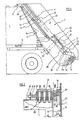
- the rear portion of a refuse vehicle shown in Figure 1 comprises the refuse body 1 with rear opening 2 at the top of which the loading mechanism 4 is pivotably fixed in hinge 3.
- the loading mechanism When the refuse vehicle 1 is being loaded, the loading mechanism rests with its sidewalls 5 against the rear opening 2 and with its underside or floor 6 against the extension plate 7 which at the bottom of the rear opening 2 is attached to the floor 8 of the refuse vehicle.
- the sidewalls 5 at both sides of the loading mechanism are connected to each other by a partition 9 which at its horizontal underedge joins a crossbeam 10.
- a hydraulic cylinder-piston pressure combination 11, 12 is mounted as driving means, which preferably extends parallel to the slide member 13.
- the upperend of the piston rod is connected to the upper end of the slide member.
- the slide member 13 is able to move up and down and in this process it is guided in suitable elongated slots 15 in both sidewalls 5 by means of the guiding means 16 described further on.
- the packer blade 17 is pivotably bearing-mounted in a known manner about rod 18. The rotation is also performed by a hydraulic cylinder 19 which has a support 20 in the framework of the slide member and whose piston rod 21 is hingedly attached to an extension piece 22 of the packer blade.
- the working cycle of the loading mechanism is as follows. We assume that the slide member is in its upper position and the packer blade is in open position 23 (dotted line). The refuse to be loaded is dumped into space 24 on floor 6 of the hopper and the slide member with opened packer blade 23 is slid downwards under the influence of the hydraulic pressure means 11, 12 until the packer blade reaches position 17.
- the cylinder 19 is now brought into operation and the plate 17 pivots around the rod 18 into its position 25. During this pivoting movement the plate 17 coacts with the floor 6 for compressing the dumped material and shoves it further on towards the rear opening 2.
- the cylinder 19 keeps its position and the slide member 13 is in coupling 14 again pushed upwards into its upper position 26 by pressure means 11-12.
- the packer blade so pushes the dumped material further upwards into the rear opening between the slide member wall 28 and the extension plate 7 towards its position 27.
- this loading mechanism permits the use of but one hydraulic pressure cylinder 11 or a similar driving means for the slide member. This simplifies the hydraulic pressure circuit, lowers the weight and the cost of the loading mechanism, as well as the risk of defect of the hydraulic circuit or the pressure cylinders.
- the position of cylinder 11 with fixed support 10 at the bottom also raises the pressure efficiency since the cylinder must exert most force exactly when it must push the slide member and the packer blade (traject from positions 25 to 27) carrying the material to be moved upwards.
- the entire piston surface 29 is used for this upward movement (without reduction of the piston rod cross section).
- these guiding means 16 preferably comprise friction blocks in combination with roller guides as sliding mechanisms as will be described further on with reference to the detailed drawing in Figure 2.
- FIG. 1 shows one of the upper corners of the slide member 13 as viewed from the rear side of the refuse vehicle and moving up and down along the inner side 31 of the sidewall 5 of the loading mechanism.
- the movement of the slide member in slot 15 is guided by guiding means 16 fixed to the upper edge 32 of the slide member.
- These guiding means 16 essentially comprise a bearing block 33 to whose end, extending in the slot 15, a rectangular friction block 34 is fixed and which comprises a sliding plate 35 e.g. made of bronze.
- the friction block 34-35 preferably slides against the walls 37 and 30 of the slot 15.
- a roller guide 36 is bearing mounted on this shaft end and normally rolls against the bottom transverse surface 30 of the slot 15.
- the bearing block 33 together with this guiding combination 34, 35, 36 is now preferably horizontally movable in the direction from and towards the sidewall 5.
- This offers the exceptional advantage that in case of frictional wear, particularly on the inner side 37 of the sidewall 5, the resulting play between the guiding means and wall 37 can be reduced. This is important since it is known by experience that increasing play in the slide member guiding slots leads to faster wear therein and on an average also requires more sliding energy. Moreover, chances increase that the guiding means 16 blocks in case of unequal loading on the packer blade across the width of the loading mechanism.
- the bearing block 33 is fixed to the upper side 32 of the slide member by means of bolt- nut connections 38 thereby using an intermediate clamping plate 39 and through suitable bores 40 in block 33.
- the bores have a elongated cross section with the greater transverse dimension in the direction perpendicular to the sidewall 5 so that a displacement of the bearing block in that direction becomes possible after that the bolts 38 have been slightly released.
- the displacement distance can be set by means of the nuts 41 against the stop 42 fixed to the upperside of the slide member.
- the invention is not limited to the embodiment of the loading mechanism herein described and illustrated.
- the partition 9 may be con- vexed (dotted line 43 in Figure 1) in the direction of the rear opening of the refuse body in order to stimulate the compressing process in the rear opening.
- the slot walls 30 and 37 may also be covered with a sliding layer.
- the roller 36 may also be replaced by a sliding block, for example made of bronze. Cylinder 11 can also be positioned not parallel with the slide member 13.
Landscapes
- Engineering & Computer Science (AREA)
- Mechanical Engineering (AREA)
- Refuse-Collection Vehicles (AREA)
Claims (5)
Applications Claiming Priority (2)
| Application Number | Priority Date | Filing Date | Title |
|---|---|---|---|
| BE1/9775A BE882651A (nl) | 1980-04-04 | 1980-04-04 | Laadinrichting voor stortgoedhouder |
| BE9775 | 1980-04-04 |
Publications (2)
| Publication Number | Publication Date |
|---|---|
| EP0038579A1 EP0038579A1 (de) | 1981-10-28 |
| EP0038579B1 true EP0038579B1 (de) | 1983-12-28 |
Family
ID=3862907
Family Applications (1)
| Application Number | Title | Priority Date | Filing Date |
|---|---|---|---|
| EP19810200294 Expired EP0038579B1 (de) | 1980-04-04 | 1981-03-16 | Belademechanismus für Müllfahrzeuge |
Country Status (3)
| Country | Link |
|---|---|
| EP (1) | EP0038579B1 (de) |
| BE (1) | BE882651A (de) |
| DE (1) | DE3161740D1 (de) |
Families Citing this family (3)
| Publication number | Priority date | Publication date | Assignee | Title |
|---|---|---|---|---|
| CN106742985A (zh) * | 2017-03-16 | 2017-05-31 | 龙岩鑫丰环卫设备有限公司 | 水平式双向垃圾压缩设备及摆臂垃圾车 |
| CN108438677B (zh) * | 2018-04-10 | 2024-01-30 | 扬州金威环保科技有限公司 | 一种后装压缩式垃圾车 |
| CN111942781B (zh) * | 2020-08-25 | 2023-07-14 | 杰维美亚机电设备(淮北)有限公司 | 一种用于垃圾运输车的垃圾箱固定机构 |
Family Cites Families (3)
| Publication number | Priority date | Publication date | Assignee | Title |
|---|---|---|---|---|
| US3615029A (en) * | 1969-03-21 | 1971-10-26 | Orin M Anderson | Rear loading refuse vehicle |
| DE2736572A1 (de) * | 1977-08-13 | 1979-02-22 | Haller Gmbh Fahrzeugbau | Hydraulisches betaetigungssystem, insbesondere fuer presschaufeln an muell- oder aehnlichen schuettgutbehaeltern |
| DE2742401C3 (de) * | 1977-09-21 | 1985-12-12 | Fahrzeugbau Haller Gmbh, 7000 Stuttgart | Beladevorrichtung für Schüttgutbehälter |
-
1980
- 1980-04-04 BE BE1/9775A patent/BE882651A/nl not_active IP Right Cessation
-
1981
- 1981-03-16 DE DE8181200294T patent/DE3161740D1/de not_active Expired
- 1981-03-16 EP EP19810200294 patent/EP0038579B1/de not_active Expired
Also Published As
| Publication number | Publication date |
|---|---|
| EP0038579A1 (de) | 1981-10-28 |
| BE882651A (nl) | 1980-10-06 |
| DE3161740D1 (en) | 1984-02-02 |
Similar Documents
| Publication | Publication Date | Title |
|---|---|---|
| US6007291A (en) | Packer system for refuse collection vehicle | |
| US4896593A (en) | Vertical trash compactor | |
| US5427496A (en) | Apparatus for packing separated materials | |
| US5324161A (en) | Refuse receptacle charging hopper | |
| EP0637555B1 (de) | Müllsammelfahrzeug mit einem festen hinteren Einschüttgehäuse und einer Vorrichtung zum Heben und Entleeren von Müllbehältern | |
| GB2158769A (en) | Refuse compactor | |
| PL167189B1 (pl) | Prasa do odpadków, zwlaszcza smieci PL PL | |
| US4235165A (en) | Compactor for waste material | |
| EP0038579A1 (de) | Belademechanismus für Müllfahrzeuge | |
| US4120409A (en) | Hopper barge having a bottom discharge opening closable by hopper doors | |
| EP0514355B1 (de) | Müllfahrzeug mit einer Vorrichtung zum Beschicken, Verdichten und Entleeren des Mülls | |
| US3937139A (en) | Compressing refuse | |
| US3777917A (en) | Tailgate for a rear loader refuse vehicle | |
| EP2366639A1 (de) | Abfallverdichtungseinheit | |
| US3762321A (en) | Scrap crusher with loading means | |
| US6167803B1 (en) | Door assembly for waste-paper baler | |
| US4309141A (en) | Refuse-extruder-and-compactor apparatus | |
| US4129222A (en) | Device for emptying containers or similar | |
| US3899090A (en) | Packer plate guide for refuse collection vehicles | |
| US3874529A (en) | Refuse loading apparatus | |
| CN215399785U (zh) | 一种具有主压头导向机构自动平衡的金属回收立式打包机 | |
| EP0096014A2 (de) | Müllsammelfahrzeug | |
| US3584433A (en) | Automated baling press with bale kick-out carton holding means and sequencing controls | |
| HUH3824A (en) | Apparatus for annihilating old windows | |
| US4104979A (en) | Hopper barge having a bottom discharge opening closed by hopper doors |
Legal Events
| Date | Code | Title | Description |
|---|---|---|---|
| PUAI | Public reference made under article 153(3) epc to a published international application that has entered the european phase |
Free format text: ORIGINAL CODE: 0009012 |
|
| AK | Designated contracting states |
Designated state(s): CH DE FR GB IT LU NL |
|
| 17P | Request for examination filed |
Effective date: 19820315 |
|
| ITF | It: translation for a ep patent filed | ||
| GRAA | (expected) grant |
Free format text: ORIGINAL CODE: 0009210 |
|
| AK | Designated contracting states |
Designated state(s): CH DE FR GB IT LI LU NL |
|
| PGFP | Annual fee paid to national office [announced via postgrant information from national office to epo] |
Ref country code: CH Payment date: 19840113 Year of fee payment: 4 |
|
| REF | Corresponds to: |
Ref document number: 3161740 Country of ref document: DE Date of ref document: 19840202 |
|
| PGFP | Annual fee paid to national office [announced via postgrant information from national office to epo] |
Ref country code: DE Payment date: 19840227 Year of fee payment: 4 |
|
| ET | Fr: translation filed | ||
| PG25 | Lapsed in a contracting state [announced via postgrant information from national office to epo] |
Ref country code: LU Free format text: LAPSE BECAUSE OF NON-PAYMENT OF DUE FEES Effective date: 19840331 |
|
| PLBE | No opposition filed within time limit |
Free format text: ORIGINAL CODE: 0009261 |
|
| STAA | Information on the status of an ep patent application or granted ep patent |
Free format text: STATUS: NO OPPOSITION FILED WITHIN TIME LIMIT |
|
| 26N | No opposition filed | ||
| REG | Reference to a national code |
Ref country code: CH Ref legal event code: PUE Owner name: MOL COMPANY N.V. |
|
| NLS | Nl: assignments of ep-patents |
Owner name: MOL COMPANY N.V. TE HOOGLEDE, BELGIE. |
|
| REG | Reference to a national code |
Ref country code: FR Ref legal event code: TP |
|
| ITPR | It: changes in ownership of a european patent |
Owner name: CESSIONE;MOL COMPANY N.V. |
|
| PGFP | Annual fee paid to national office [announced via postgrant information from national office to epo] |
Ref country code: NL Payment date: 19870331 Year of fee payment: 7 |
|
| REG | Reference to a national code |
Ref country code: GB Ref legal event code: 732 |
|
| PGFP | Annual fee paid to national office [announced via postgrant information from national office to epo] |
Ref country code: LU Payment date: 19890201 Year of fee payment: 9 |
|
| PG25 | Lapsed in a contracting state [announced via postgrant information from national office to epo] |
Ref country code: LI Effective date: 19890331 Ref country code: CH Effective date: 19890331 |
|
| PG25 | Lapsed in a contracting state [announced via postgrant information from national office to epo] |
Ref country code: NL Effective date: 19891001 |
|
| NLV4 | Nl: lapsed or anulled due to non-payment of the annual fee | ||
| REG | Reference to a national code |
Ref country code: CH Ref legal event code: PL |
|
| PG25 | Lapsed in a contracting state [announced via postgrant information from national office to epo] |
Ref country code: DE Effective date: 19891201 |
|
| ITTA | It: last paid annual fee | ||
| PGFP | Annual fee paid to national office [announced via postgrant information from national office to epo] |
Ref country code: GB Payment date: 19900331 Year of fee payment: 10 |
|
| PGFP | Annual fee paid to national office [announced via postgrant information from national office to epo] |
Ref country code: FR Payment date: 19900528 Year of fee payment: 11 |
|
| PG25 | Lapsed in a contracting state [announced via postgrant information from national office to epo] |
Ref country code: GB Effective date: 19910316 |
|
| GBPC | Gb: european patent ceased through non-payment of renewal fee | ||
| PG25 | Lapsed in a contracting state [announced via postgrant information from national office to epo] |
Ref country code: FR Effective date: 19911129 |
|
| REG | Reference to a national code |
Ref country code: FR Ref legal event code: ST |