EP0038631A2 - Vorrichtung und Verfahren zum Wägen und Mischen von Bitumen - Google Patents
Vorrichtung und Verfahren zum Wägen und Mischen von Bitumen Download PDFInfo
- Publication number
- EP0038631A2 EP0038631A2 EP81301330A EP81301330A EP0038631A2 EP 0038631 A2 EP0038631 A2 EP 0038631A2 EP 81301330 A EP81301330 A EP 81301330A EP 81301330 A EP81301330 A EP 81301330A EP 0038631 A2 EP0038631 A2 EP 0038631A2
- Authority
- EP
- European Patent Office
- Prior art keywords
- asphalt
- stabilizer
- mixer
- weigh
- surge
- Prior art date
- Legal status (The legal status is an assumption and is not a legal conclusion. Google has not performed a legal analysis and makes no representation as to the accuracy of the status listed.)
- Withdrawn
Links
Images


Classifications
-
- E—FIXED CONSTRUCTIONS
- E01—CONSTRUCTION OF ROADS, RAILWAYS, OR BRIDGES
- E01C—CONSTRUCTION OF, OR SURFACES FOR, ROADS, SPORTS GROUNDS, OR THE LIKE; MACHINES OR AUXILIARY TOOLS FOR CONSTRUCTION OR REPAIR
- E01C19/00—Machines, tools or auxiliary devices for preparing or distributing paving materials, for working the placed materials, or for forming, consolidating, or finishing the paving
- E01C19/02—Machines, tools or auxiliary devices for preparing or distributing paving materials, for working the placed materials, or for forming, consolidating, or finishing the paving for preparing the materials
- E01C19/10—Apparatus or plants for premixing or precoating aggregate or fillers with non-hydraulic binders, e.g. with bitumen, with resins, i.e. producing mixtures or coating aggregates otherwise than by penetrating or surface dressing; Apparatus for premixing non-hydraulic mixtures prior to placing or for reconditioning salvaged non-hydraulic compositions
- E01C19/1059—Controlling the operations; Devices solely for supplying or proportioning the ingredients
- E01C19/1063—Controlling the operations
-
- E—FIXED CONSTRUCTIONS
- E01—CONSTRUCTION OF ROADS, RAILWAYS, OR BRIDGES
- E01C—CONSTRUCTION OF, OR SURFACES FOR, ROADS, SPORTS GROUNDS, OR THE LIKE; MACHINES OR AUXILIARY TOOLS FOR CONSTRUCTION OR REPAIR
- E01C19/00—Machines, tools or auxiliary devices for preparing or distributing paving materials, for working the placed materials, or for forming, consolidating, or finishing the paving
- E01C19/02—Machines, tools or auxiliary devices for preparing or distributing paving materials, for working the placed materials, or for forming, consolidating, or finishing the paving for preparing the materials
- E01C19/10—Apparatus or plants for premixing or precoating aggregate or fillers with non-hydraulic binders, e.g. with bitumen, with resins, i.e. producing mixtures or coating aggregates otherwise than by penetrating or surface dressing; Apparatus for premixing non-hydraulic mixtures prior to placing or for reconditioning salvaged non-hydraulic compositions
- E01C19/1013—Plant characterised by the mode of operation or the construction of the mixing apparatus; Mixing apparatus
-
- E—FIXED CONSTRUCTIONS
- E01—CONSTRUCTION OF ROADS, RAILWAYS, OR BRIDGES
- E01C—CONSTRUCTION OF, OR SURFACES FOR, ROADS, SPORTS GROUNDS, OR THE LIKE; MACHINES OR AUXILIARY TOOLS FOR CONSTRUCTION OR REPAIR
- E01C19/00—Machines, tools or auxiliary devices for preparing or distributing paving materials, for working the placed materials, or for forming, consolidating, or finishing the paving
- E01C19/02—Machines, tools or auxiliary devices for preparing or distributing paving materials, for working the placed materials, or for forming, consolidating, or finishing the paving for preparing the materials
- E01C19/10—Apparatus or plants for premixing or precoating aggregate or fillers with non-hydraulic binders, e.g. with bitumen, with resins, i.e. producing mixtures or coating aggregates otherwise than by penetrating or surface dressing; Apparatus for premixing non-hydraulic mixtures prior to placing or for reconditioning salvaged non-hydraulic compositions
- E01C19/1059—Controlling the operations; Devices solely for supplying or proportioning the ingredients
- E01C19/1068—Supplying or proportioning the ingredients
Definitions
- the present method of mixing asphalt and stabilizer has been basically the same for a number of years.
- This method utilizes a mixing chamber having multiple rotating paddles into which asphalt and filler are introduced in measured amounts. After thorough mixing, the composition is discharged from a single opening into a processor holding vessel.
- the measuring of the asphalt and stabilizer as it is fed into the mixer is controlled by volume.
- the asphalt is heated and fed to the mixer by a positive displacement gear pump. This pump has a controllable speed so as to vary its output as well as measure volumetrically through the tooth spaces and revolutions per minute of the pump.
- the stabilizer is generally introduced either through a helicoid screw turning at a designated rpm and delivering stabilizer in measured volumetric amounts or the system-uses a rotary vane feeder that receives the filler in the voids between the vanes and measures it again volumetrically.
- Asphalt weight by volume varys depending on the temperature of the asphalt, therefore any variation in asphalt temperature varys the weight per cubic foot of the asphalt.
- the displacement pump which is used to deliver the asphalt, also has variables in the degree of accuracy or efficiency of the pump thus producing variables in measuring the amount fed to the mixer.
- the accuracy of the pump is also affected by the pressure at which the asphalt is brought up to the pump. Any variation in pressure can change the measurement of the asphalt as it passes through the pump.
- each stabilizer has a wide variation in weight by cubic measurement. Dolemite and limestone, depending on the grading and the region or country from which it is procured, can vary from 60 to 80 lbs. per cubic foot. Slate dust, oyster shells, available in the southern areas of the country, and fly ash are also used as stabilizers. Each of these also varies in weight, both with respect to each other and with respect to the other materials mentioned.
- the equipment used for volumetric measurement of the stabilizer also has inherent variables.
- the wear factor on a rotary helicoid screw is very great and as the wear occurs the amount of material delivered per revolution changes.
- Vane type feeders are less susceptible to wear but also have this variable.
- the feed-in from the hopper to either the helicoid served or to the vane feeder can vary. There is no way of knowing whether the amount of material delivered to the screw or vane is consistent with what the screw or vane will take away.
- the process and apparatus of the present invention provides a constant weight ratio of asphalt to stabilizer in the composition mix regardless of temperature or other environmental changes.
- the process is based on the use of weight as the criteria for controlling the ratio of the materials to be mixed.
- the process involves the simultaneously filling of separate containers with asphalt and stabilizer.
- the containers are weighed as they are being filled and the flow of asphalt or stabilizer stopped when a predetermined amount, by weight, has been delivered to each of the containers.
- the materials in the containers are then discharged into an interface mixer where the materials are mixed for a predetermined period of time prior to being fed to a surge tank or mixer.
- the asphalt and stabilizer composition is held in the surge tank or surge mixer until required for delivery to the process.
- the surge tank or mixer has the capacity to hold three or four times the amount of composition that is contained in the asphalt and stabilizer containers at one time. Thus, the surge tank or mixer can be discharged to process at a continuous rate of flow.
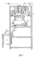
- the apparatus 5 generally includes a frame 10 for supporting a stabilizer weigh hopper or container 12, an asphalt weigh bucket or container 14, an intermediate mixer 16 and a surge mixer 18.
- the weigh hopper 12 is suspended from a beam scale 20.
- the weigh bucket 14 is suspended from a beam scale 22.
- Stabilizer from a source 26 and asphalt from a source 38 are fed by gravity feed or any other mechanical means to the weigh hopper 12 and bucket 14.
- the beam scales 20 and 22 record the weight of the stabilizer and asphalt as it is fed into the weigh hopper 12 and weigh bucket 14.
- Circuit means are provided for automatically stoppihg the flow of stabilizer and asphalt after a predetermined weight has been fed to the hopper 12 and bucket 14. After both the weigh hopper and bucket are filled, the stabilizer and asphalt are fed to the intermediate mixer 16.
- Stabilizer is fed from a source 26 to a hopper 28 by any convenient means and then transferred to the weigh hopper 12 by gravity or by means of a rotary vane feeder 30.
- the balance beam 32 is connected to the beam scale 20 by a line 33.
- the rotary vane feeder 30 is automatically shut off when a predetermined weight is registered on the beam scale 20.
- the balance beam 42 is connected to the beam scale 22 by a line 48.
- the valve 40 is opened to allow the asphalt to be pumped into the weigh bucket 14. When the beam scale 22 reaches the predetermined weight, the valve 40 is closed.
- the stabilizer in the weigh hopper 12 is fed to the intermediate mixer 16 by means of a screw conveyor 50 through an inlet pipe 52 connected to the intermediate mixer 16.
- the asphalt is fed through a valve 54 into an inlet tube 56 connected to the intermediate mixer 16.
- the asphalt and stabilizer flow by gravity simultaneously through the inlet tubes 52 and 56 into the intermediate mixer 16 where the asphalt and stabilizer are thoroughly mixed prior to delivery to the surge mixer 18.
- the intermediate mixer 16 By simultaneously feeding the asphalt and stabilizer into the intermediate mixer 16, it is premixed prior to delivery to the surge mixer 18.
- the intermediate mixer 16 is driven by means of a motor 58 and a belt 60.
- means are provided for controlling the time of mixing in the intermediate mixer. Such means is in the form of a timer 59.
- Means are provided for continuous mixing of the composition held in the surge mixer 18. Such means is in the form of a motor 64 provided on the mixer to drive a mixer assembly in the mixer 18.
- the stabilizer weigh hopper 12 and asphalt weigh bucket 14 are emptied, they are. immediately refilled preparatory to delivery to the" 'intermediate mixer 16. If the surge mixer 18 is not full when the intermediate mixer 16 is emptied, the weigh hopper 12 and weigh bucket 14 are immediately discharged to the intermediate mixer and fed to the surge mixer. As soon as the weigh hopper 12 and weight bucket 14 are emptied, they will again be refilled. If the surge mixer 18 has not been filled when the intermediate mixer 16 is emptied, the weigh hopper 12 and weigh bucket 14 will again be discharged into the intermediate mixer 16.
- This process is repeated until the surge mixer 18 is filled, at which time the weigh hopper 12 and weigh bucket 14 will be held until the level of the asphalt-stabilizer composition in the surge mixer is below a prescribed level.
- the surge mixer 18 will hold approximately four times the combined weight of the asphalt weigh bucket and stabilizer weigh'hopper so that a continuous flow of asphalt composition can be delivered for process from the surge mixer 18. If a continuous process is being carried on, continuous delivery of weighed amounts of asphalt and stabilizer will be delivered to the intermediate mixer to maintain a proper level of composition in the surge mixer.
- All of the containers and conduits used for the handling of the asphalt and stabilizer are therefore provided with jackets 62 to allow for the flow of high temperature fluid, such as oil or steam, through the jackets to maintain the temperature of the.asphalt and stabilizer.
- FIG. 4 a schematic diagram of the drive elements for the weigh system is shown. Switch locations for the various switches used to control the drive elements are also located in the figure.
- the filler hopper 28 includes high and low level switches M5 and M6 which indicate the level of filler in the hopper.
- a temperature control switch TC is also provided to maintain the proper temperature of the filler.
- the filler or stabilizer is fed by means of the rotary valve 30 which is controlled by a switch M3 into the filler weigh-hopper 12.
- the weight of the stabilizer in the hopper is sensed by switches S1/S2.
- the filler in the weigh hopper is fed to the horizontal mixer 16 by the screw conveyor.50 which is driven by a motor M4.
- the asphalt weigh bucket 14 is fed through a valve 40 controlled by a switch SV1.
- the asphalt in the bucket 14 is weighed by the scale 22 and sensed by switches S1/S2.
- Asphalt from the bucket is fed through a valve 54 controlled by a switch SV2 to the horizontal mixer 16.
- the horizontal mixer 16 is driven by a motor M2 and the mixed material is fed through a valve 61 controlled by a switch SV3 to the vertical mixer 18.
- the material in the vertical mixer is continuously mixed by a mixing member 64 driven by a motor Ml.
- the level of material in the vertical mixer is sensed by high and low level pressure switches HL and LL respectively and a holding switch OL is used to control the operation of the system whenever the material within the vertical mixer is below the high level or above the low level in the mixer.
- the electric circuit diagram for the system is shown in Figure 5.
- the motor circuit A for vertical mixer motor Ml, horizontal mixer motor M2, rotary feeder motor M3 and screw conveyor motor M4 are connected directly across the power lines and are controlled by motor control switches MC11, MC21, MC31, and MC41, respectively.
- the switches are controlled by a switch control circuit B connected to the secondary of a transformer Tl which is connected across the power lines.
- the sequence of operation of the motor control switches MC11, MC21, MC31, and MC41 is controlled by a number of corresponding motor control relays MC1, MC2, MC3, and MC4.
- control circuit B generally includes two manually operated switches SW1 and SW2.
- SW1 is closed to turn on the vertical mixer motor Ml by energizing relay MC1 and the horizontal motor mixer M2 by energizing the relay MC2.
- a number of overload switches O.L.'S are provided in each of the circuits for the relays MC1 and MC2.
- the vertical mixer Ml and horizontal mixer M2 run continuously until switch SW1 is opened.
- the weigh system is turned on by closing switch S W 2 to energize relay MC3 and switch SVl.
- Energizing switch SV1 opens valve 40 allowing asphalt to flow into bucket 14.
- Energizing relay MC3 closes the normally open relay switches MC31 for the-rotary feeder motor M3.
- the normally open filler scale weigh switch SFS1 When the stabilizer weigh hopper 12 is filled, the normally open filler scale weigh switch SFS1 will close energizing the control relay CR1.
- the normally open relay switches CR11, CR12 and CR13 will close and the normally closed relay switch CR14 will open. Opening the normally closed relay switch CR14 de-energizes relay MC3 stopping motor M3.
- Closing . switch CR12 sets up a holding circuit for relay CR1. Closing switch CR11 and CR13 establishes a preliminary condition for energizing relay CR5, relay MC4 and switch SV2 for dump valve 54.
- the control relay CR2 When the asphalt scale weigh switch SCS1 closes, the control relay CR2 will be energized opening normally closed switch CR21 to the switch SV1 closing the valve 40 and closing the normally opened control switches CR22 and CR23.
- the closed switch CR22 sets up a holding circuit to the relay CR2 and the closed switch CR23 completes the circuit to the motor control relay MC4 and switch SV2.
- Closing both of the normally open relay switches CR13 and CR23 initiates the flow of both stabilizer and asphalt to the horizontal mixer 16 by completing the circuit to the motor control relay MC4 and the asphalt discharge valve SV2.
- the filler scale zero switch SFS2 When the weight of the stabilizer and asphalt reaches zero, the filler scale zero switch SFS2 will close and the asphalt scale zero switch SCS2 will close energizing the scales' empty relay CR3.
- the two normally closed relay switches CR31 and CR32 will open and the normally open relay switch CR33 will close. Opening switch CR31 de-energizes relay CR3. Opening switch CR32 de-energizes relay CR2. Closing switch CR33 energizes the mix and dump relay CR5.
- De-energizing of the control relay CR1 recloses the normally closed control relay switch CRl4 to the relay MC3 which starts motor M3 to refill the stabilizer hopper 12.
- Energizing of the control relay CR2 recloses the normally closed relay switch CR21 re-energizing the switch SV1 to open the valve 40 to refill the asphalt weigh bucket.
- the switches SFS1 and SCS1 will both reclose as in the previous operation.
- Energizing relay CR5 closes normally open relay switches CR51 and CR52 and opens normally closed relay switch CR53. Closing switch CR51 sets up a holding circuit to relay CR5 and closing switch CR52 energizes the mixing time relay MT. Opening switch CR53 de-energizes relay MC4 stopping the screw conveyor 50 and switch SV2 closing valve 54.
- the mixer timer MT is also energized because the normally open switch CR5 is closed. After a preset time the normally opened switches in the mixing timer are closed to energize the delay timer DT. If the normally closed contacts of the high limit switch HL in the vertical mixer 18 is closed the mixer dump valve SV3 will open. When the delay timer DT completes its preset cycle, the normally closed contacts in the delay timer will open to de-energize the mixer dump valve SV3 and the the mix and dump relay CR5. If the operating level switch O.L. is open, the mix and dump valve relay CR5 will drop out allowing the full cycle to repeat.
Landscapes
- Engineering & Computer Science (AREA)
- Architecture (AREA)
- Civil Engineering (AREA)
- Structural Engineering (AREA)
- Road Paving Machines (AREA)
Applications Claiming Priority (2)
| Application Number | Priority Date | Filing Date | Title |
|---|---|---|---|
| US06/142,432 US4339202A (en) | 1980-04-21 | 1980-04-21 | Asphalt weigh and mix apparatus and process |
| US142432 | 1980-04-21 |
Publications (2)
| Publication Number | Publication Date |
|---|---|
| EP0038631A2 true EP0038631A2 (de) | 1981-10-28 |
| EP0038631A3 EP0038631A3 (de) | 1982-04-21 |
Family
ID=22499814
Family Applications (1)
| Application Number | Title | Priority Date | Filing Date |
|---|---|---|---|
| EP81301330A Withdrawn EP0038631A3 (de) | 1980-04-21 | 1981-03-27 | Vorrichtung und Verfahren zum Wägen und Mischen von Bitumen |
Country Status (2)
| Country | Link |
|---|---|
| US (1) | US4339202A (de) |
| EP (1) | EP0038631A3 (de) |
Cited By (3)
| Publication number | Priority date | Publication date | Assignee | Title |
|---|---|---|---|---|
| FR2568283A1 (fr) * | 1984-07-27 | 1986-01-31 | Beugnet Sa | Installation de fabrication et de stockage de melanges bitume-caoutchouc |
| CN109808068A (zh) * | 2019-02-25 | 2019-05-28 | 郑州三和水工机械有限公司 | 一种环保型混凝土搅拌楼 |
| CN111455779A (zh) * | 2020-04-20 | 2020-07-28 | 浙江威肯特智能机械有限公司 | 一种改性沥青的成套设备 |
Families Citing this family (12)
| Publication number | Priority date | Publication date | Assignee | Title |
|---|---|---|---|---|
| US4764019A (en) * | 1987-09-01 | 1988-08-16 | Hughes Tool Company | Method and apparatus for mixing dry particulate material with a liquid |
| US5149192A (en) * | 1988-09-30 | 1992-09-22 | Mixer Products, Inc. | System for mixing cementitious construction materials |
| US5203628A (en) * | 1988-09-30 | 1993-04-20 | Hamm Family Partnership | Portable batch mixing apparatus for cementitious construction materials |
| US5201472A (en) * | 1990-10-01 | 1993-04-13 | Astec Industries, Inc. | Method for preparing and storing a recyclable shingle material |
| DE19911060C2 (de) * | 1999-03-12 | 2001-04-26 | Mathis Technik | Verfahren zum kontinuierlichen Anmachen einer Baustoffmischung |
| GB2356824A (en) * | 2000-07-04 | 2001-06-06 | Allchem Internat Ltd | Apparatus for blending and delivering pelletised additives for incorporation in asphalt |
| US20100000442A1 (en) * | 2008-07-02 | 2010-01-07 | YK Holdings LLC | Apparatus for producing cold asphalt, method of manufacturing cold asphalt, and product-by-process for same |
| US20100027371A1 (en) * | 2008-07-30 | 2010-02-04 | Bruce Lucas | Closed Blending System |
| TR201102838A2 (tr) * | 2011-04-28 | 2011-08-22 | E-Mak Maki̇na İnşaat Ti̇caret Ve San. Ltd. Şti̇. | Geri kazanılmak istenen asfalttan yeni bir asfalt tabakası üretmek üzere sıcak asfalt hazırlama sistemi ve metodu |
| CN105133465A (zh) * | 2015-09-17 | 2015-12-09 | 江苏华通动力重工有限公司(中外合资) | 多功能厂拌设备 |
| US10358296B2 (en) * | 2015-09-18 | 2019-07-23 | Maxwell Properties, Llc | Systems and methods for delivering asphalt concrete |
| JP7687928B2 (ja) * | 2021-10-05 | 2025-06-03 | 日工株式会社 | アスファルトプラント |
Family Cites Families (10)
| Publication number | Priority date | Publication date | Assignee | Title |
|---|---|---|---|---|
| US808599A (en) * | 1905-03-01 | 1905-12-26 | George W Crichfield | Apparatus for mixing paving compositions. |
| CH199128A (de) * | 1937-10-02 | 1938-08-15 | Moll Hermann Ing Dipl | Verfahren und Vorrichtung zur Herstellung von bituminösem Mischgut für Strassenbeläge. |
| GB790898A (en) * | 1956-01-11 | 1958-02-19 | Barber Greene Co | Improvements in or relating to bituminous batch plants |
| US3058622A (en) * | 1958-01-14 | 1962-10-16 | Ballestra Mario | Device for continuously measuring, mixing and de-aerating materials fed to process plant |
| US3041049A (en) * | 1958-11-15 | 1962-06-26 | Tarukawa Tomiji | Mixing apparatus |
| CH497959A (de) * | 1968-08-21 | 1970-10-31 | Lico Ag | Mischmaschine, insbesondere für Beton |
| DE2008849A1 (de) * | 1970-02-25 | 1971-09-09 | Deutsche Asphalt GmbH, 6000 Frank fürt | Verfahren und Vorrichtung zum Mischen von Asphalt und dessen Verladung auf Transportfahrzeuge |
| US3697054A (en) * | 1970-12-10 | 1972-10-10 | Frank G Moratschek | Machine for making batches of mortar |
| US3866887A (en) * | 1973-12-13 | 1975-02-18 | Oolitic Ground Limestone Co In | Vertically integrated asphalt plant |
| FR2327048A1 (fr) * | 1975-10-08 | 1977-05-06 | Creusot Loire | Dispositif pour la preparation de produits principalement utilises pour la construction et l'entretien des routes |
-
1980
- 1980-04-21 US US06/142,432 patent/US4339202A/en not_active Expired - Lifetime
-
1981
- 1981-03-27 EP EP81301330A patent/EP0038631A3/de not_active Withdrawn
Cited By (3)
| Publication number | Priority date | Publication date | Assignee | Title |
|---|---|---|---|---|
| FR2568283A1 (fr) * | 1984-07-27 | 1986-01-31 | Beugnet Sa | Installation de fabrication et de stockage de melanges bitume-caoutchouc |
| CN109808068A (zh) * | 2019-02-25 | 2019-05-28 | 郑州三和水工机械有限公司 | 一种环保型混凝土搅拌楼 |
| CN111455779A (zh) * | 2020-04-20 | 2020-07-28 | 浙江威肯特智能机械有限公司 | 一种改性沥青的成套设备 |
Also Published As
| Publication number | Publication date |
|---|---|
| US4339202A (en) | 1982-07-13 |
| EP0038631A3 (de) | 1982-04-21 |
Similar Documents
| Publication | Publication Date | Title |
|---|---|---|
| US4339202A (en) | Asphalt weigh and mix apparatus and process | |
| US5110521A (en) | Hybrid apparatus and method for blending materials | |
| US4733971A (en) | Programmable weight sensitive microingredient feed additive delivery system and method | |
| EP2201341B1 (de) | Vorrichtung zur abmessung und mischung von komponenten aus giessbarem material | |
| US5219224A (en) | Programmable apparatus and method for delivering microingredient feed additives to animals by weight | |
| US5340211A (en) | Programmable apparatus and method for delivering microingredient feed additives by weight | |
| US4815042A (en) | Programmable apparatus and method for delivering microingredient feed additives to animals by weight | |
| KR0143227B1 (ko) | 유동물질의 정량측정 장치 및 그 측정방법과 그 방법의 응용 | |
| CN209530774U (zh) | 一种粉料制备过程自动配料装置 | |
| US2858594A (en) | Mixing plant | |
| EP0032460B1 (de) | Vorrichtung zum Wiegen und Mischen flüssiger und pulverförmiger Stoffe | |
| EP0062008B1 (de) | Betonmischanlagen mit Aufzugrad | |
| JPS61284615A (ja) | 流動性の生成物を重量により配量する装置 | |
| CN210453255U (zh) | 智能自动化制浆站 | |
| US4865457A (en) | Concrete batcher with segmented entry of mixing ingredients | |
| US2212419A (en) | Apparatus for batch weighing | |
| US2594975A (en) | Mixing apparatus | |
| CN104857888A (zh) | 一种自动配料系统 | |
| US3425501A (en) | Mixture proportioning apparatus | |
| US2288099A (en) | Continuous metering conveyer for bulk material | |
| EP0155062A1 (de) | Vorrichtung zur Vorbereitung einer Mischung | |
| IE60685B1 (en) | A method and apparatus for producing animal feed | |
| CN216037483U (zh) | 一种自动配料装置 | |
| US3164217A (en) | Weighing device | |
| US3129779A (en) | Weighing and discharge apparatus |
Legal Events
| Date | Code | Title | Description |
|---|---|---|---|
| PUAI | Public reference made under article 153(3) epc to a published international application that has entered the european phase |
Free format text: ORIGINAL CODE: 0009012 |
|
| AK | Designated contracting states |
Designated state(s): AT DE FR GB IT SE |
|
| 17P | Request for examination filed |
Effective date: 19811021 |
|
| PUAL | Search report despatched |
Free format text: ORIGINAL CODE: 0009013 |
|
| AK | Designated contracting states |
Designated state(s): AT DE FR GB IT SE |
|
| STAA | Information on the status of an ep patent application or granted ep patent |
Free format text: STATUS: THE APPLICATION IS DEEMED TO BE WITHDRAWN |
|
| 18D | Application deemed to be withdrawn |
Effective date: 19841109 |
|
| RIN1 | Information on inventor provided before grant (corrected) |
Inventor name: HART, WALLACE L. Inventor name: RICKETTS, JOHN W. |